-
1Getting Your PCB Manufactured
![]()
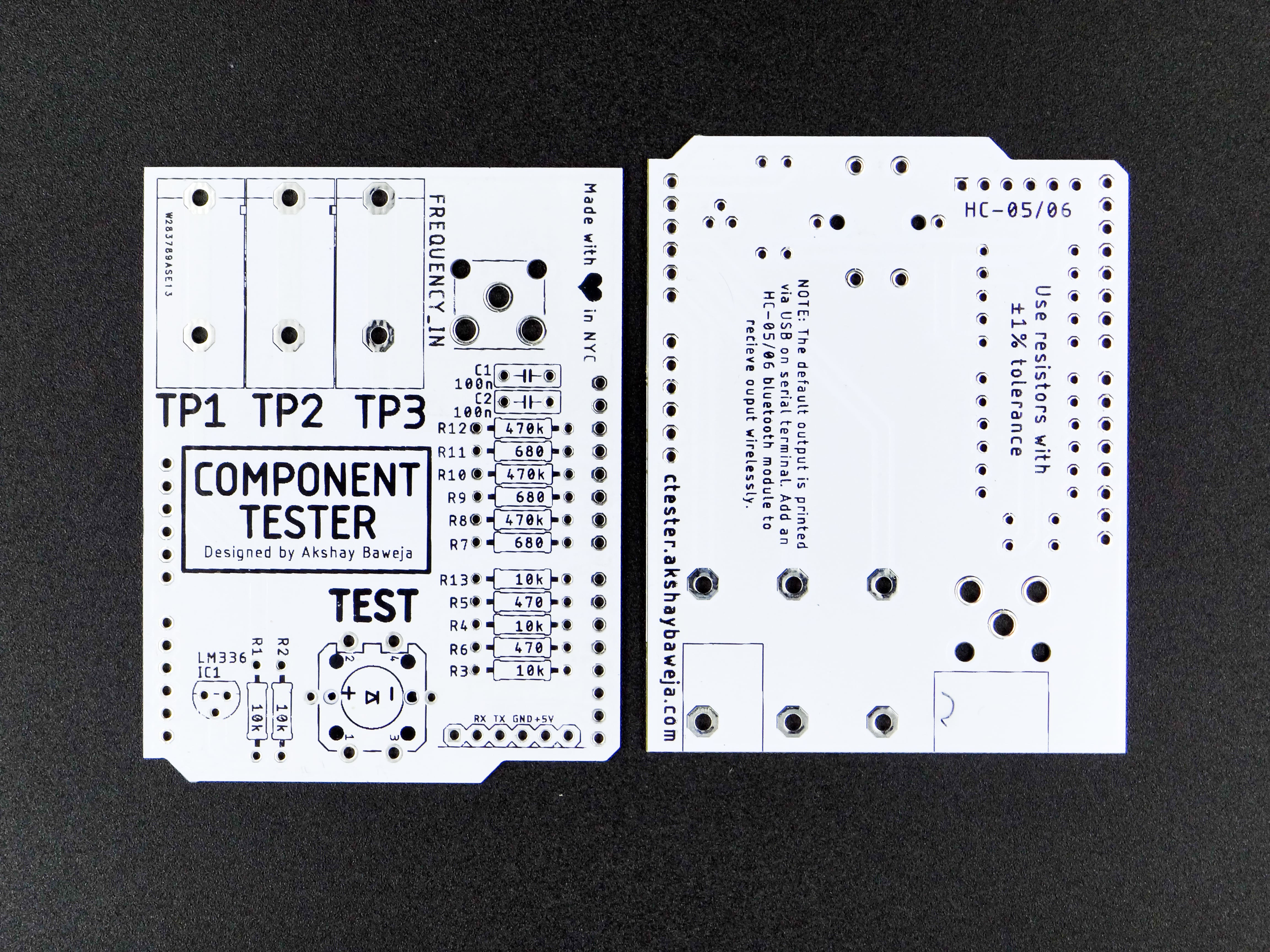
I used Autodesk Eagle to design the circuit board for the project. You will find schematics and design files in files section. Alternatively, you can also go to PCBWay (redirects you to the project ordering page) to directly order your high-quality boards.
-
2Soldering Them One by One...
![]()
⚠️ Always remember - "If it smells like chicken you're doing it wrong" ⚠️
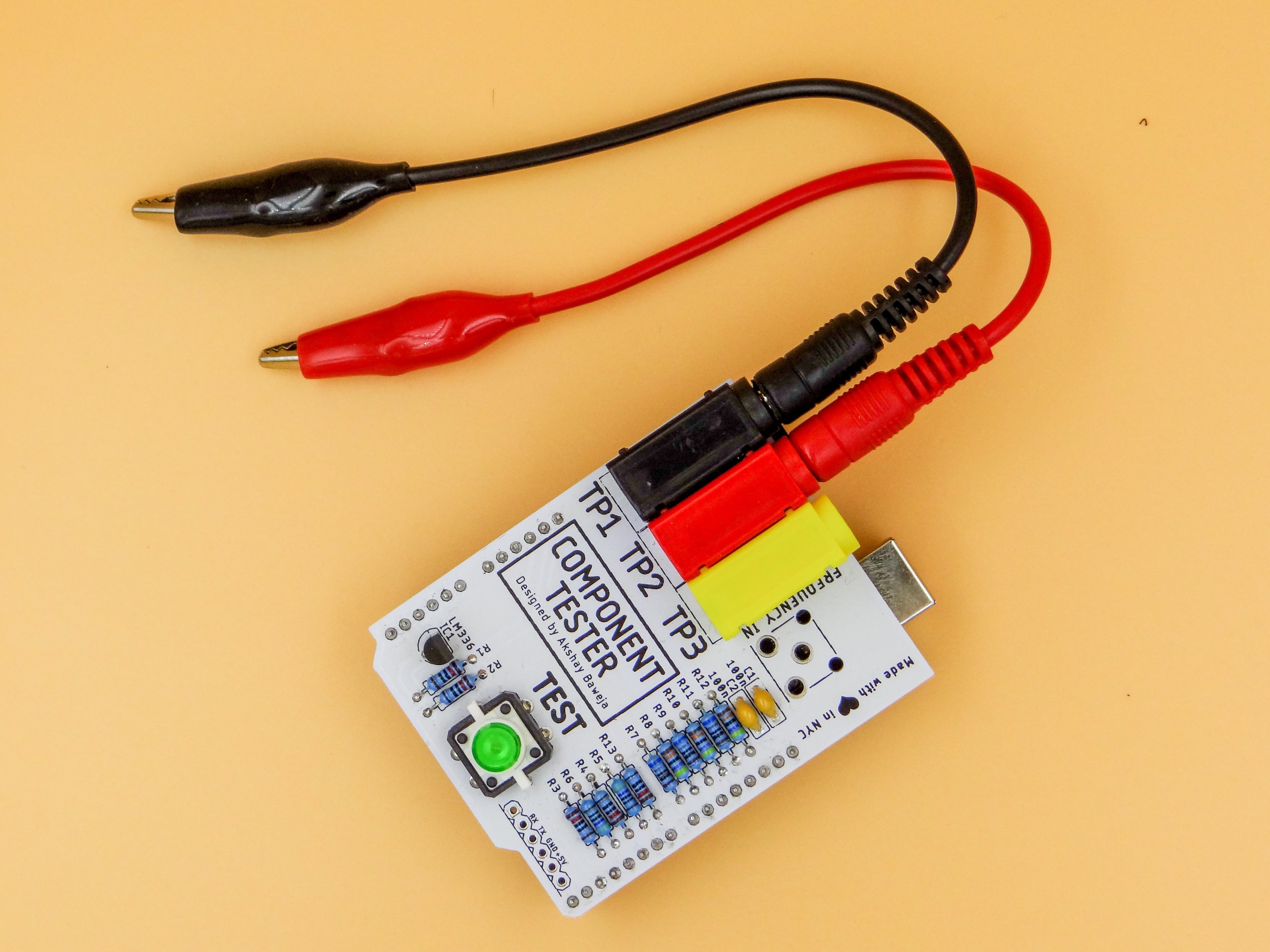
To begin with soldering I started out by soldering the resistors and capacitors first followed by the button and transistor. Followed by the 4mm banana jack binding post and male headers. Following the above mini-steps while soldering will make it easier for a neat looking board without lose or hanging components.
-
3Uploading the Firmware
Follow the instructions in the video to upload the firmware. The code is available at Project's GitHub repository.
Commands -
make allmake flash
-
4Testing 3️⃣...2️⃣...1️⃣...!!
![]()
- Hook up any component of your choice to the test leads.
- Connect UNO to PC
- Open Serial Monitor in Arduino IDE
- Baud Rate - 115200 bauds
- Press the TEST button on the board
You'll see the test results popping up on your Serial Monitor :)
![]()
-
5Tadaaaaaa You Made It
![]()
Wooohoooooo!!
You've made your own DIY Arduino UNO compatible Component Tester 🎉🎉🎉
 Akshay Baweja


Discussions
Become a Hackaday.io Member
Create an account to leave a comment. Already have an account? Log In.