 Simon Wirz
I'd like to have a defined interface connector for connecting the tools so I haven't to rewire if I'd like to change to a new process/tool. In addition I'll be able to store the tools not needed with the complete wiring harness and can quickly change tools on the fly. Therefore this interface uses the max. amount of connection pins required for all intended manufacturing processes.
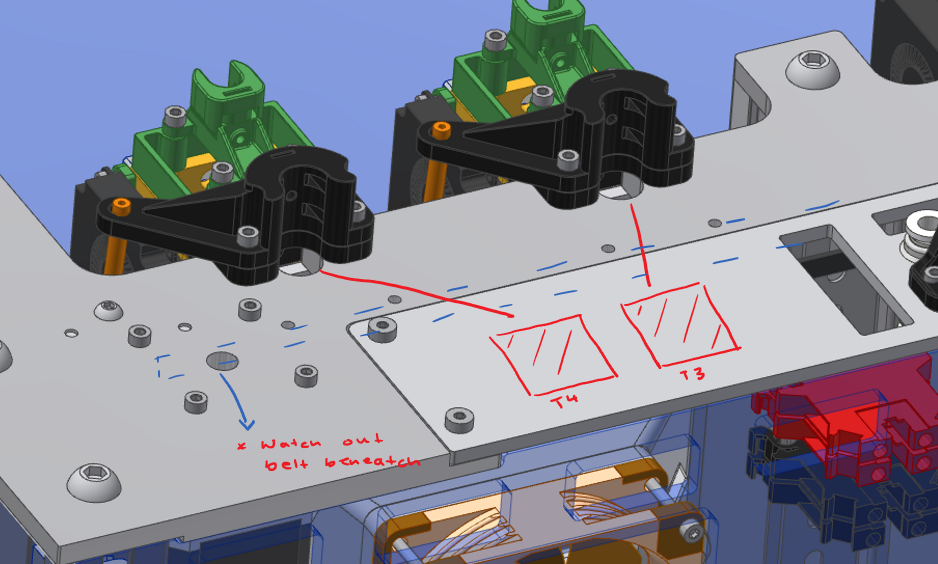
The placement:
I'd like to switch the position of the connectors to the modular part of the printer (the screwed modular plate at the back, slightly brighter gray plate in the picture below). This would allow to test different kinds of connectors without remanufacturing the actual motion system (that's actually the purpose of this modular plate).
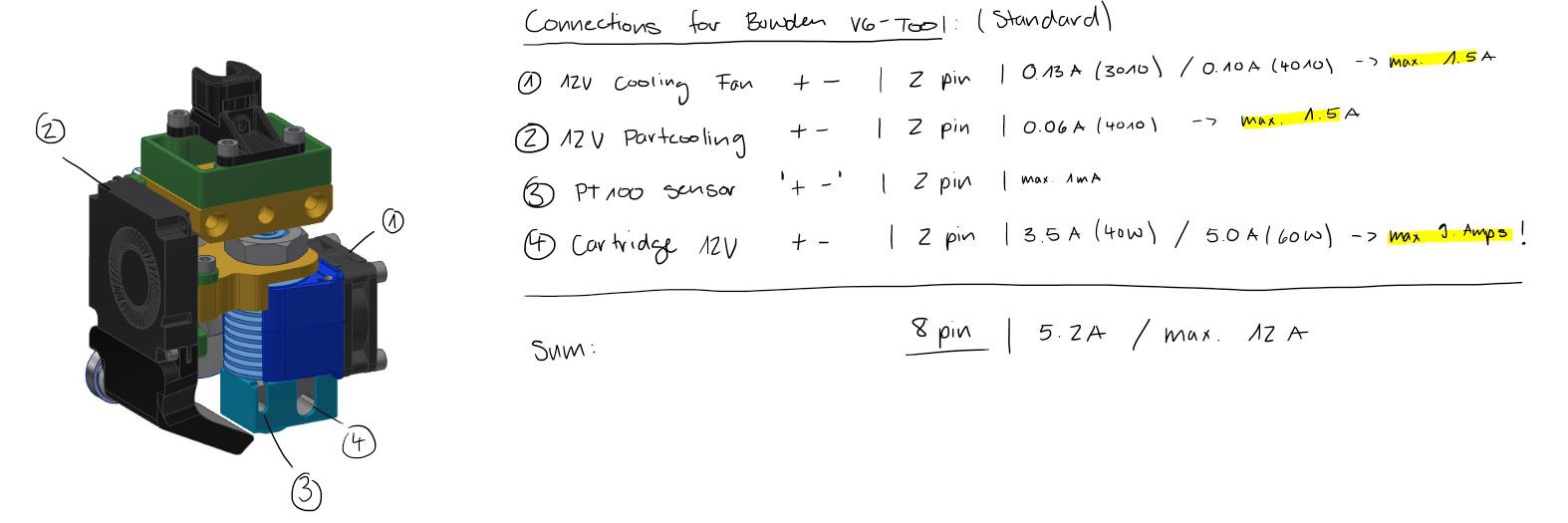
The connectors required:
V6-Bowden-Tool
Directdrive-Tool (still WIP):
PCB-Milling-Tool (still WIP):
Tool identification:
I'd like to use some NFC-tags to identifiy the current tools in the individual parking slots. On one hand I see which tools are currently in the printer and I'll be able to perform some checks like:
- Process-type (milling, picking, printing, inspection)
- Nozzle diameter (specific to printing)
- fan-types (specific to printing)
- etc
The NFC readers are therefore placed at the back of the parking slots and are communicating directly with the Duet Board (or maybe to an arduino and than to the Duet, we will see). The NFC tag is on the tools and can be easily programmed by a smartphone. You can also read the information if you don't know the exact specification (as example if you're using a titan heatbreak) or even the usage of the tool (theoretical).
Discussions
Become a Hackaday.io Member
Create an account to leave a comment. Already have an account? Log In.