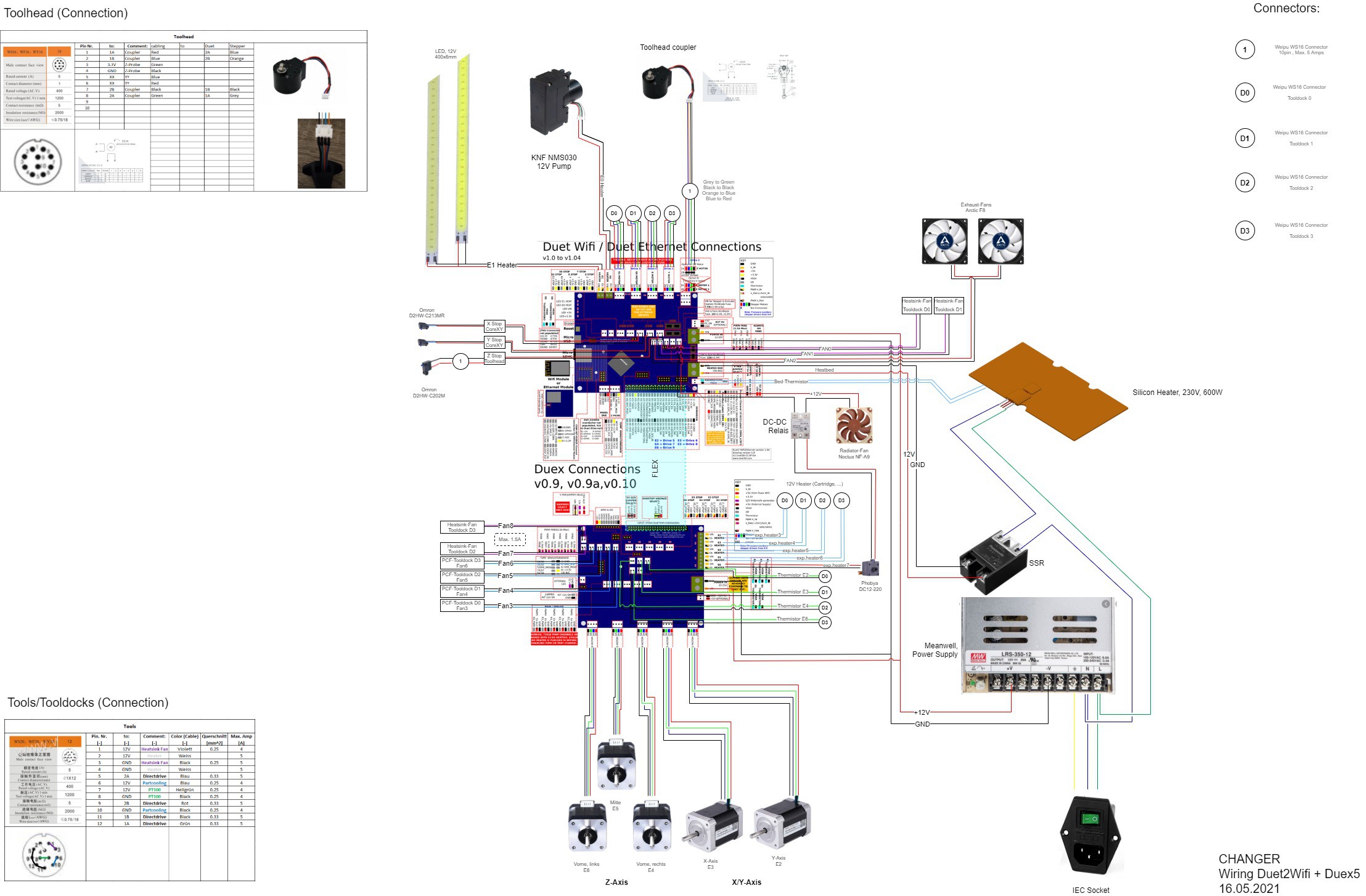
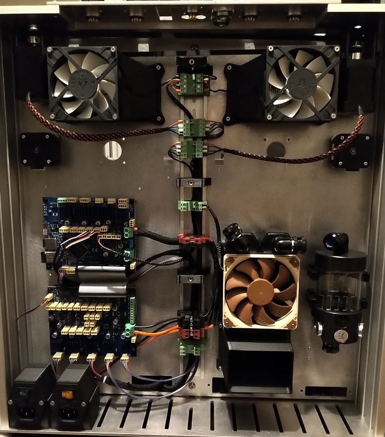
Next to the motion system all the auxillary components such as fans, airpumps and watercooling-system have to be connected and configured in the config.g of the Duet2Wifi.
The wiring illustrated:
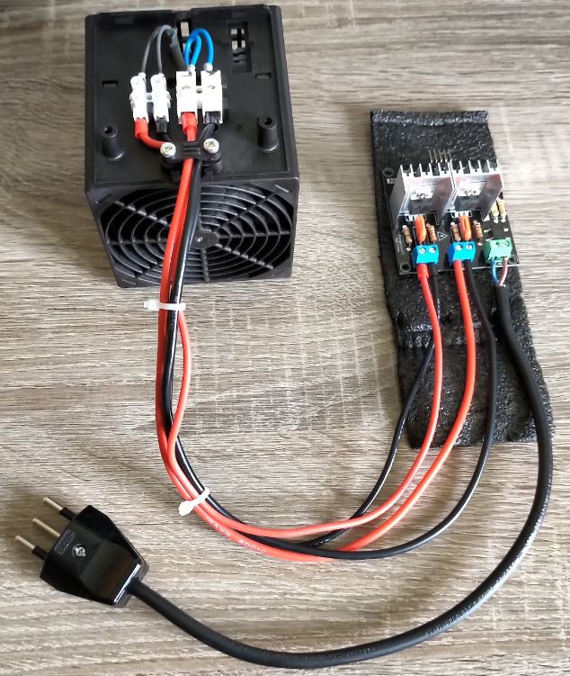
Because of the limited FAN and Heater-Outputs I had to control the radioator-fan of the watercooling loop with a SSR so the radiator switches on when the waterpump is switched on as well.
The fan configuration in config.g (RFF3...)
According to the ''wiring diagramm'' from above the configuration is the following:
M950 F0 C"e0heat" ; Air-Pump on E0-Heater-terminal M950 F1 C"e1heat" ; LED-Light on E1-Heater-terminal M950 F2 C"fan2" ; Exhaust-Fans (2 parallel) on Fan2 M950 F3 C"duex.fan3" ; Partcooling Fan Tooldock D0 M950 F4 C"duex.fan4" ; Partcooling Fan Tooldock D1 M950 F5 C"duex.fan5" ; Partcooling Fan Tooldock D2 M950 F6 C"duex.fan6" ; Partcooling Fan Tooldock D3 M950 F7 C"!exp.heater7" ; Watercooling-Pump on E6-Heater (Duex5) M950 F8 C"fan0" ; Heatsink Fan Tooldock D0 on Fan0 (Duet2) M950 F9 C"fan1" ; Heatsink Fan Tooldock D1 on Fan1 (Duet2) M950 F10 C"duex.fan7" ; Heatsink Fan Tooldock D2 on Fan7 (Duex5) M950 F11 C"duex.fan8" ; Heatsink Fan Tooldock D3 on Fan8 (Duex5)
The shown configuration section was just for initial testing and won't be like this in the end. We're working currently on a software concept to use the RFID-Chips to write and adapt the config.g file so the printer basically configures itself according to the tools on the CHANGER. In the near future if you insert a direct drive tool the E steps, driver current etc. are set automatically in the config.g file.
With this said the pins doesn't need to adress a heatsink fan or a partcooling fan in the end. It could be anything controllable with 12V.
Like already mentioned I'm using the Toolhead from the E3D-Toolchanger and I'm quite happy with this decision. The overall mechanism works like a charm and the stall detection of the coupler works flawlessly until now.
Altough the E3D-Guys are quite skilled mechanically I think the design of the cover and the cable management could've been done a little bit more thoughtful and with a proper design statement. So here we are with a neat cable solution and a custom Toolhead-Cover with underlines the industrial look of such a coupling-system (always my opinion).
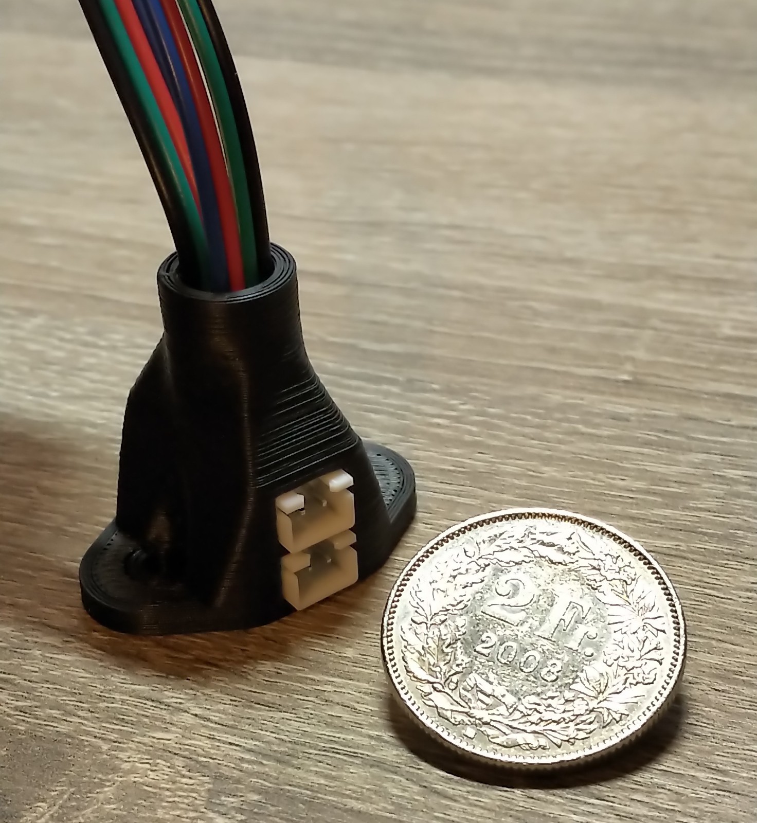
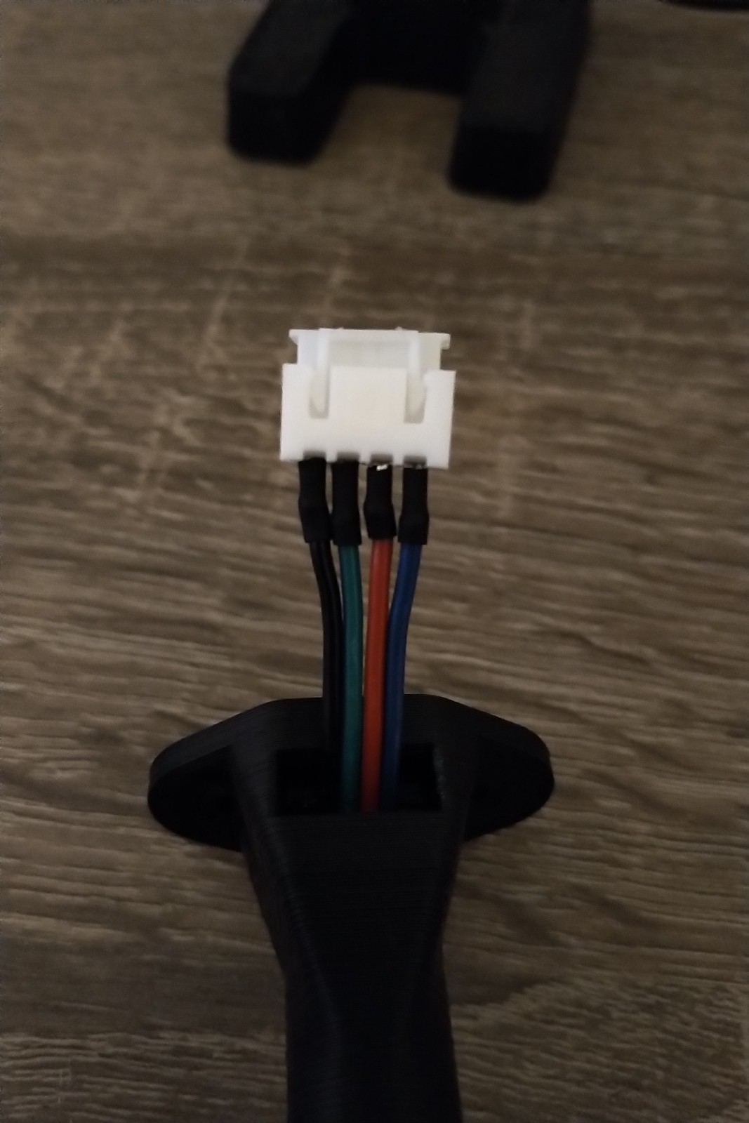
The toolhead-cabling
For the Toolhead I've designed a small 8pin-Connector and cable housing so you can just plug/unplug the coupler and the Z-endstop-switch. 2pins are not defined yet but already implemente. Maybe a toolhead light or additinal 2pin sensor...
The toolhead cables are directly soldered to a XH2.54 Terminal and then glued in place.
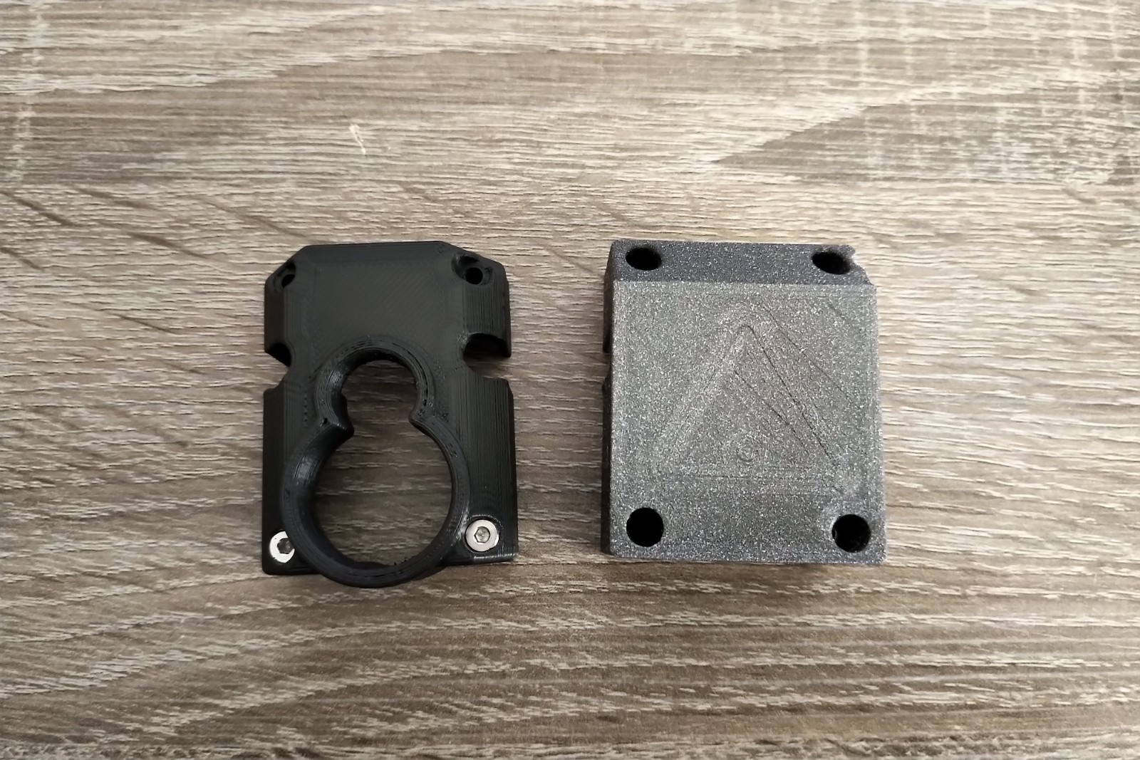
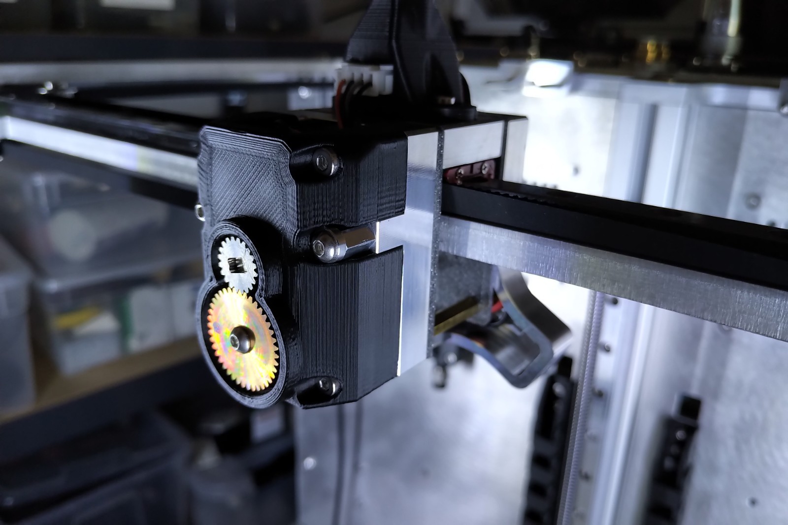
The Toolhead-Design (Cover):
For the Toolhead I've designed a new cover. Above the comparison between the E3D-Cover vs. the new one
Personally I've found it quite pleasing to see the gears of the coupling mechanism. Additionally you're able to see if the coupler is locked or unlocked. The toolhead-cover mounted looks quite nice and gives a proper statement.
The last three months I was able to build the first prototype to a proper state. I'm trying to give you a short overview over the build process over the last couple of months so you'll get a feeling of the hole build process involved.
The current state in words:
- Frame complete
- Motion system working with all endstops required
- All Fans working (exhaust fans, radiator fans)
- Watercooling pump working
- LED Light integrated and working
- Homing procedures successfull, Toolhead-coupler as well
- True bed leverling (G32) is working as well (best Milestone until now)
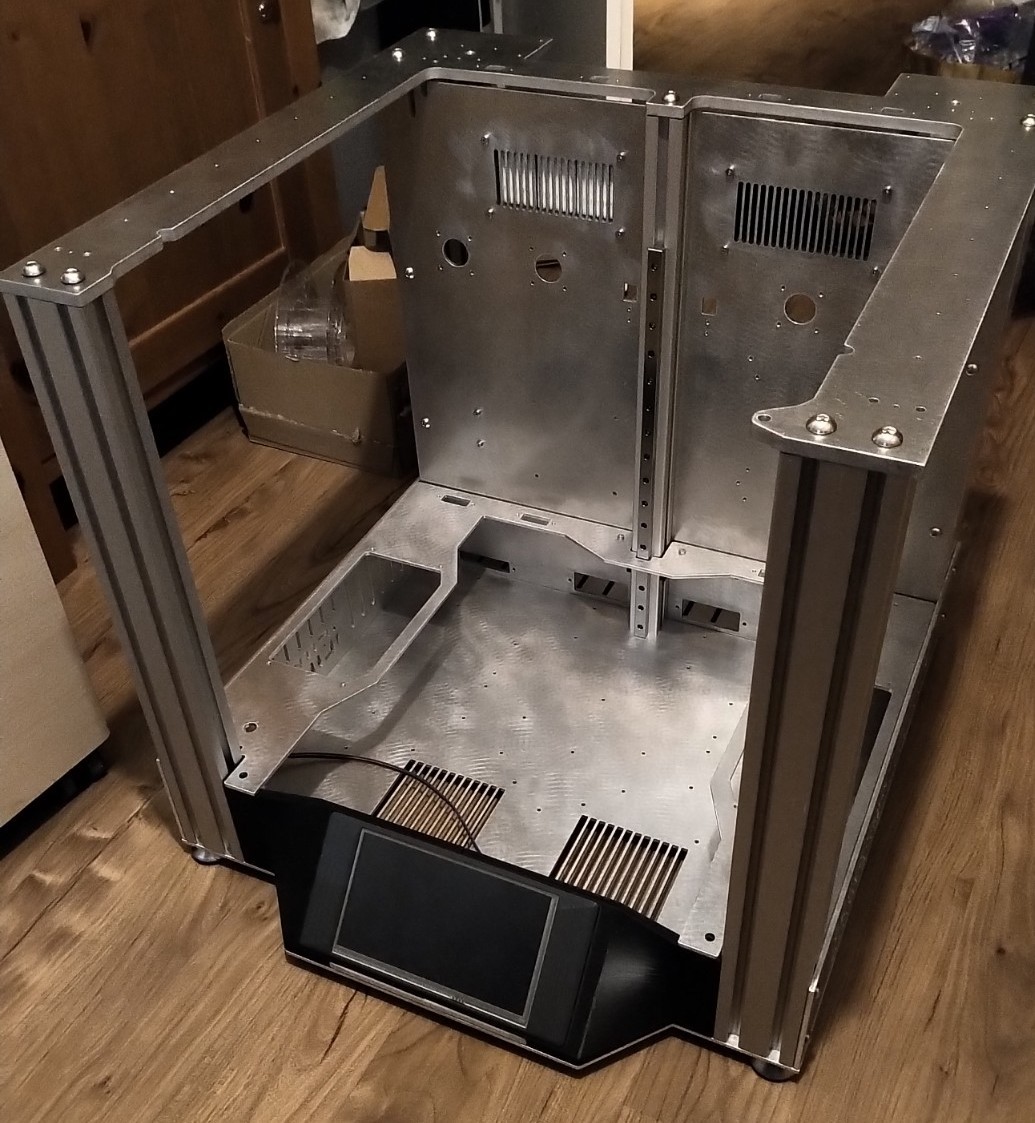
The build:
All the profiles and sheet metal plates could be mounted quite easily. First I had to thread all screw holes which took probably 2-3 hours.
For the proper alignment I've used a large precision angle. Without such a large angle you're having probably quite the struggle to proper align the frame because of it's size. First I've used the middle extrusion for reference and tightend the backpanel. Of course you'll have to align in both directions (90°). With the backpanel (3 extrusions) fixed you can mount the top plate (CoreXY-Plate) and start to align the two extrusions at the front. Because of the independend Z-Axis setup you'll have to align the hole range of motion of the z-axis otherwise the kinematic coupling will jump out if not properly aligned. This process took me around a hole day.
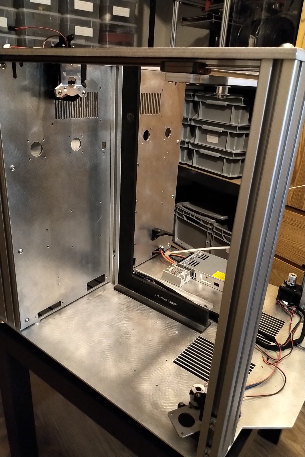
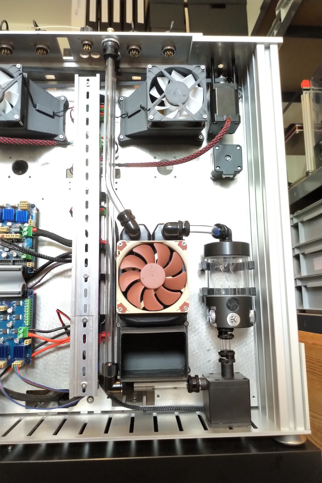
The electronics:
Next up the electronics. I've designed the printer so you can use proper DIN-Rails for tidy cable management. After the installation I'll love the idea of the simplicity and expandability. In the picture you can see three black parts with a metal insert in the middle. These are for a second DIN-Rail in a second level. The first level ist for main-electronics and therefore essential and the second layer is for the cabling of the Toolheads etc.
The watercooling:
For the watercooling loop I've tried to use proper hardtubes (PC-Casemodding) to have a proper cooling loop. I'm quite happy with the result of my first hardtubing. I've used PETG-tubes with a silicon core to bend the pipes over a heatsource. the silicon core helps to get an even bending without kinks.
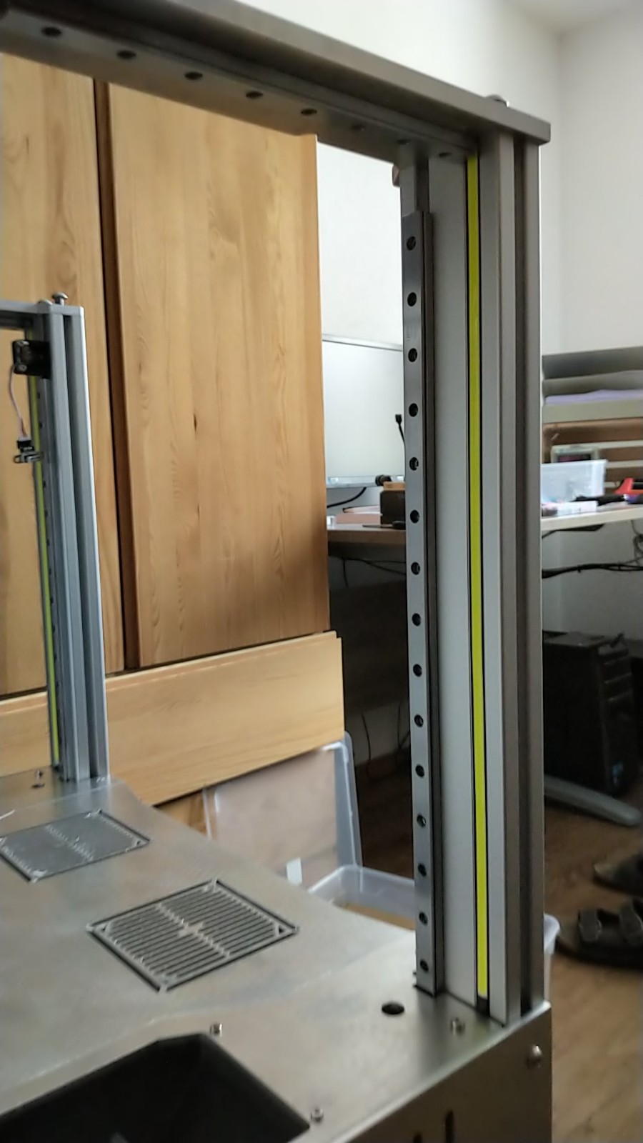
LED-Lighting:
A proper lighting concept can work in your favor regarding the overall printer appearance. I've implemented long LED-Bars inside of the both extrusions in front. Therefore I've printed proper LED-Holders for the extrusions.
The led-lighting can be switched on and off and you can reduce the brightness. The light is so bright you can't look from the back at the printer but you see every detail. Personally I think the lighting is perfect for such a printer.
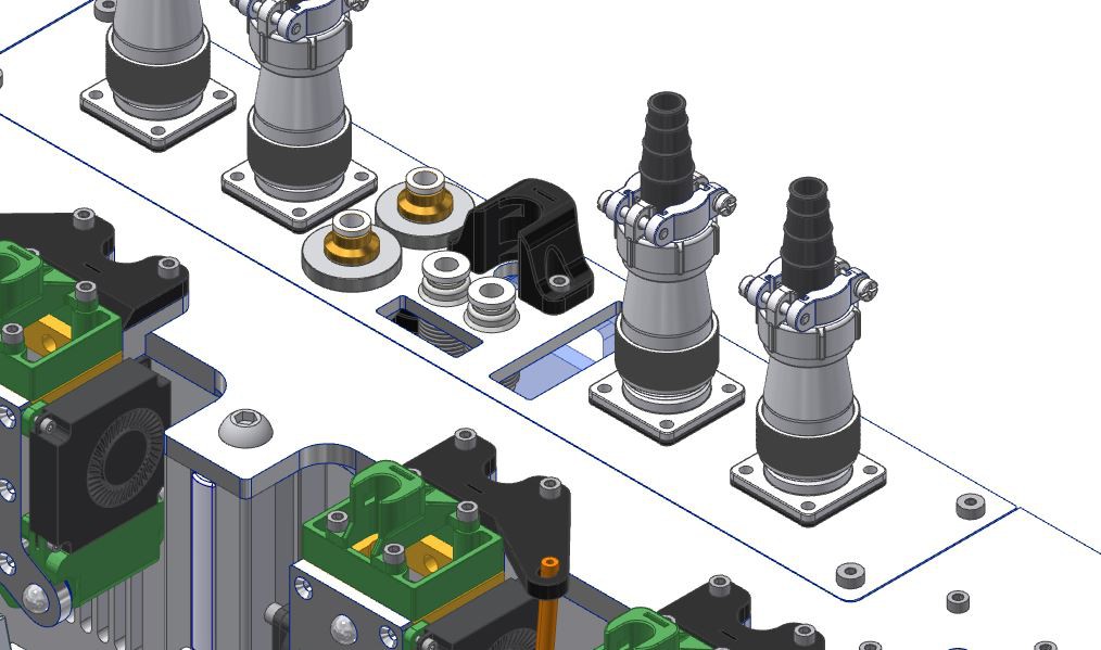
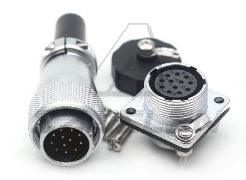
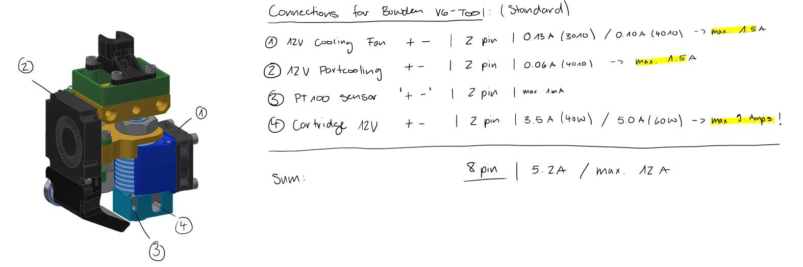
A few logs ago I talked about the defined interfaces for a quick connector. The bowden setup needs 8 pins for connection. The direct drive configuration will need 12 pins. I've decided to use industrial screw connectors with a 5 amp rating per phase. You could go larger (10amps) but the connector will be huge and 5 amps are just enough for a 60W cartridge (12V).
The costs for 4 Connectors with flange are about 30 USD. The connector itself should be around 5-6 USD for each toolhead. It isn't the cheapest solution but I think it's a proper solution.
Because I wasn't able to control the ptc element with the AC dimmer I've decided to continue the testing. This time I will test various fan speeds and measure the chamber temperature. The ptc element will run at 100% load.
Testing:
The test setup from the previous test (testlog from 20.10.2020) as a reminder. The only difference in this test will be the ac dimmer between the fan and the 230 mains voltage.
Test setup, illustrated
The test setup consist of a cardboard box (volume of 0.088m^3) with three 100K temp. sensors.
Sensor T: Located at the top/back of the box, should be a hotspot (temperature rise)
Sensor B: Centered in the middle of the box
Sensor C: Attached to the housing of the heater fan
The exhaust opening is constant throughout the test. The log process remains the same (rampsboard and excel post processing).
Results/Experience:
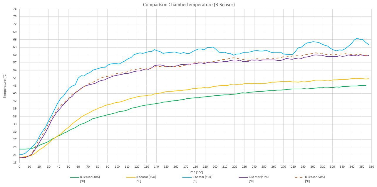
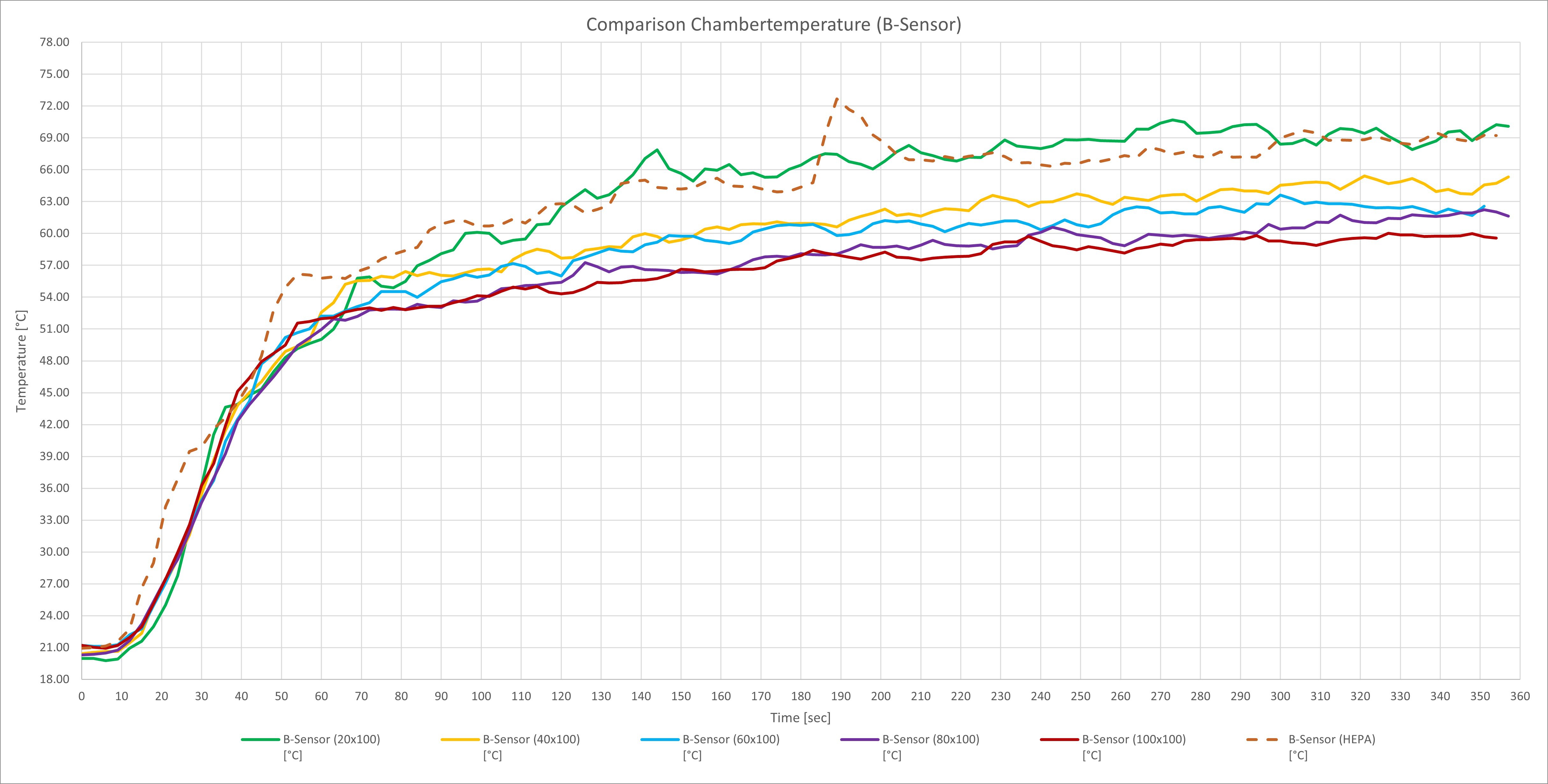
I was able to show that it isn't necessary to control the heating element to then control the chamber temperature. For the sensor in the middle (sensor B) are the results:
Like you would expect the temperature rises depending on the fan speed. But keep in mind that I've only tested for 6 minutes and the temperature (30%, 35%) does not seem to be stabilized. But it seems that the amount of air at the intake exeeds the amount of air at the outtake between 35% and 40% because of the delta T of 16°C (high temperature rise) and the suddenly flat gradient of the curve at 40%. The systems seems ''saturated'' at 40% because a further increase of the fan speed doesn't result in a higher chamber temperature.
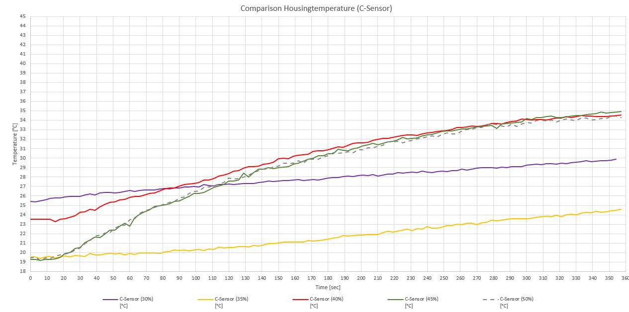
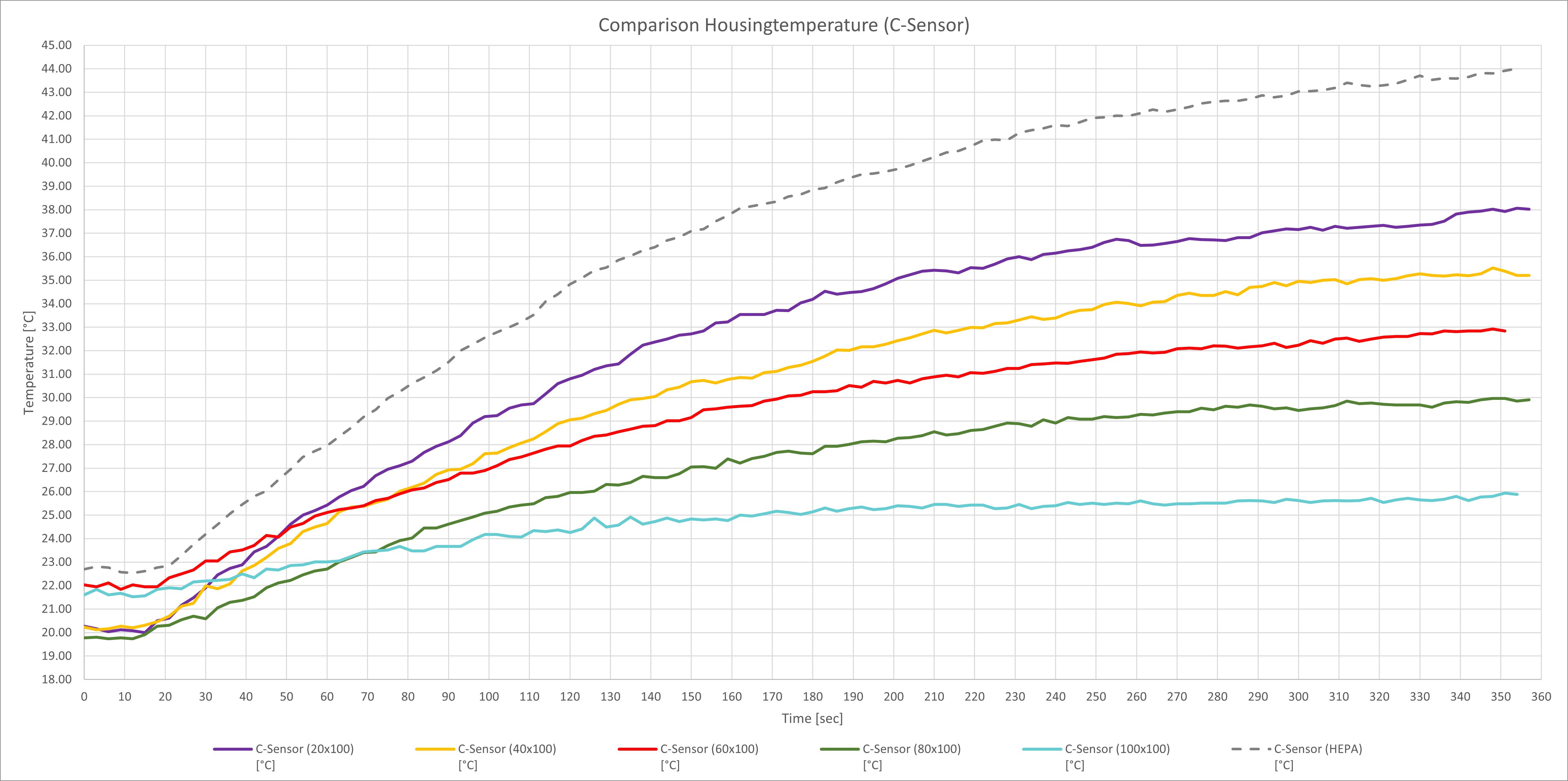
For completeness the results of the housing temp (sensor C):
This graph shows the same behaviour. The intersection of the 30% and 35% is due to the different starting temperature. The gradient of the two curves are nearly the same.
Like I've mentioned in the previous testing of the industrial heater unit STEGO CS028 400Watt (230V) I'd like to test the ability to control the heater unit with a TRIAC Dimmer. The heater unit consists of a normal 230V Fan and a PTC heater. The fan is easy to control however I'm not sure about the ptc element heater. Maybe I'll face some frequency problems
TRIAC-Dimmer:
For controlling the AC fan and the AC ptc element I've ordered the TRIAC-Dimmer from RobotDyn.
RobotDyn, 2 Channel, AC Dimmer
Test-Setup:
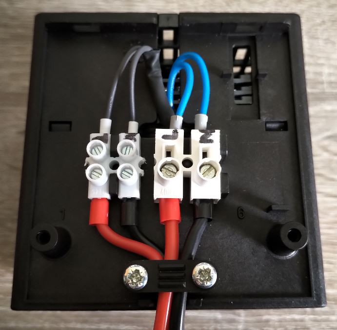
First you'll have to separate the ptc element and the fan. Originally the two elements are wired together (Weco connector) so both run of the same power source.
The fan and the ptc heater are then connected to the RobotDyn 2Channel AC-Dimmer. We're talking about mains voltage (230V!) so keep that in mind and in case of doubt please check back with an electrician or abort.
Controlling the TRIAC-Dimmer:
For controlling the TRIAC-Dimmer I'm using an arduino Nano and connected the pins as following:
The controlling of the 230V fan works just fine. I'm able to control the speed and even turn off the fan. I've measured the voltage and noticed that the fan starts spinning at 30% (which equals 111V) and reaches the max speed at approx. 65% (which equals 229V). If you increase the speed even more the fan will begin to stall. Because of this ''strange'' range of 30 to 65% you can use the map function to adjust these values. Something like map(fan, 0, 100, 30, 65).
The problem:
When I try to control the ptc element as well suddenly I can no longer control the fan speed. The fan just stalls independent of the value (30 to 65%). I even switched the connectors on the mains side to check if the TRIAC-Dimmer is fully functional. The fan standalone works in both ways and quickly starts to stall I've a try to use the ptc element parallel. I noticed that the element gets warm so maybe there isn't enough capacity available for heating AND the fan. Or maybe that's because of the characeristics of this ptc elements? If you have an idea I'd love to hear from you in the comments.
I will investigate this behaviour in the near future and keep you updated.
I'd like to have a defined interface connector for connecting the tools so I haven't to rewire if I'd like to change to a new process/tool. In addition I'll be able to store the tools not needed with the complete wiring harness and can quickly change tools on the fly. Therefore this interface uses the max. amount of connection pins required for all intended manufacturing processes.
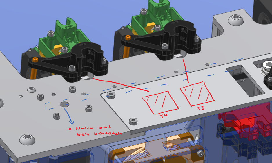
The placement:
I'd like to switch the position of the connectors to the modular part of the printer (the screwed modular plate at the back, slightly brighter gray plate in the picture below). This would allow to test different kinds of connectors without remanufacturing the actual motion system (that's actually the purpose of this modular plate).
The connectors required:
V6-Bowden-Tool
Directdrive-Tool (still WIP):
PCB-Milling-Tool (still WIP):
Tool identification:
I'd like to use some NFC-tags to identifiy the current tools in the individual parking slots. On one hand I see which tools are currently in the printer and I'll be able to perform some checks like:
The NFC readers are therefore placed at the back of the parking slots and are communicating directly with the Duet Board (or maybe to an arduino and than to the Duet, we will see). The NFC tag is on the tools and can be easily programmed by a smartphone. You can also read the information if you don't know the exact specification (as example if you're using a titan heatbreak) or even the usage of the tool (theoretical).
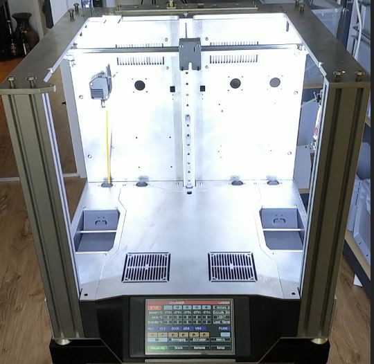
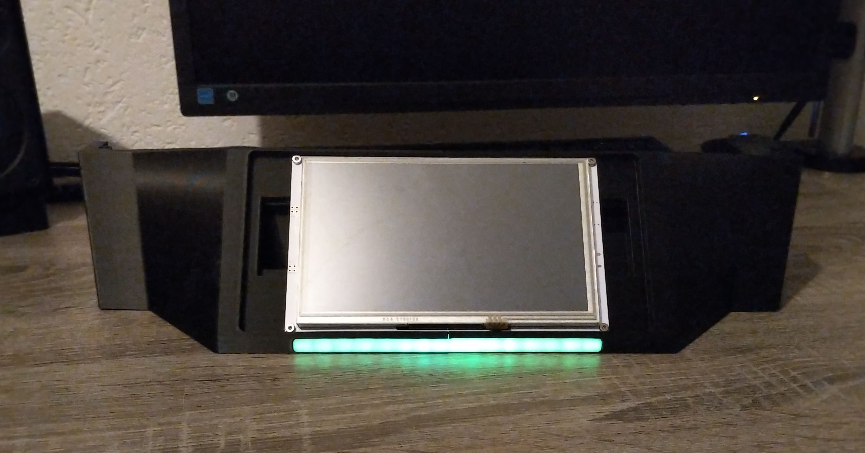
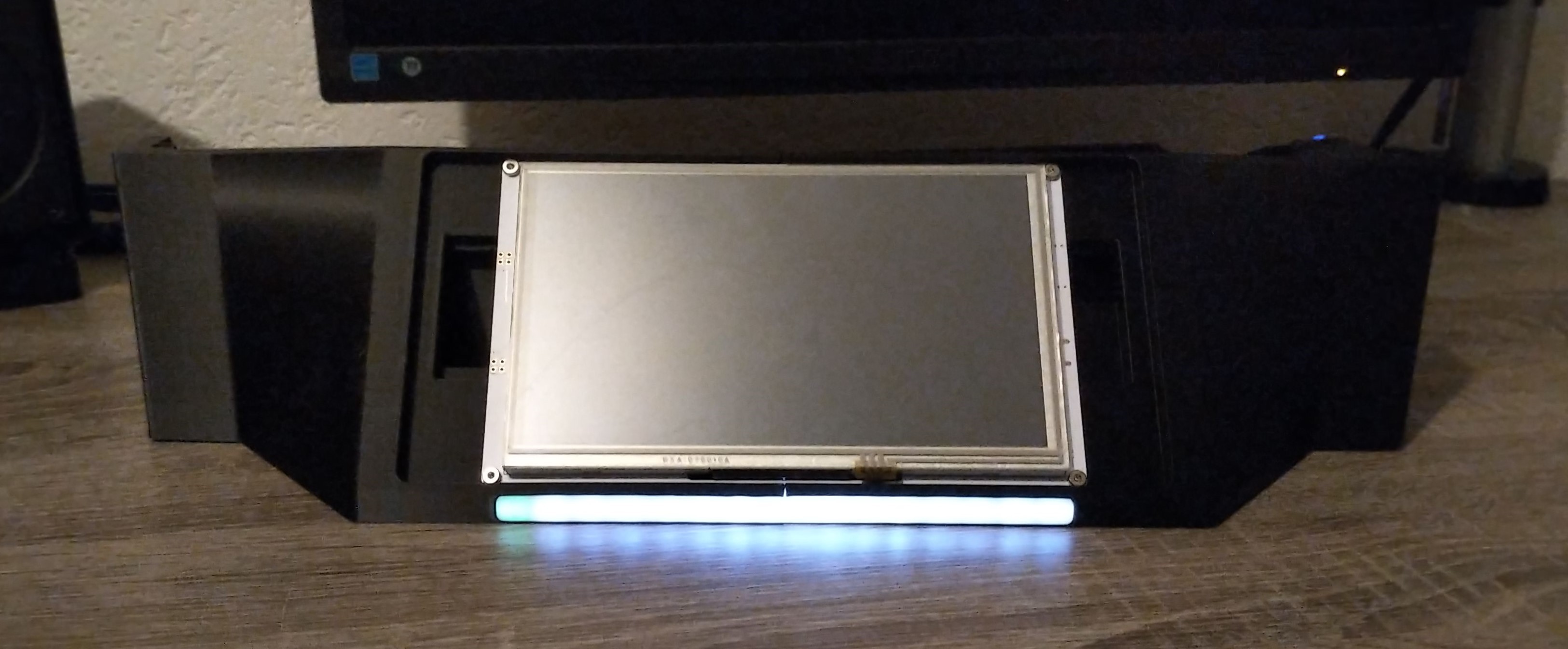
I've always liked the light indications of modern cnc machines (red: error , green: working , orange/yellow: paused, manual operation etc.) and wanted to implement this feature in my toolchanger design. I'm using adressable LED's so it possible not just to show the overall status with red, green and yellow. The 16bit LED-bar allows to show the printing procress in 6.25% time increments. Therefore the LED's switch incrementally from white to green (based on the estimated print time).
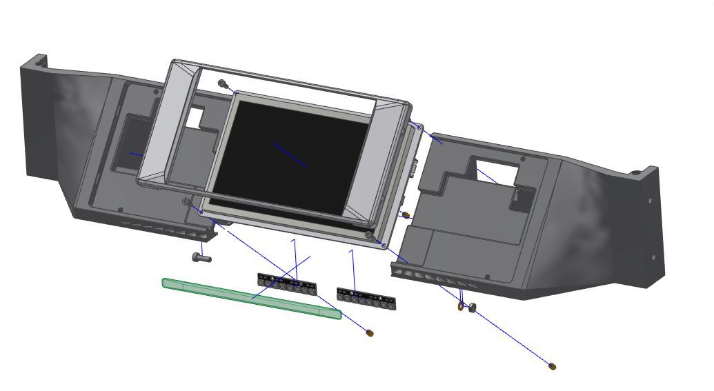
The Frontpanel assembly:
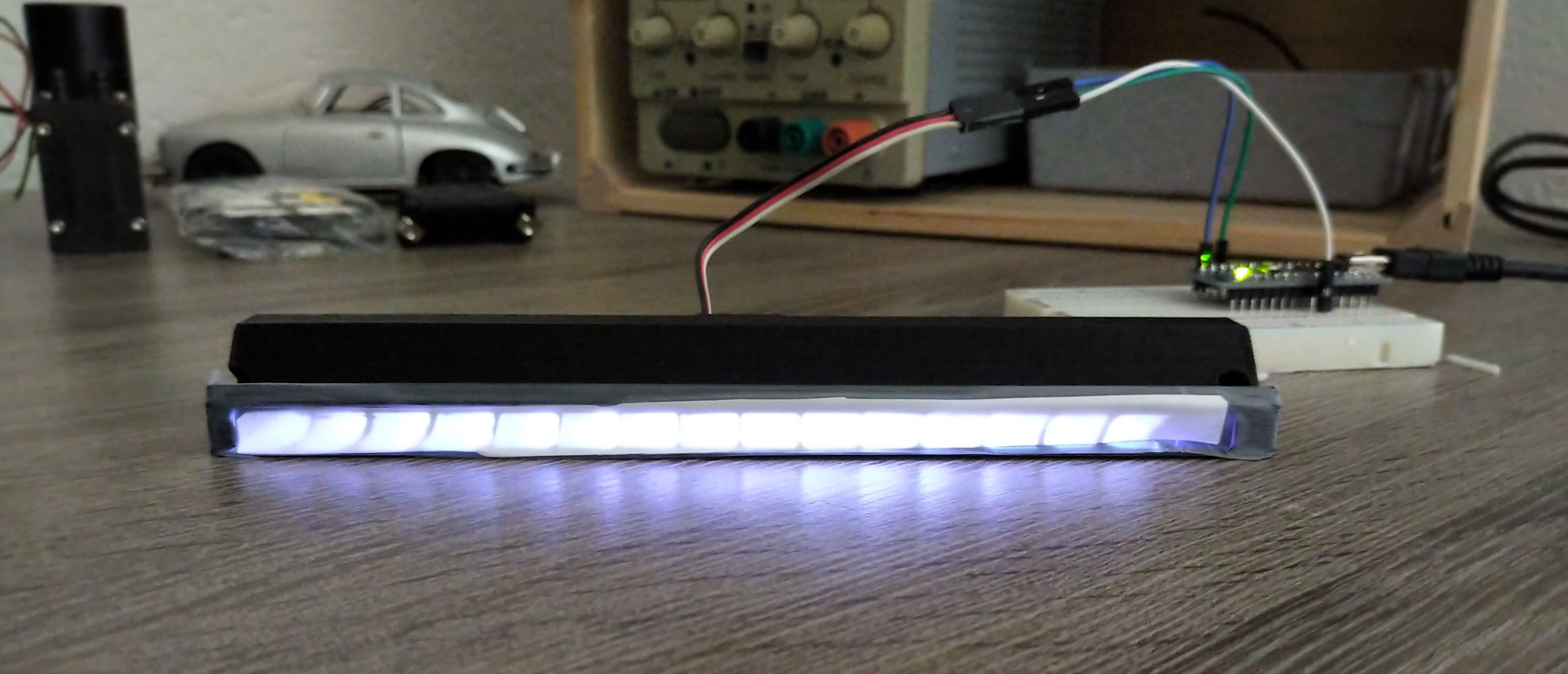
As you can see the actual status bar at the front is significantly longer than the actual 16bit-LED (2x 8Bit WS2812). Therefore I had to test the homogeneity with the brightness.
The subcomponent test: Paper as diffusor, all LED's at full brightness
For proof of concept I've used paper and tape to see if the light ''channels'' even work.
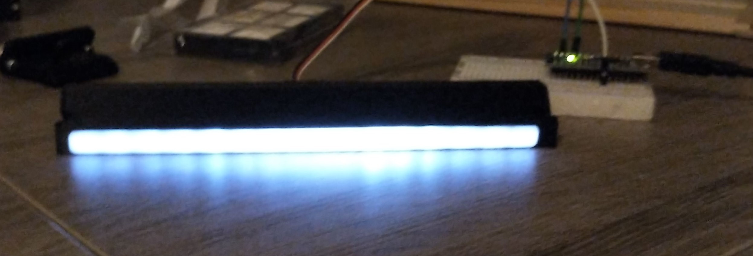
PLA-Diffusor, all LED's at full brightnessThis picture shows the mentioned problem with the homogeinity. The LED's in the middle have the shortest way and therefore shine the brightest. The outer LED's have a quite long and curved channel to pass before hitting the diffusor.
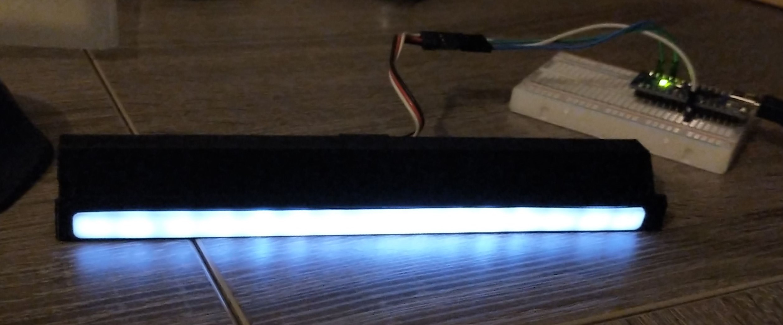
PLA-Diffusor, individually adressed brightness
To improve the homogeinity I've adressed the LED's individually and set the brighness for better appearance.
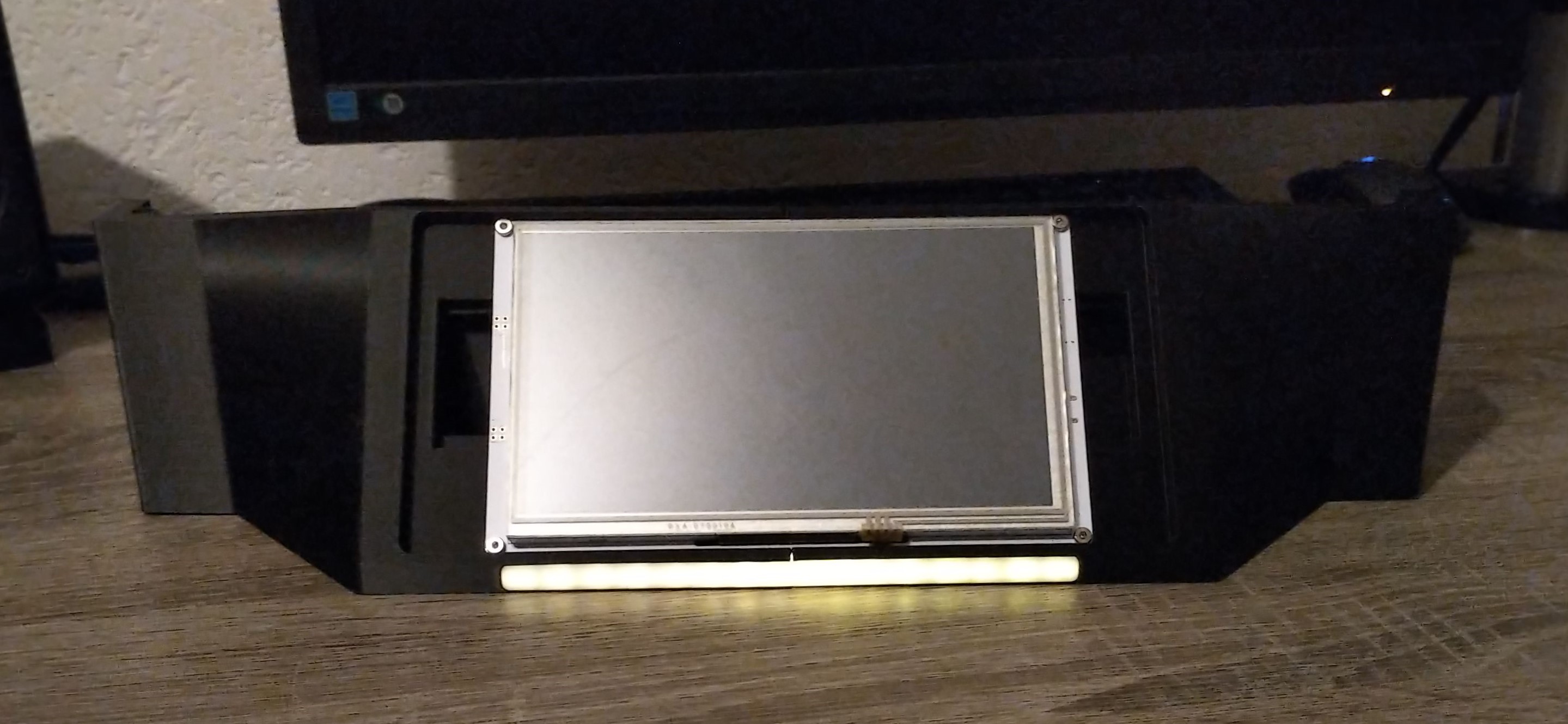
Testing other colors with the front panel:
Frontpanel, Yellow/OrangeFrontpanel, GreenFrontpanel, White and Green-progressThe Quick&Dirty Code for the progress bar:
for (int i = 0; i < NUMPIXELS; i++) { if (i <= 2 || i > 12) { pixels.setPixelColor(i, pixels.Color(255, 255, 255)); pixels.show(); // This sends the updated pixel color to the hardware. delay(delayval); // Delay for a period of time (in milliseconds). } else { if (i == 3 || i == 12) { pixels.setPixelColor(i, pixels.Color(130, 130, 130)); pixels.show(); // This sends the updated pixel color to the hardware. delay(delayval); // Delay for a period of time (in milliseconds). } else { if (i == 4 || i == 11) { pixels.setPixelColor(i, pixels.Color(100, 100, 100)); pixels.show(); // This sends the updated pixel color to the hardware. delay(delayval); // Delay for a period of time (in milliseconds). } else { if (i == 5 || i == 10) { pixels.setPixelColor(i, pixels.Color(50, 50, 50)); pixels.show(); // This sends the updated pixel color to the hardware. delay(delayval); // Delay for a period of time (in milliseconds). } else { if (i == 6 || i == 9) { pixels.setPixelColor(i, pixels.Color(40, 40, 40)); pixels.show(); // This sends the updated pixel color to the hardware. delay(delayval); // Delay for a period of time (in milliseconds). } else { if (i == 7 || i == 8) { pixels.setPixelColor(i, pixels.Color(30, 30, 30)); pixels.show(); // This sends the updated pixel color to the hardware. delay(delayval); // Delay for a period of time (in milliseconds). } } } } } } } }
Implementation:
For the implementation in the Duet-Firmware I will write a class ''LED_Color'' and use the arduino Nano as a slave which just receives the task ''Green'' , ''Orange'', ''Red'' and ''Status''. The actual code isn't done yet.
I'd like to print high temperature materials like PEKK, PEEK. Therefore I've implemented a watercooling system to keep the hotend cold which also allows the printer enclosure to be heated. I've searched a long time for a professional solution. I've found some compact heater fans which are used to heat control cabinets. STEGO Elektrotechnik GmbH offers some high quality heater fans in different options.
The CS028 Series:
STEGO CS028
I've decided to test the STEGO CS028, 400W, 230V Version and MURRPLASTIK AG Schweiz kindlysent me one to support this project. This heater uses a PTC-Element and therefore it is quite a safe way to heat your chamber. When the temperature rises the resistance increases as well and therefore the current decreases. With this configuration you'll have a safe thermal runout protection. On the other hand you have the disadvantage of a high switching current at lower temps (remember the ptc-element). An active control of the heating temperature could be difficult because of the fast on/off-switches. This heater fan also includes a integrated heater fan (230V) which (right now) is directly wired to the heating element and therefore can't be controlled in speed. So the only simple way to control the temperature in the heating chamber is to controll the exhaust airflow.
Testing:
Test setup, illustrated
The test setup consist of a cardboard box (volume of 0.088m^3) with three 100K temp. sensors.
Sensor T: Located at the top/back of the box, should be a hotspot (temperature rise)
Sensor B: Centered in the middle of the box
Sensor C: Attached to the housing of the heater fan
To simulate various exhaust airflows I've cut a rectangle with 20mmx100mm, 40x100mm, 60x100mm, 80x100mm, 100x100mm in the top plate of the cardboard. I've started with 20x100 and increased step by step. I even used a HEPA-Filter (the one used in the roomba cleaners) but without a fan attached to suck the air out (I feared a backlog but tried it anyway)
For sensing the temperature I've used a Rampsboard with an Arduino Mega and configured Marlin 1.19 with an additional temperature input (heated_chamber). For logging I've used Pronterface. If you click on ''debug communications'' you'll get approx. all 3 seconds a status report which looks like:
For filtering this message I than used excel to get the T:XX , B:XX, C:XX in seperate rows to finally plot the results and make some calculations (time to reach 60°C, max. deviation between Sensor T and B etc.).
The results/experience:
Comparison of Sensor B (middle of the box)
Comparison of Sensor C (housing temperature of heater fan)
The results show what you would expect i've youre going to increase the exhaust airflow. The max. temperature decreases and it takes longer to heat up your ''chamber''. What's intresting you see that the HEPA-Filter and an opening of just 20mmx100mm almost results in the same behaviour. If you looking at the housing temperatures you'll see a correlation between exhaust airflow and housing temperature of the heater fan. As feared the HEPA-filter without a fan causes a heavy backlog which results in a higher temperature rise of the heater unit. Same goes for a high exhaust airflow. If youre letting a lot of the air out without any backlog the heater unit hardly gets warm. This comes at a cost of the max. chamber temperature (which is logical).
I did some measurements.
Time to reach 60°C with sensor B (middle of the box):
20x100mm: 96 seconds
40x100mm: 162 seconds
60x100mm: 168 seconds
80x100mm: 240 seconds
100x100mm: 327 seconds
Hepa-Filter: 87 seconds
Max. reached temperature with sensor B
20x100mm: 70°C
40x100mm: 65°C
60x100mm: 63.5°C
80x100mm: 62°C
100x100mm: 60°C
Hepa-Filter: 73°C (peak at 190seconds, caution)
Conclusion:
The tested heater unit is high quality made and can be used to quickly heat up a chamber with a volume of 0.09m^3. Because of the mentioned switching problems (high current peaks) the temperature can be controlled over the exhaust airflow BUT this comes at a cost of max. temperature. The heater unit is limited by design to a max. temperature and can't get any hotter ( I believe 80°C). If I want to reach a higher temperature I have to limit the exhaust airflow to a minimum this means the current design of the printer needs insulation and sealings at the door which contradicts my design philosophy of the printer. For the next step I'd like to test the heater unit with actively control the fan speed at a defined exhaust opening.
 Simon Wirz