-
Kit prices are going up
07/06/2016 at 07:59 • 0 commentsAs noted, very few updates here, now when the project has its own web site at www.liteplacer.com. Anyway, the kit prices are going to go up. Full details at the newsletter: http://eepurl.com/b7QgR9
-
Kits are shipping
03/28/2015 at 10:51 • 0 commentsAll pre-orders are shipped and there are kits in stock at www.liteplacer.com
-
Project Completed!
02/03/2015 at 18:29 • 0 commentsProject first stage is now completed and this is the last update on this site. Further announcements and updates will be at projetcs own website at www.liteplacer.com. At that site you can find tons of info, build instructions, software (including source code), support forums and more. See you there!
The development will continue, but further reports and support will be on www.liteplacer.com. Thank you Hackaday.io for this! I am grateful for this site, but it is time to move on.
-
Last update for the year
12/31/2014 at 14:17 • 1 commentYay! As far as I know(*), I got the technical part of the project done by the end of the year. In other words, the loose parts placement works as well:
![]()
These were loose parts from a box. I placed these at a spot where the machine can see them, roughly (+-45deg.) in 0 orientation. The machine looked at them, figured out where exactly they were and how much rotated and placed them. As far as I know, no other pick and place machine does this. (I wouldn't be too surprised to find out of one, though.)
*: No doubt I'll find something to improve and correct when I test the system some more before releasing it. But for now, I'm not aware of any issues and the software is feature complete for version 1.0.
Early next year I'll finish the documentation and open a web site for the project. You can build your own, and there will be kits.
-
December Update
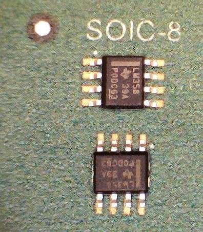
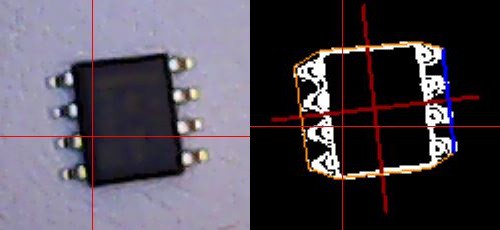
12/20/2014 at 14:11 • 0 commentsOk, it's been a while; sorry about this. I haven't update the logs since I fell off the competition, but that does not mean I lost interest to the project, quite the contrary! The project is almost completed. The hardware has been fine for a few months by now. The only function missing from the software is loose parts placement: We all have parts in our parts bins, and the machine should be able to place those too, without complicated trays or jigs. And I already have the optical part routine done:
![]() Should be simple from here. :-) It would have been nice to get the software fully done before holidays; that almost happened. But right now, I don't have time to even shoot a video, I'll be away with the family soon.
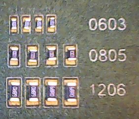
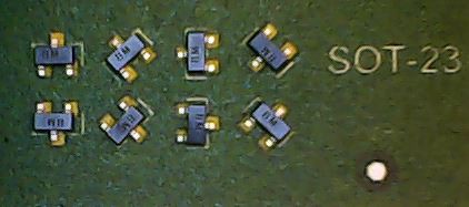
Should be simple from here. :-) It would have been nice to get the software fully done before holidays; that almost happened. But right now, I don't have time to even shoot a video, I'll be away with the family soon.Placement results are not that bad. During development, I use printed images of a PCB instead of real boards. Much cheaper and faster. The downside is that in the pictures below, it looks crappy. Here are some resistors (0603 is 0.8mm x 1.6mm) and SOT-23's. At least some of the placement inaccuracies are because the parts are not always located in the middle of their pockets. But anyway, there would be no problem in reflowing those, so the goal of being able to handle 0603's is met. Hmm, I have to try 0402s... (See below!)
![]()
![]()
You can see the crappy alignment mark; real boards would likely be even better. The optical calibrations are nice; there are no special requirements in building the machine, the camera and image processing do accurate homing, machine squareness alignment, PCB location, scaling, shear and rotation alignment*, needle wobble compensation, finding parts** and so on.
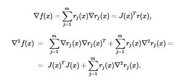
*: From alignment marks measurements, deriving the transform from CAD coordinates to machine coordinates turned out to be surprisingly hard problem. It sounds like something that anybody who was awake on college math classes could do. But in fact, only the third mathematician I hired for it could actually do it! No kidding, this just one image form an explanatory article he gave me to explain his code:
![]()
Fortunately the algorithm works, I don't have to debug it! :-) The nice advantage in using an advanced algorithm here is that the PCB doesn't need to be very precise. My laser printer has about 0.2% positive gain error in X and about the same but negative in Y. Doesn't matter. In other words, home made boards will be fine. The PCB placement doesn't need to be accurate either, no special jigs are needed. It is enough that the alignment marks are found roughly where expected.
**: The tape sprocket holes are an easy task for the image processing.
Early next year, I'm going to finish the documentation. I'll post the link to the site when it is presentable. I will show you how to build and use the machine, where to download the software and source code etc. Stay tuned!
Happy holidays!
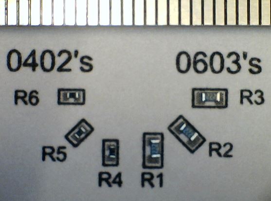
Update: I couldn't resist, so I did try 0402s:
![]()
The scale above is mm's; the 0402parts are 1.0 x 0.5mm. Paradoxically, the results are even better with 0402s than with 0603s. That is because with the resistors I have, the 0603 tape has relatively looser pockets than 0402 tape. This is likely vendor specific. Anyway, these would still reflow jjust fine. The conclusion is that my machine can handle at least 0402s easily. I'm happy.
-
Calibration functions and video
08/20/2014 at 18:25 • 0 commentsJust hours to the semifinals deadline! I received the motors and adapted the calibration routines for this hardware version. As noted, the final hardware design will still change in some minor details. Nothing that affects finishing the software, though.
I made a video showing how the cameras are used in calibration; see the side bar. The mechanical switches are surprisingly accurate, but since we have cameras, we should use them! I'm happy with the accuracy, in the 0.02mm range.
-
Concept video done, some progress, some mishaps
08/12/2014 at 16:03 • 0 commentsJay! Normally, not a worth a shout, but there were some technical issues... I still have no sound on my videos exported from my iPhone, but fortunately, I got my old camera working. I know I have a heavy accent, but if you don't understand what I'm saying, just enable the subtitles. :)
Also, the wiring is done. Unfortunately, Murphy ordered my stepper motors and they are not the precision 0.9 deg./step type, but the regular 1.8deg./step. Only one letter difference, but from the previous prototypes, I know I need the precision in order to do 0402's and down. So, actual placement videos need to wait for DHL. Next week, I suppose.
I also downloaded the Sysrtem Design documents, so I think I now have all the official requirements done. Another jay!
-
June 2014
07/04/2014 at 08:20 • 0 commentsStatus right now
I need to get the official entry for the Hackaday competition filed before the August deadline, so that is what I'm doing. The third prototype looks good (a photo is provided), but does not have wiring or the electronics components installed. The software is unchanged from the previous log entry - as said, finishing it needs the third prototype to be up.
Next weeks
Next few weeks will not see any progress, it is our summer vacation with my lovely wife. If I'm very lucky, I can show the machine picking and placing some components at the August video, but I'm not holding my breath for that. :(
Next months
I haven't signed up any projects at my main job for the rest of the year. I'm getting this project finished and the web shop for the kit opened. All looks good, there is not that much remaining.
-
Status before Hackaday.io
07/04/2014 at 08:10 • 0 commentsFirst prototype, spring 2013
On one hand, it was promising. It showed the feasibility of the build and proved, that the desired accuracy would be possible to achieve. On the other hand, it was about impossible to calibrate, certainly much more difficult than I could assume an average builder could do. And since the aim has been from the beginning to share the machine, this wasn't good. Further, slightest miss-alignment resulted stress to the bearings. In fact, the prototype died before I could get very much done on the software side. Back to the CAD.
Second prototype, autumn 2013
Much better, and actually works (or at least did work before I took it down, see later). I hadn't thought some details through and it showed. Also, a couple of non-fatal design mistakes needed some improvisation. Overall, I was happy about it, although a third design round was needed. The photo with the green carpet shows the second prototype detached from its table.
Software, winter 2013-2014
I'm using Visual C#, the most productive language I'm fluent with. After a false start with OpenCV (nothing wrong with that, it was mostly me) I got most of it done, using Aforge.NET vision library. In its current state, the software can kind of build boards, but I'm not happy with the overall workflow. Also, as I was adding stuff to the user interface as I went along, some parts that should be together are scattered around; time for some refactoring and finishing up. But some details about final calibration needed the (hopefully) final prototype build.
Third prototype, spring 2014
Building the third prototype took more time than I wanted to, mainly because I'm planning to offer a build it yourself kit once the project is finished. Arranging the storage of the parts, acquiring all of them and in some cases, waiting for a few months(!) of lead time was kind of frustrating. On the other hand, the time allowed me to finish off some audio projects, freeing time for finishing this project after the summer. Eventually, the third prototype got done, too. All looks good.
-
The Story
07/04/2014 at 07:46 • 0 commentsHi! My name is Juha Kuusama. All of my career, I have been an electronics product developer, most of the time on audio products. My main job is at Kuusama Audio Oy, designing high-end HiFi and home theater audio products.
Recently, I purchased equipment for my company to be able to assemble SMD circuit boards in house. That would vastly speed up the development process, not to mention saving the cost of outsourcing the assembly. I only needed the equipment for prototypes – I don’t think I would be doing more than one or two boards at the time, and I’m doing only a few new designs in a year. So, I bought about the cheapest and simplest tools there are: manual paste dispensing with a steel squeegee, a manual vacuum pick-up tool with a foot switch and a desktop grill oven with a automatic controller. Total cost was only about 300€(!), as I already had a microscope. (There is no affiliation to the products linked, other than a satisfied customer.)
I was delighted how easy to system was to set up. A couple of hours tweaking the profile on the controller, and I had the oven following the paste manufacturer’s recommended temperature profile more or less perfectly. A couple of practice runs of paste dispensing and I was ready to do the first real board.
Using a steel stencil, paste dispensing gave great results. (See the video in the first link to see how to do that – very easy!) And reflow soldering result was faultless, too. That was expected – remember, the temperature profile was correct. I was exatic about the easiness of these stages, too. Paste dispensing was only a couple of minutes, including the time cleaning the stencil afterwards. Soldering happened automatically with one press of a button. This is how prototypes should be built!
Except the stage in between! Oh my. This was the board, an ESS SABRE32 Reference 32-bit DAC module:
![Sabre-small]() Doesn’t look like much, but there are 450 SMD parts on it. Even with a good vacuum pick-up tool, that took about three hours. I was able to do it, but it was more of a hero story than how this should be done. My hand started shaking after the first hour, with two to go. Do note that after putting down the soldering paste, you only have a few hours to place the parts. I did manage to finish the placement before the paste went bad; it wasn’t that good towards the end, but fortunately, the result was great, except my hurting neck. But no, this is definitely not how this job should be done! No way I wanted to go through that again.
Doesn’t look like much, but there are 450 SMD parts on it. Even with a good vacuum pick-up tool, that took about three hours. I was able to do it, but it was more of a hero story than how this should be done. My hand started shaking after the first hour, with two to go. Do note that after putting down the soldering paste, you only have a few hours to place the parts. I did manage to finish the placement before the paste went bad; it wasn’t that good towards the end, but fortunately, the result was great, except my hurting neck. But no, this is definitely not how this job should be done! No way I wanted to go through that again.So, I started to look for a pick and place machine for prototype assembly. I am very familiar with real, production equipment, but those cost tens of thousands and need much more room than I could make available. Certainly something simpler would exist; I couldn’t be the only one wanting to do SMD prototypes in-house. To my surprise, I couldn’t find anything. I couldn’t believe it. There were some aids to support the hand on manual placement and used machines ranging from 10k an up, but nothing automatic and affordable. Especially, there was nothing aimed for prototyping and the special requirements of a prototype assembly.
On the other hand, I had been looking at low cost entry level CNC machines, such as the Shapeoko. With similar technology, building a pick and place machine can’t be that difficult, couldn’t it, especially for a seasoned product developer who knows what a prototype builder really needs*? And so, the LitePlacer project started.
*: I suspected from the beginning that I could be wrong… One of these days, I’m going to write about that!
LitePlacer - a low cost Pick and Place machine
LitePlacer is a Pick and Place machine optimized for prototype assembly. It has optical calibration with two cameras: www.liteplacer.com
 Juha Kuusama
 Should be simple from here. :-) It would have been nice to get the software fully done before holidays; that almost happened. But right now, I don't have time to even shoot a video, I'll be away with the family soon.