0%
0%
Wireless solar-powered sensor node
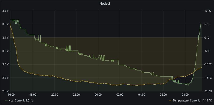
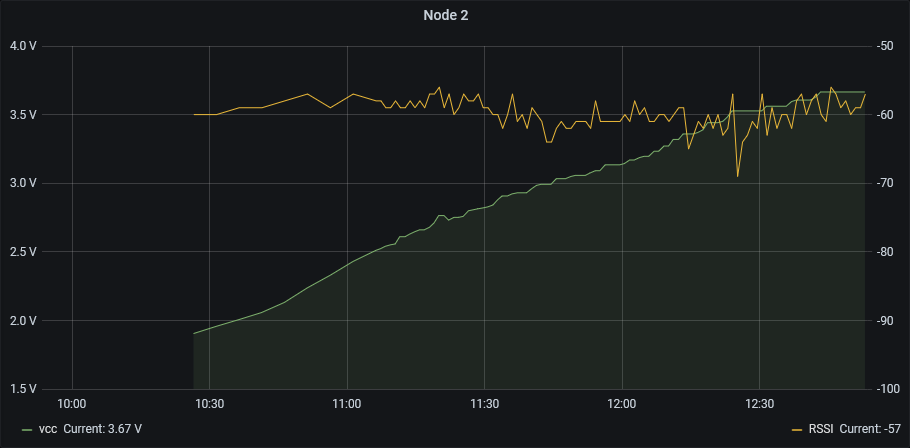
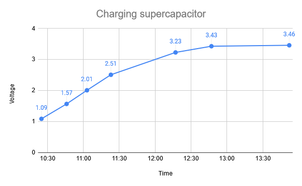
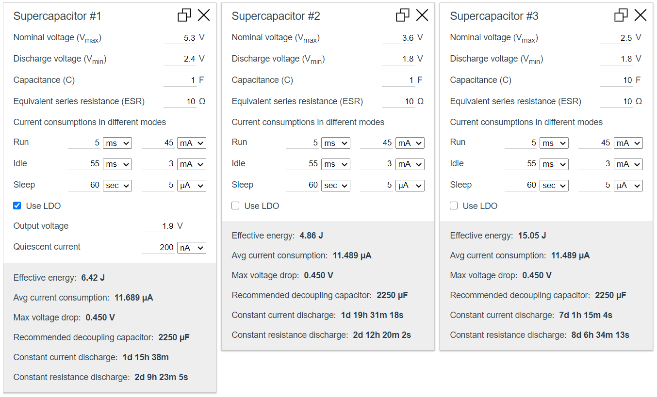
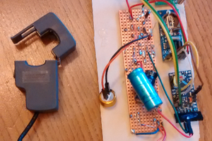
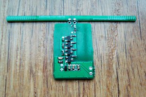
A solar-powered node that stores energy in a supercapacitor, wakes-up regularly, measures different parameters, and sends them to a gateway
 strange.rand
Become a Hackaday.io member
Already have an account? Log in.
Just one more thing
To make the experience fit your profile, pick a username and tell us what interests you.
Pick an awesome username
hackaday.io/
Your profile's URL: hackaday.io/username. Max 25 alphanumeric characters.
Pick a few interests
Projects that share your interests
People that share your interests


 Jurist
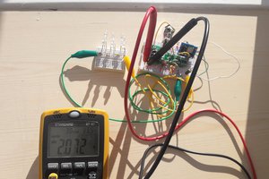

 Jan Waclawek
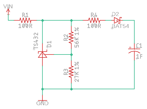
Is a really nice project, but do you have any schematics you could share to see if we can replicate it?