Thorsten Jaeger
-
OVERHAUL !!
04/01/2021 at 17:54 • 0 comments1. Moved to "SNAPZZ Bus gen.2". Essentially it's able to take all IO from an ESP32-S2 or Raspberry PICO 2040
2. I reduced to 2 Modules for now:
2.1 ESP32-S2FR based (ESP32-S2 with integrated Flash and RAM)
2.2 Raspberry 2040 Chip (i have 10 samples)
I have the PCBs, the components and the motivation. After Easter break i will
- build some prototypes for both SNAPZZ Module (ESP32 and RP2040 based)
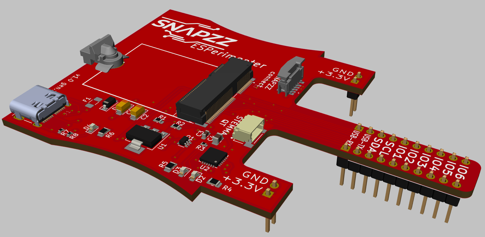
- build some prototypes for 2 Launchpads: the ESPIrimenter Breadboard adapter and the USB/40 IO adapter
(Pictures in the other Project)I got a new Microscope as well - good bye my little cheapo USB Microscope, and thanks for all the fish, and welcome KERN Stereo microscope :)
If the Prototypes work as expected i build some 10 Pilot boards and give them away for free to interested people.
-
Shrink me more !!
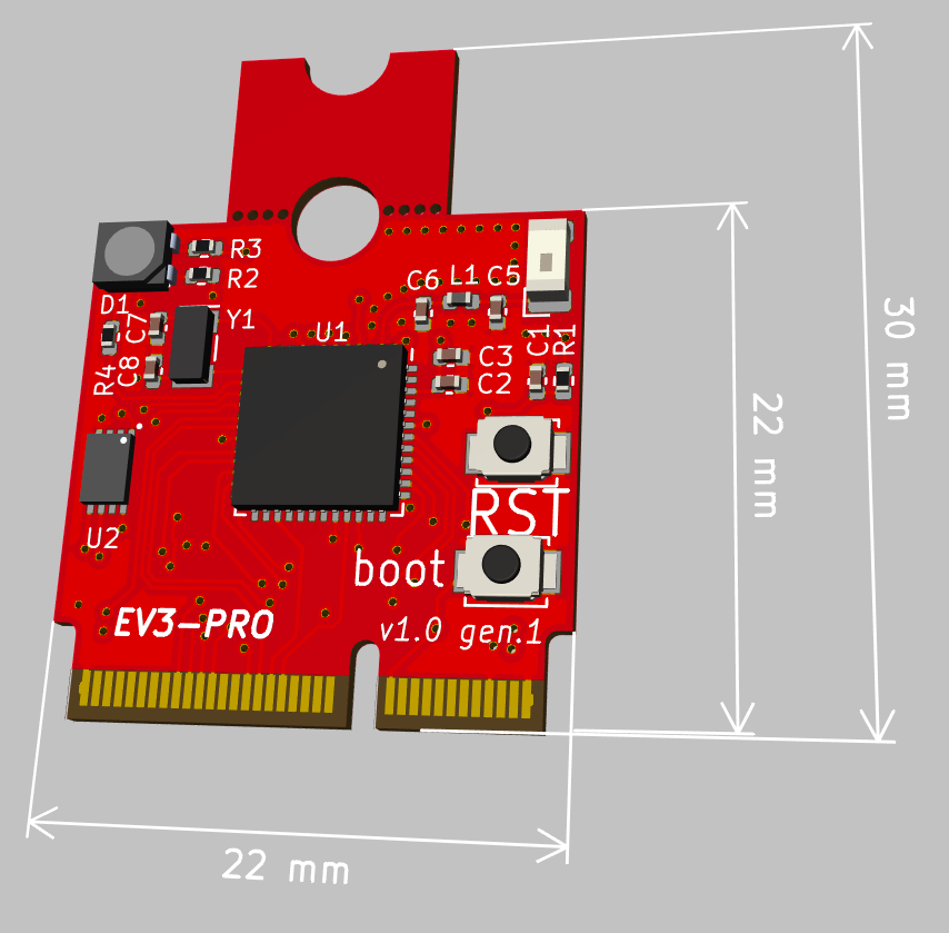
01/03/2021 at 11:46 • 0 commentsInitially the SNAPZZ Modules are 22x30mm. By extending the Chip Family i can get rid of the Flash chip and get plenty more PCB space.
This lead me to making a new size - 22x22mm. To stay compatible with the original base (mount) with 30mm lenghts i added a breakaway section. So it can be mounted in a 30mm length mount, but also in a 22mm lenghts one.
This specific board is using Espressif ESP32-pico-v3-02 Chip. It contains both Flash (2M) and RAM (4M) in the Chip.
Another name thing here is the -PRO Suffix. Essentially telling that it contains the EEPROM Chip (U2)![]()
-
Auto-detect Host connectivity
11/12/2020 at 21:49 • 0 commentsDepending on the Modules it's desired to directly strap USB D+/D- to the Module (eg ATSAMD21 or ESP32-S2) or to strap USB to a USB/TTL Chip (eg CP2102N) and send RX/TX to the Module.
Luckily i included a USB Mux chip on the Reference Base Board. The Module can tell the Mux (by pulling a pin high or low) to send Dp/Dn directly to the module or to the on-base USB/TTL Chip.
-
Adding a Quick-Lock/Release System to SNAPZZ
11/11/2020 at 13:32 • 0 commentsIn addition to the "SNAPZZ magnetic" Experiment i am looking into mechanical Lock/Release Systems. I found this tiny nice one that i can use. For ver permanent Installations, a Solder-standoff and a screw is the better choice; For Experimenting, debugging, swapping a Quick-Release Model is better.
The Module itself doesn't need a change, the Notch on Top can stay there and swapped into a Carrier board with a Screw. The Carrier Module (depending on the Quick Lock).
Modules with a SNAPZZ...
![]()
![]()
-
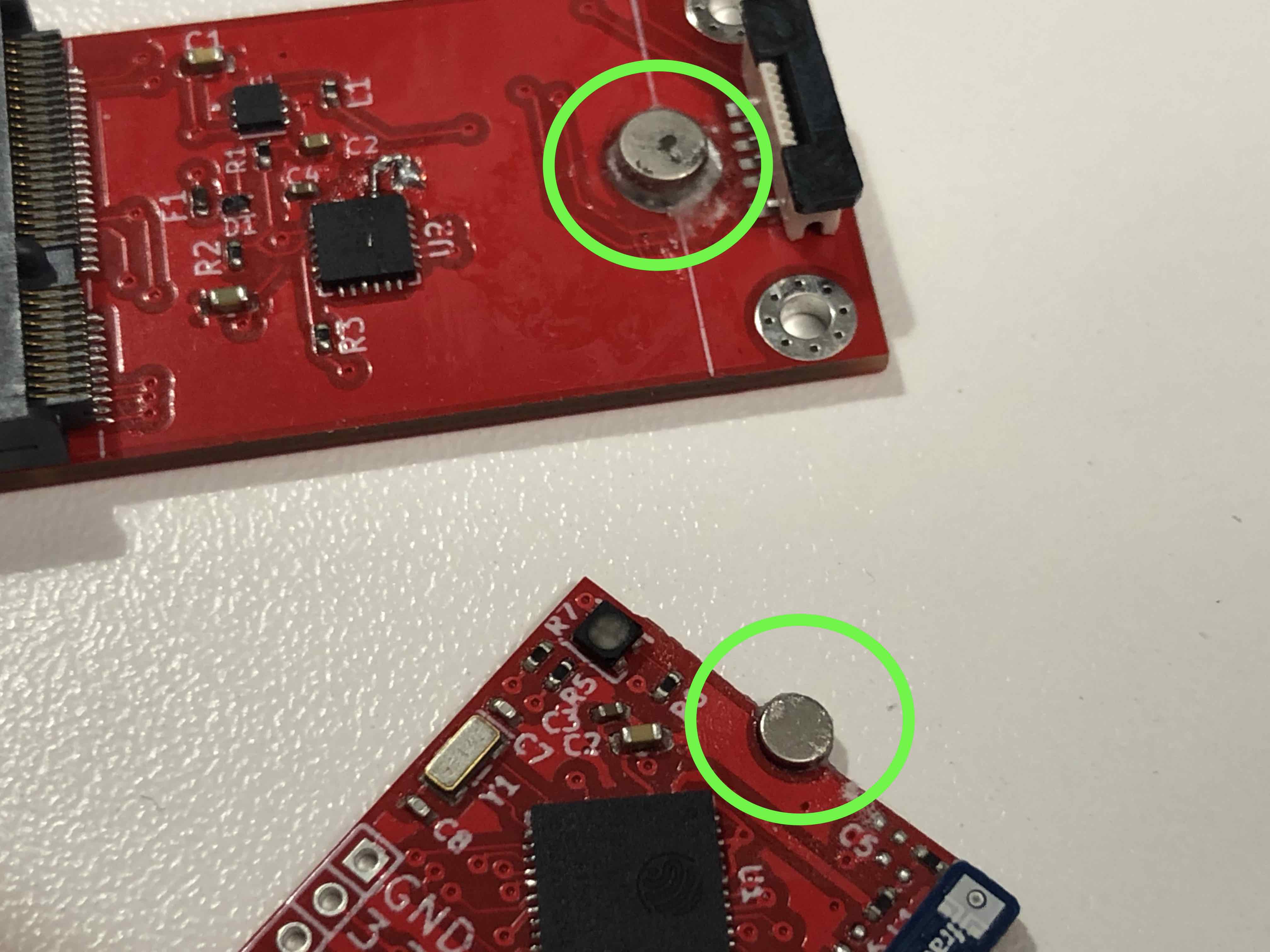
SNAPZZ M.2 magnetic
11/06/2020 at 16:55 • 0 commentsOriginally M.2 modules are screwed down (M2, M2.5) to a standoff soldered to the carrier PCB.
To remove the Module you unscrew the little screw, module pops up and you remove it.
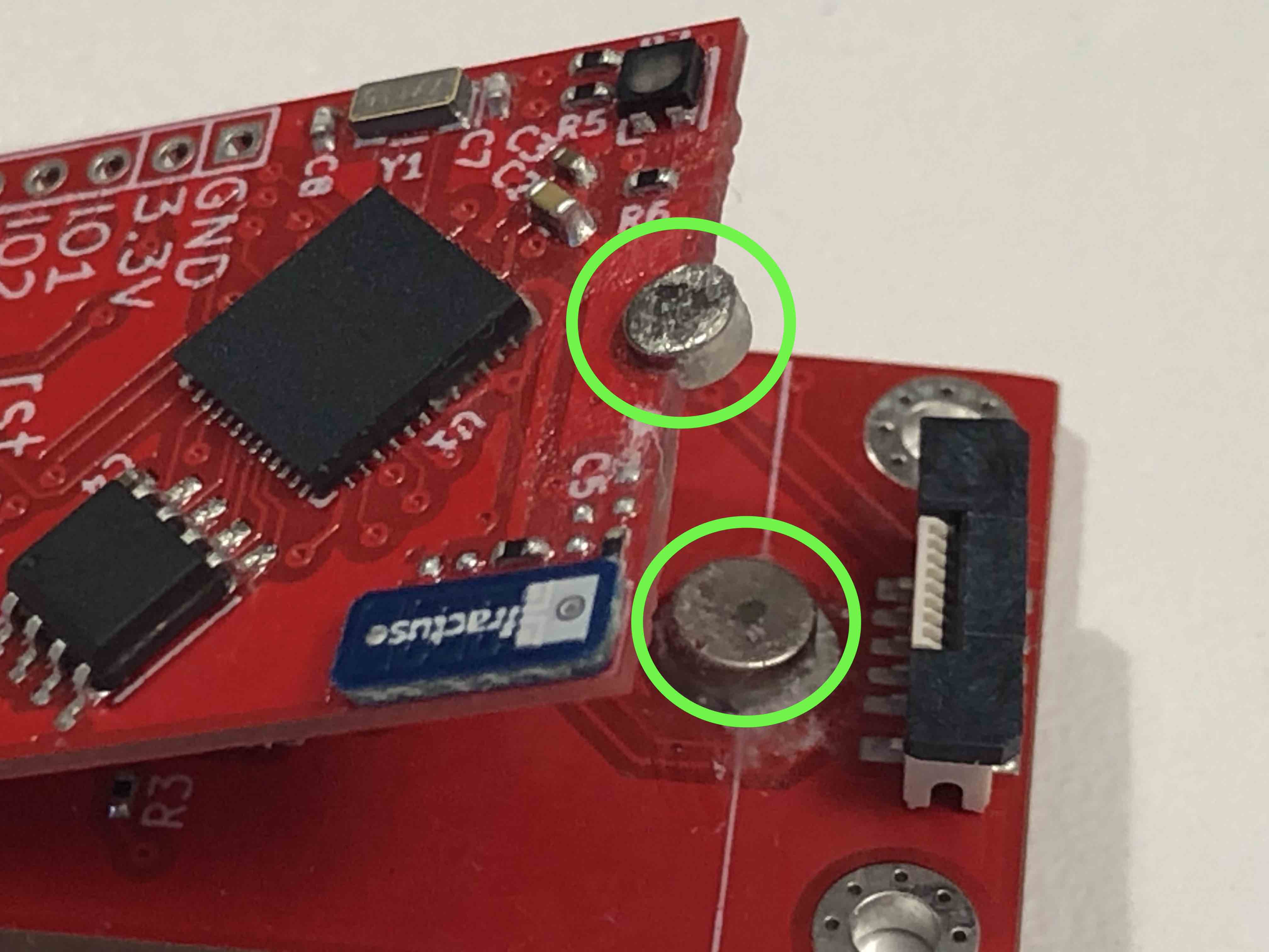
For prototyping this sometimes is annoying so i was experimenting a bit with a magnetic lock. I use a small Neodym magnet and glued it to the carrier PCB. the other Magnet sits in the little recess in the module. Those magnets, yet very small (1.5mm high, 2mm diameter) are surprisingly strong once they make contact.
![]()
![]()
Manufacturability is probably low, as they cannot be soldered. Neodym Magnets have a Curie Temp of ~80 degrees Celsius. Around and beyond this Temperature the Magnets looses it's magnetism permanently.
SNAPZZ - Modular Microprocessor Platform
Modular MCU Platform with decomposed Sections in a M.2 (22/30mm) Formfactor