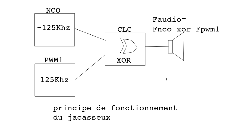
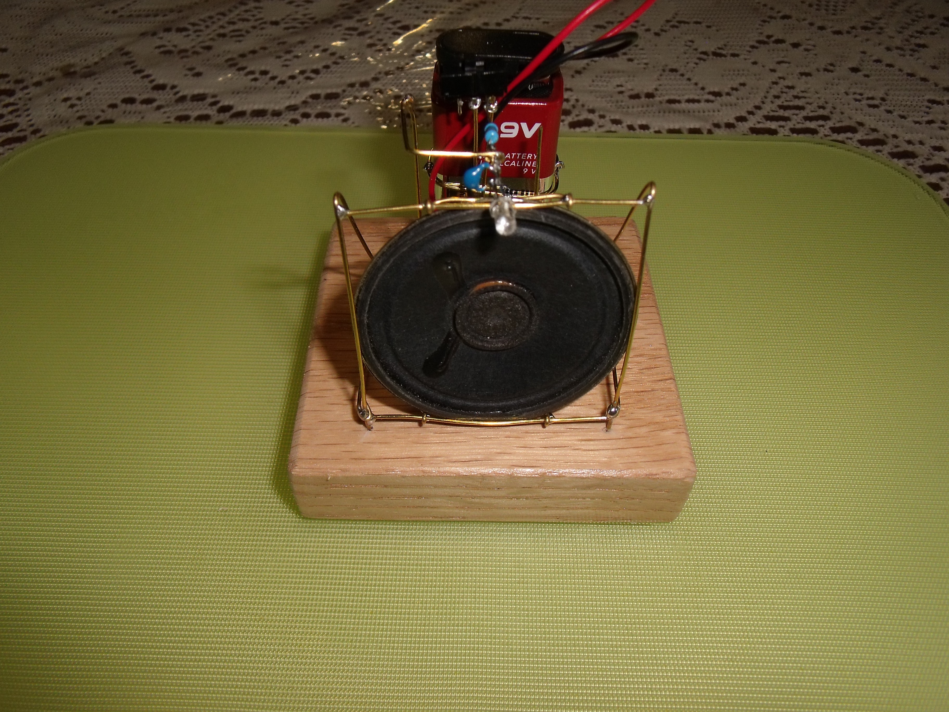
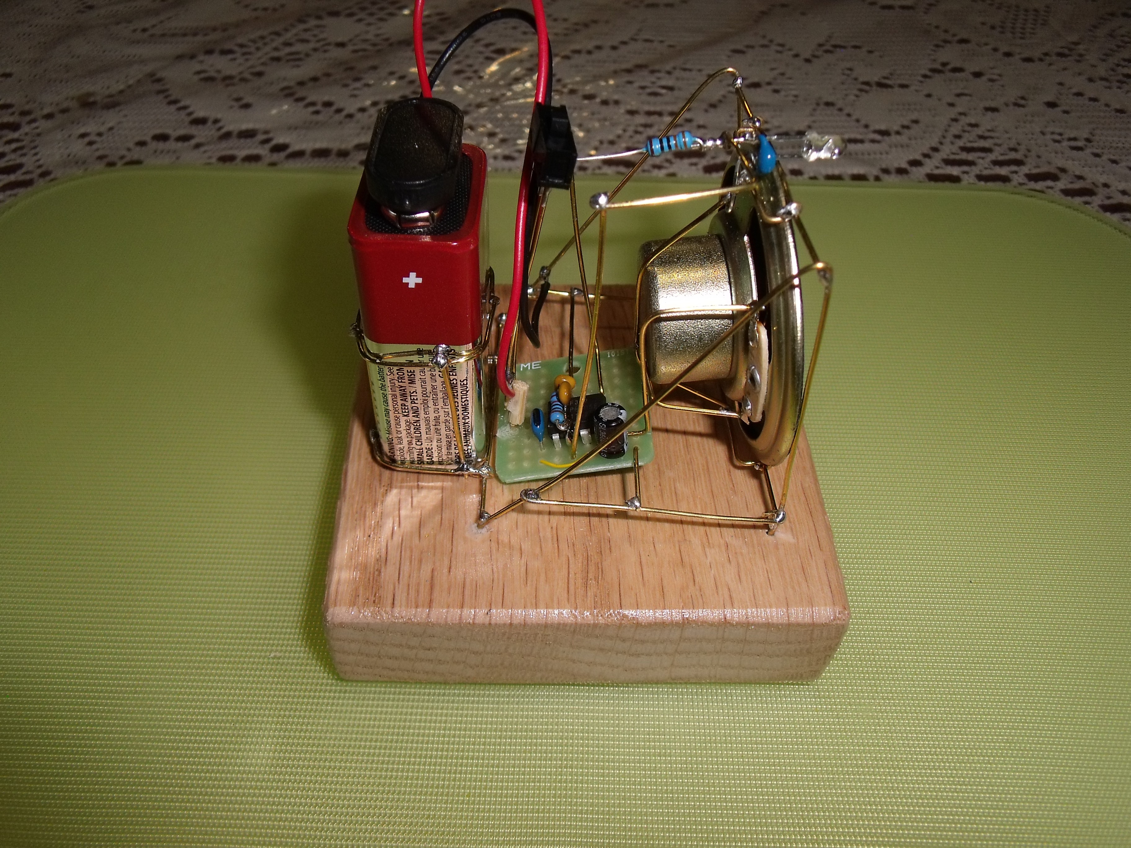
The PIC10F322 has 2 PWM channels, one NCO (numerically controlled oscillator) and a CLC (Configurable Logic Cell). The audio frequencies are not generated directly but by mixing two 125Khz frequency trough XOR gate (part of CLC). When the 2 frequencies are different it result at the output of the XOR gate a continuous variation of duty cycle in a triangular shape. The frequency of this variation is equal to the difference between both frequencies. By keeping this difference in audio range an connecting the CLC output to a speaker one get an audible tone. For this purpose the frequency of PWM channel 1 is set to 125Khz and the same for the NCO. But the NCO frequency is modulated randomly around 125Khz to produce the audio tones. The NCO is modulate instead of PWM because of its higher resolution. the PWM has only 10 bits of resolution while the NCO has a 16 bits increament.
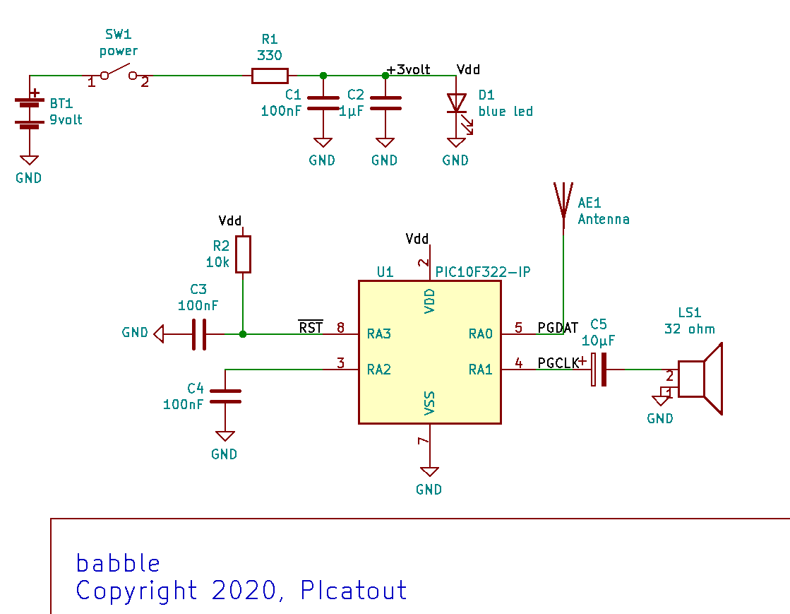
The circuit use a special random generator which consist only of measuring charge time of a capacitor connected to RA2 input. The capacitor charge towar Vdd trough the RA2 pullup. The charge time for the input to switch to 1 is about 1 millisecond but there enough random variation on the TIMER0 counter to use it as random generator.
Most of the time the circuit keep silent. Input RA0 is left floating at high impedance to make it susceptible to electromagnetic noise. Each time this input change state the babble is triggered for 3 seconds.
 Jacques
 Lithium ION
 Jeremy
 MS-BOSS
 Keri Szafir