AdaCore
-
O'PAVES at FOSDEM 2018
01/30/2018 at 12:45 • 0 commentsEvery year, free and open source enthusiasts gather at Brussels (Belgium) for two days of FLOSS-related conferences. FOSDEM organizers setup several “developer rooms”, which are venues that host talks on specific topics.
This year, we will present the O'PAVES project in the Embedded, mobile and automotive room at noon Sunday the 4th of February. https://fosdem.org/2018/schedule/event/open_autonomous_vehicles/
If you happen to be in the area, please come and say hi!
-
The build instructions are on GitHub
11/29/2017 at 11:30 • 0 commentsThe build instructions are now available on GitHub: here. This means you can start making your own O'PAVES car right now!
![]()
-
New version of the hardware (based on the Crazyflie 2.0)
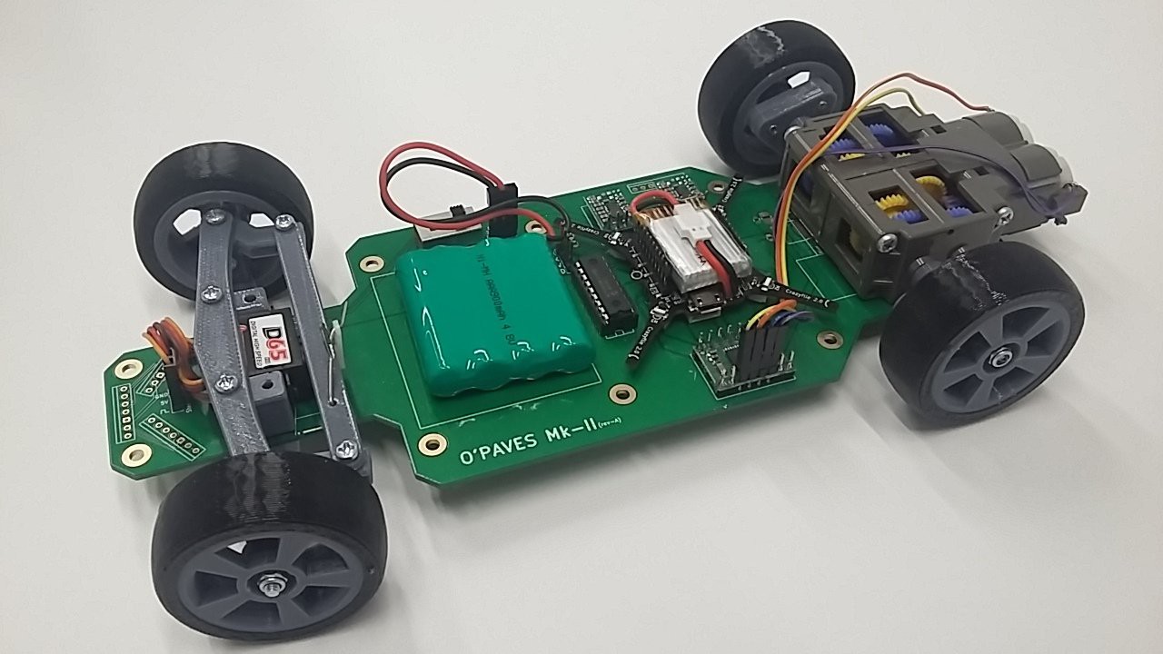
11/16/2017 at 17:11 • 0 commentsInstead of having our own STM32F4 micro-controller circuit, this new design uses the Crazyflie 2.0 nano drone from Bitcraze. The drone is plugged on the O'PAVES board using its extension port. This means that the board is really easy to build (no SMT soldering). Here's a picture of the first iteration of this new design:
![]()
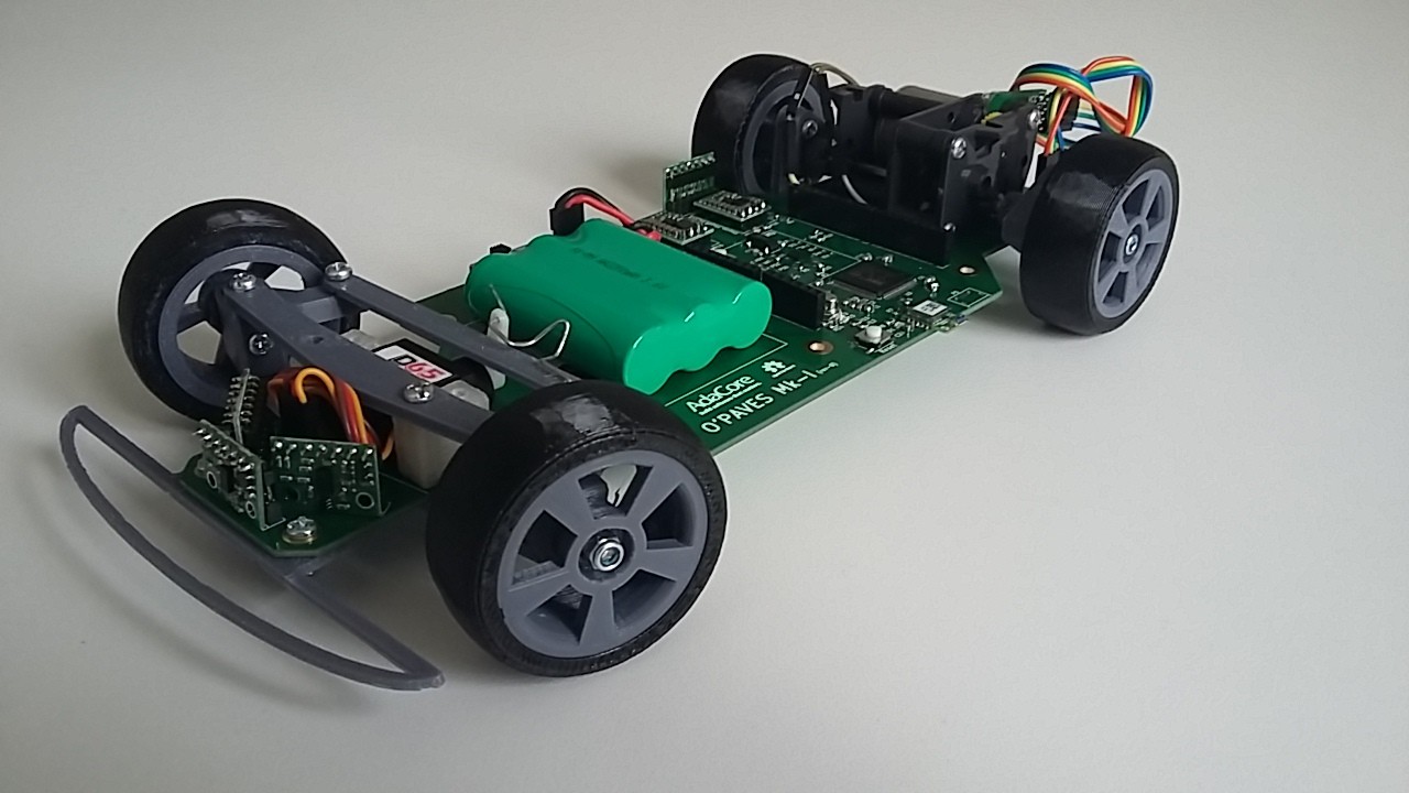
You can also see that the motor is different. The pervious version used a single motor with the two rear wheels fixed on the same shaft. This means the two wheels have to turn at the same speed which results it poor cornering. That's why cars have differential. It's difficult to have a differential on such a small car, it would increase a lot the complexity of the design. For this new version we use a dual motor gear box, which means that each wheel has it's own motor and can turn at a different speed than the other. This improved a lot the cornering as you can see here:
![]()
The dual motor configuration might also allow us to implement active differential, where we can increase the power in one of the two motors to make the car turn tighter.
-
First hardware prototype
07/21/2017 at 13:49 • 0 comments![]()
We just finished the assembly of the first hardware prototype and we would like to take this opportunity to walk you through the design.
The main and most remarkable element is the PCB. Inspired by the Crazyflie flying PCB or the FR4 CNC mill, we are using the circuit board as mechanical and structural element of the design. Not only it holds the electronic circuits, it’s also the frame of the car where the mechanical parts (steering, motor, bumper) are attached.
Some of the advantages of using the PCB as a frame are:
Clean design: We can cleanly route electronic signals to every part of the vehicle without having a mess of wires.
Simple and cheap to manufacture: Nowadays, PCB manufacturing is available to everyone for a relatively cheap price.
The remaining mechanical components are either off the shelf parts (RC servo, DC motor and gearbox) or 3D printed parts in PLA (steering assembly, rims) and NinjaFlex (tires).
For the electronic we have an ARM Cortex-M4F (STM32F405) as the main processing unit, five VL53L0x distance sensor to detect obstacles around the car, an inertial measurement unit (BNO055), a Bluetooth Low Energy module for remote control (RN4871), a DC motor driver (TB6612FNG) and two step-up/step-down converter from Pololu (5V and 3.3V).
Even if the assembly requires some solid soldering skills for the LQFN package of the microcontroller, we think that this design meets the goal of providing a platform that is affordable and easy to reproduce. The total cost of all the components is below 200 euros.
-
Quick status update
06/14/2017 at 16:07 • 0 commentsHere's a quick update on the status of the O'PAVES project.
On the hardware side, the first prototype is 95% a success (see the picture attached). The micro-controller is running fine, the car can move and turn, the different sensors are providing data.
A second version of the electronic board is on the way, with a couple of fixes and the battery moved to the front to put more weight on the front tires and therefore improve cornering.
Of course there are still a ton of problems that might occur when we turn on everything together. Like noise coming from the electric motor that would interfere with sensors signals. But this is a good first step.
On the software side, we've started the development. Here's an overview of the different "modules" of the system:
- Communication
- Talk via Bluetooth with a smartphone app that will allow us to remotely drive the car.
- Talk with an external computer (probably Raspberry Pi mounted on the car) that will provide - eventually - the computer vision and artificial intelligence for autonomous driving.
- System value database and logging
This part will allow to share data between the micro-controller and the external computer and it will also provide logging of the data over time.
- Sensors
We have various sensors on board to know the distance of obstacles around the car, the speed of the wheels, the battery level or the motion of the car (IMU). This part is responsible for acquiring the sensors data and processing it.
- Advanced Driver Assistance Systems (ADAS)
This module will use sensor data to predict a potential collision and provide guidance on how to avoid it. Given the sensors that we have, the avoidance will be limited to emergency braking, i.e. stop the car before crashing into something.
- Control
This module drives the motor and steering according to the pilot's command, or ADAS command in case of the emergency braking.
- Monitor
Watches the system and handles errors or faults report. For instance stopping the car if the connection with the remote control is lost for too long.
The GitHub repository is now public: https://github.com/AdaCore/OPAVES
You will find all the hardware and software sources there.
- Communication
-
The repository is now public
04/14/2017 at 08:42 • 0 commentsJust a quick update to say that the GitHub repository is now public.
https://github.com/AdaCore/OPAVES
-
Demonstrator requirements
12/22/2016 at 15:59 • 0 commentsAutonomous vehicle challenges
O’PAVES aims at providing an open source/open hardware platform for the prototyping and development of autonomous vehicles. For the first step of this project, the goal is not to develop a fully autonomous car, but rather a framework that will open the field to a broader audience by tackling the electronic and real-time control software.
Inspired by the different autonomous vehicle competitions around the world, we identified three main challenges that should be addressable by the platform:
- Lane following
- Obstacle avoidance
- Autonomous parking
During the design of the platform, it will be important to keep those challenges in mind to make sure that we provide the tools (sensors, interfaces, computation power, etc.) that will allow users of O’PAVES to develop algorithms addressing them. However, we do not plan to actually implement lane following and obstacle avoidance as part of this one year project, the time frame being too short.
Active Safety Subsystems
To use the car to its maximum performance while keeping it in a safe state, the O’PAVES platform will provide three active safety subsystems operating between the driver and the car.
These systems will make sure to keep the car in a safe and controlled state, potentially by overriding the driver's commands. The driver could be a human operator or an artificial intelligence, both will benefit from this extra safety and control.
Anti-lock Braking System
During an emergency braking, the force applied to the brake discs might be so strong that the wheels stop turning while the car is still in movement. The wheels then skid on the road surface, reducing control of the vehicle while increasing braking distance. The Anti-lock Braking System (ABS) will override the driver's command and lower the braking force until the wheels regain traction. This is now a common and unavoidable safety feature of modern cars, it’s even mandatory for all passenger car sold in the European union since 2004.
Requirements for the O’PAVES platform:
To implement ABS in our platform, we have to be able to control the braking force applied to the wheels and measure the rotation speed to detect a blockage.
Traction Control System
While ABS avoids loss of traction during braking, Traction Control System (TCF) does the same during acceleration. This allows for maximum performance while keeping fine control of the vehicle’s trajectory.
Requirements for the O’PAVES platform:
To implement TCS in our platform, we have to be able to control the acceleration force applied to the wheels and measure the rotation speed of the wheels.
Emergency braking
Emergency braking is a safety system detects an imminent collision and automatically brakes to avoid the collision. The detection is done by measuring relative distance from the car a surrounding objects.
Requirements for the O’PAVES platform:
To implement the emergency braking system in our platform, we have to be able to know the distance of obstacles to the front and rear of the car.
Hardware requirements
Frame
For the O'PAVES project we want to develop a platform that is as close as possible to a consumer car to demonstrate the relevance of the tools and technology that we are going to use. On the other hand we want to keep the cost low and the platform easy to reproduce/make.
To satisfy those two very different constraints, we will use a scale model car (1/10th, 1/12th or 1/18th) with rear-wheel drive and two front steering wheels. Whether we will use an off-the-shelf remote controlled car or use 3D printed parts is to be determined during the hardware development phase.
Drivetrain and encoders
Direct drive, no differentialIn order to make the base platform easy to create, we chose to keep the drivetrain simple, and thus use a direct drive with no differential. This direct drive with no differential is a simple component that is composed on an axis (on which the rear wheels are fixed) and either a central motor or a gearing mechanism allowing the motor to rotate the axis.
MotorTwo options are possible here: either brush or brushless DC motors.
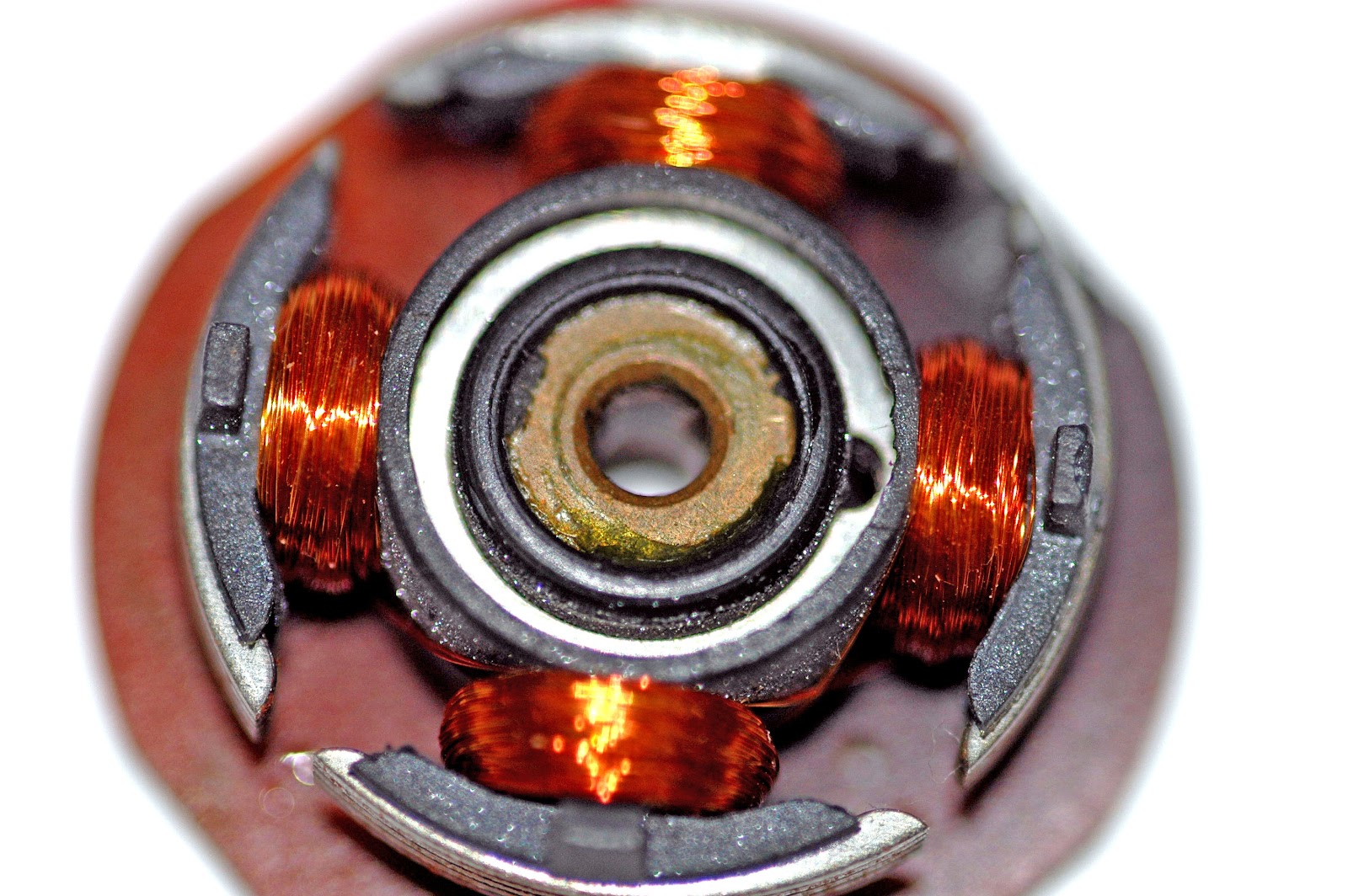
Brush motorsDC brush motors are one of the simplest types of motors. A typical brush dc motor consists of an armature (a.k.a., rotor), a commutator, brushes, an axle, and a field magnet.
The brushes charge the commutator inversely in polarity to the permanent magnet, in turn causing the armature to rotate. The rotation’s direction, clockwise and/or counterclockwise, can be reversed easily by reversing the polarity of the brushes, i.e., reversing the leads on the battery.
Brushless motorsA typical brushless motor has permanent magnets which rotate around a fixed armature, eliminating problems associated with connecting current to the moving armature. An electronic controller replaces the brush/commutator assembly of the brushed DC motor, which continually switches the phase to the windings to keep the motor turning. The controller (ESC: Electronic Speed Controller) performs similar timed power distribution by using a solid-state circuit rather than the brush/commutator system.
In our context, using ESC and brushless motors look more appealing, in particular because the controller knows the speed of the motor by using the hall sensor. We could use this information for various features: position calculation, anti-lock braking system, etc.
The ESC need to allow retrieving this information, very few models commonly used in R/C propose a proper output.
An alternative would be to attach a coding wheel to the drivetrain.
Sensors
Inertial Measurement Unit (IMU)An IMU is a integrated sub-system that measures linear and angular motion usually with multiple internal sensors (accelerometers, gyroscopes, magnetometers). With the development of Micro-Electro-Mechanical-System (MEMS) sensors, IMUs are getting smaller and cheaper.
Proximity/RangeTo achieve the challenges of autonomous parking, obstacle avoidance and emergency braking, the platform needs to know the distance of potential objects around the car.
This task is best achieved with proximity sensors that deliver a distance measurement. The platform will need, at least, one proximity sensor to the front, one to the back and one to the right for autonomous parking.
There are different types of proximity sensors (infrared, ultra-sound, laser time-of-flight). They all offer different performance, price, and integration options. The type, number, and location of sensors will be selected as part of the hardware platform definition task (WP2).
Processing
Regarding processing, we want to use an easily extendible microcontroller that provides sufficient computation power and, ideally, that is well-known from the public.
Most of the ARM Cortex-M based microcontrollers meet these high-level requirements.
Moreover, AdaCore has already done a project that was based on this kind of microcontrollers with the Crazyflie. The project consisted into reimplementing the original firmware of the Crazyflie, a tiny customizable drone platform based on a STM32F4 microcontroller, using Ada and SPARK. This project presents many similarities with O’PAVES regarding high-level requirements (open source platform, easily reproducible and customizable), hardware requirements (sensors, frame, actuators...), and software requirements (main loop fetching commands and sensor values to compute the required values for the actuators).
We made several measurements based on the reimplemented Crazyflie firmware to have a better idea of our requirements in terms of CPU and memory usage.
Regarding CPU usage, we measured the time spent by the firmware’s main loop using a logic analyzer branched on a Crazyflie GPIO that is set to HIGH (3.3V) ) when entering the loop and cleared to LOW (0.0V) when leaving it. This main loop task is called every 2 ms and our measurements indicated that it was spending approximatively 1ms to execute (when compiled with debug flags).
Example of CPU usage measurement using Saleae Logic
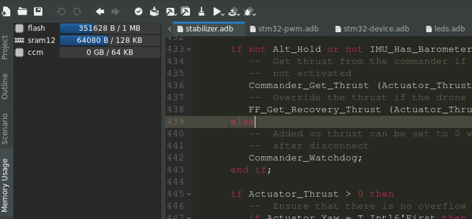
For the memory usage, we combined two different static analysis approaches: the ld linker --print-memory-usage switch that outputs the statically computed memory usage for each defined memory region; an AdaCore tool called GNATstack which can predict the maximum size of the memory stack required to host an embedded software application.
GNAT Programming Studio screenshot of the Memory Usage view for the Crazyflie firmware
By combining these two different approaches, we were able to measure the memory usage of both ROM (≈ 34%) and RAM (≈ 54%).
CPU and memory usage measurements made on the re-implemented Crazyflie firmware showed us that a similar microcontroller should perfectly fit the needs of the O'PAVES project.
Communication
A communication link is needed to remotely control the car: general direction, urgent stop, manual control… The main requirements are price, bandwidth, range, availability.
The well-known wireless links fit all the bill:
Protocol
Freq
Bandwidth
Range
Power
Modules
Bluetooth
2.4Ghz
800 Kpbs
<30m
low
~10E, UART
BLE
2.4Ghz
270 Kpbs
50m
low
~10E, UART or SPI
ZigBee
2.4 Ghz, 868Mhz
250Kpbs
10m
low
~20E, UART
Wifi
2.4, 3.6, 5 Ghz
11 Mbps
30m
high
20E, UART
High bandwidth technology like Wifi could be interesting to transmit video, but in that case would be less simple to use. All these technologies are available as integrated modules using UART or SPI interface. The main advantage of these modules is the ease of use (no need to know HF rules for PCB) and therefore the possibility to test several of them.
We will start with Bluetooth as it is also available on laptops and cell phones.
It might be interesting to also test a less common technology like Z-Wave, also available as a UART module. It uses different frequencies (868 Mhz) and therefore reduces interference risks.
Test and validation
ISO26262 is an international standard for functional safety of electronic and software systems in passenger cars. It defines requirements for software development, specifically regarding design and implementation, unit testing, integration testing or verification of software safety requirements.
One goal of the O'PAVES project is to use in an automotive context those technologies that have proved successful in high-assurance application areas such as aerospace and rail. To demonstrate relevance of those technologies we are going to apply them to some of the requirements and mechanisms listed in ISO26262. In particular:
- Unit testing
- Test coverage (MC/DC)
- Formal notation for unit design
- Formal verification
- Static code analysis
- Upper estimation of required resources
- Compliance of the source code with the coding guidelines
We do not plan to apply all requirements to the entire software, but to demonstrate tools and techniques on specific units. Deciding which tools and techniques to use on which part of the software will be part of work packages 5 (Software development) and 6 (Test and validation).