 Jelto
JeltoThe clock consists of:
- Arduino Nano
- Arduino Breakout Shield with terminals
- DS3231 real-time-clock
- 6x WS2821 RGB leds
- 4x Numitron tubes IV-9
- 4x Shift registers 4049N
- Old 1HE server power supply

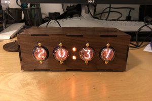
A post apocalyptic Numitron clock based on Arduino Nano and DS3231
Already have an account? Log in.
To make the experience fit your profile, pick a username and tell us what interests you.
The clock consists of:
To keep the design simple I decided to adjust the time only with a serial command.
Most of the logic comes from the DS3231_set example code.
The Arduino listens on the serial connection with 9600 baud.
It accepts the following string:
YYMMDDwHHMMSSx
YY= two digit year (example '20')
MM=two digit month (example '10')
DD=two digit day (example '26')
w=separator
HH=two digit hour (exampel '19')
MM=two digit minute (example '10')
SS=two digit second (example '20')
x=sparator at the end
Full example would be:
201026w191020x
for the 26th of October 2020, 19:10:20
To set the date with a Linux computer just type:
stty -F /dev/ttyUSB0 -hupcl
echo -n "201026w191020x" > /dev/ttyUSB0
The case consists of a empty 1HE server power supply. To make it a bit more interesting I added some handles, mesh and elements I scraped from an old case I found on the flea market.
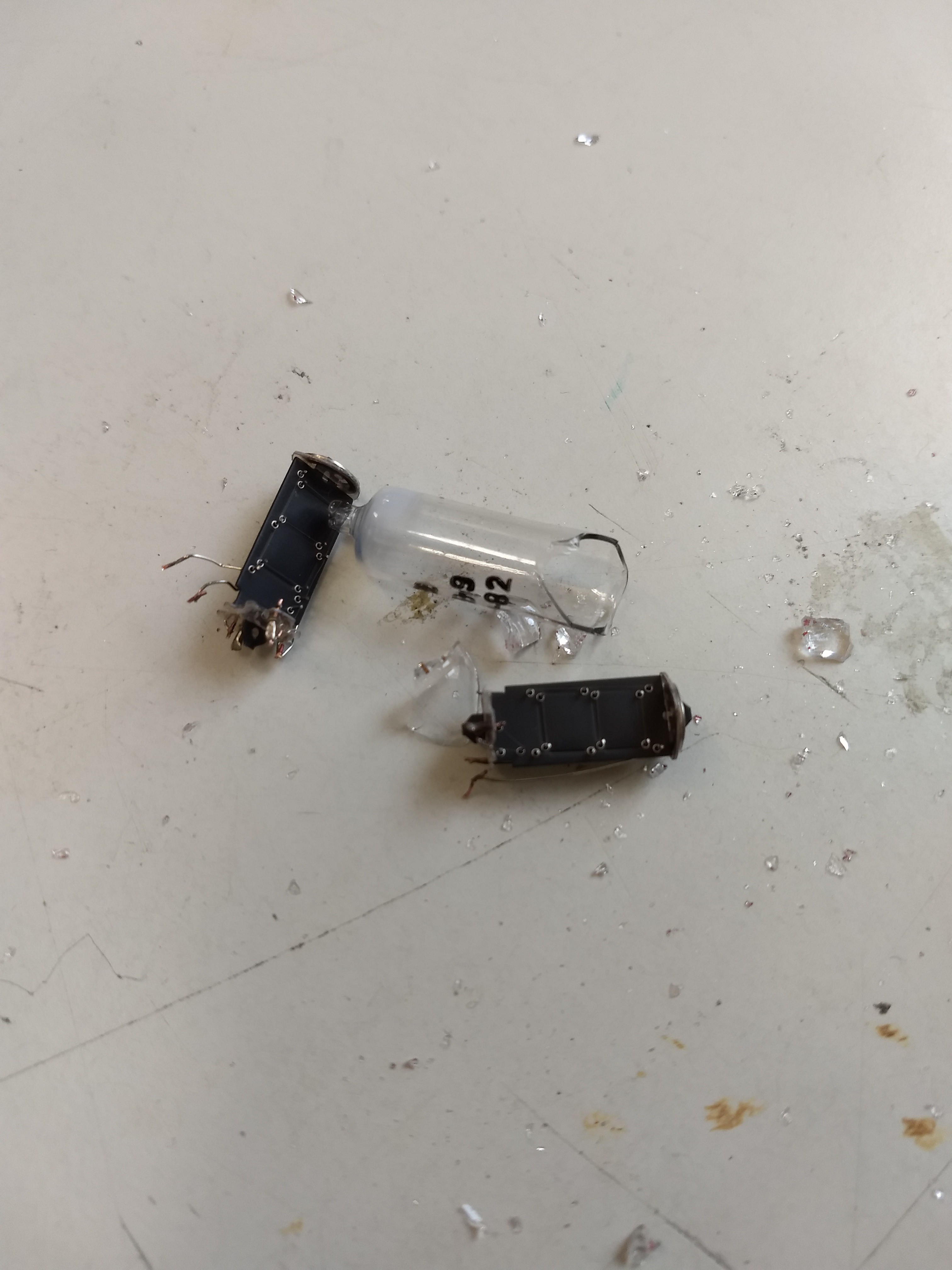
By assembling the case of the clock I managed to break two of the tubes. The case was quite tight and caused some pressure on the glass tubes. Luckily I had two spare tubes so I replaced them and added more space in the case.
However unsoldering the broken glass tubes was quite stressful.
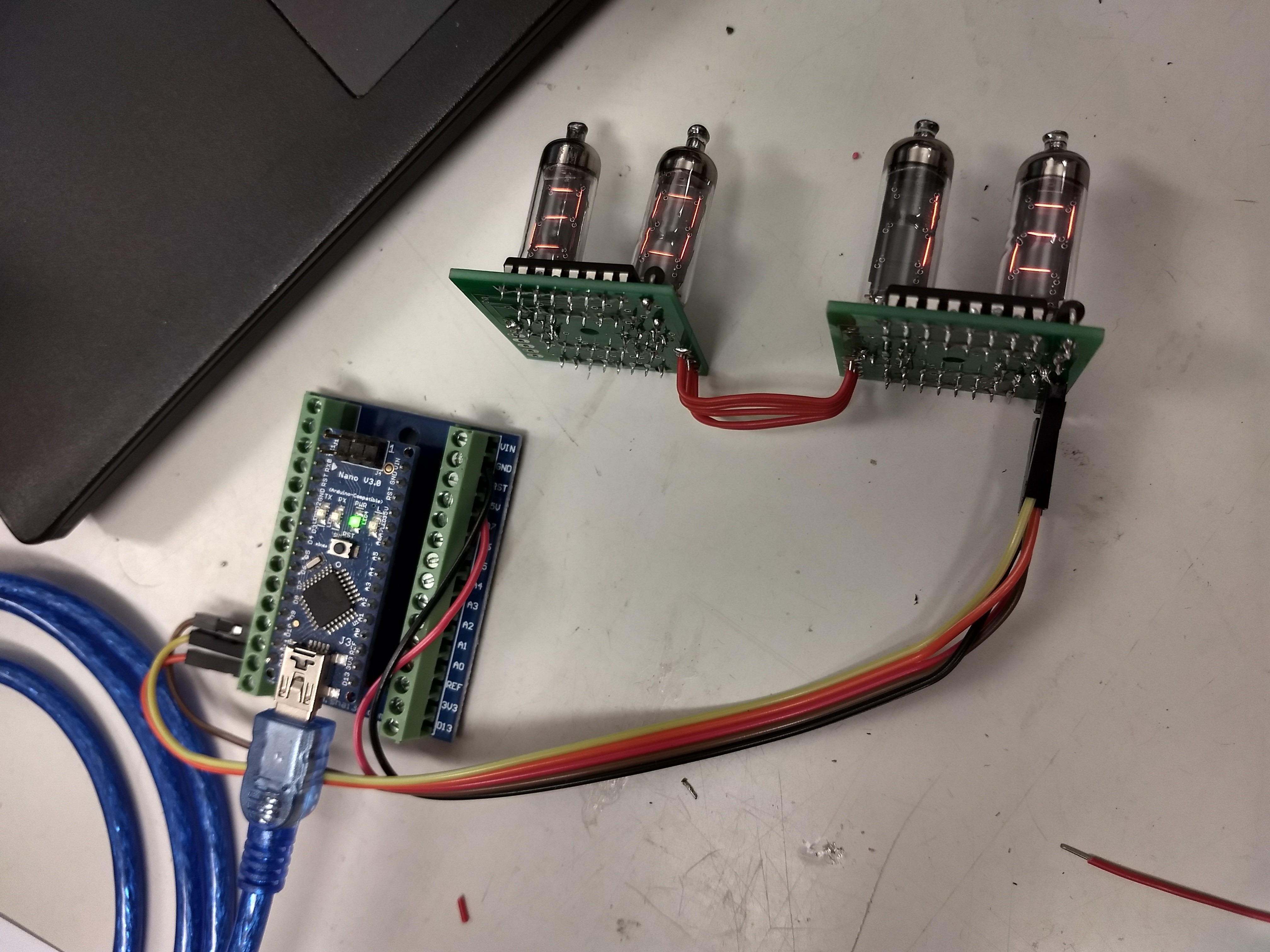
The next step was to solder the next pair of Numitrons to the PCB.
Due to the usage of simple shift registers, the PCBs can be chained together.
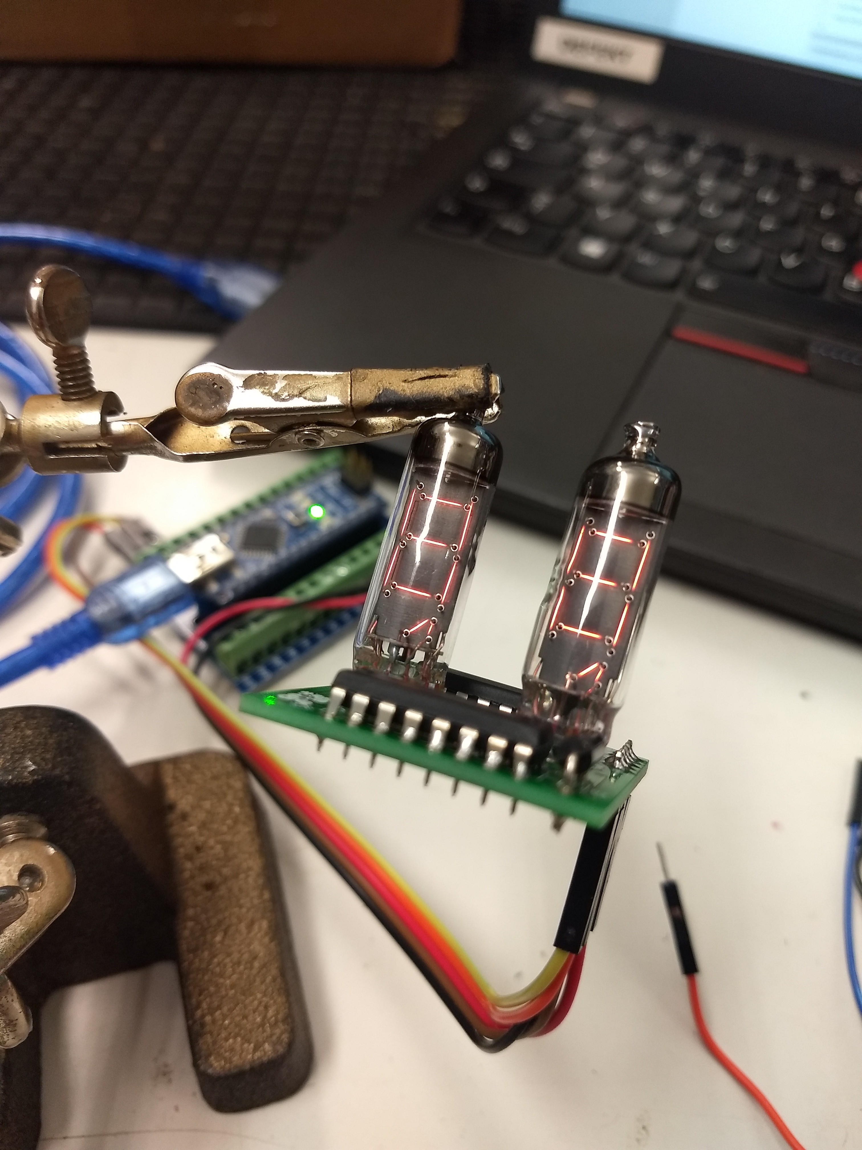
The first step was to solder the Numitron tubes to the pcbs. The PCBs are quite simple and just consist of a pair of shift registers, two tubes and a diode. I found the pcb here.
After soldering the tubes I connected the Arduino and created the mapping for each number. The mapping can be found in the linked Github repository. The idea is to map the right bitmapping to each number for one tube:
byte digit[10]= {B00100001, B11111001, B00010101, B10010001, B11001001, B10000011, B00000011, B11110001, B00000001, B11000001};

 Pierre Cauchois
 Giulio Pons
 ElectroBoy
 Chris B