Bud Bennett
-
Final Product
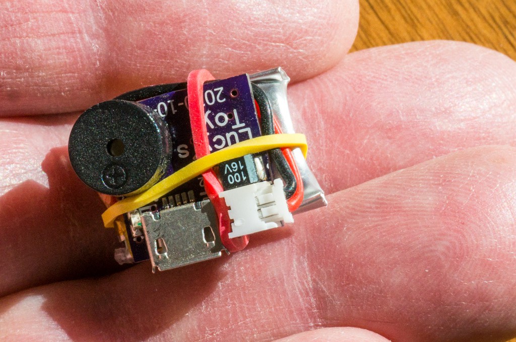
12/07/2020 at 00:54 • 0 commentsThe toy is essentially done, and working properly. I encased it into a baltic birch enclosure, with lots of hot glue and CA glue.
![]()
The openings are for the buzzer and the micro-USB charger. I was surprised that it was nearly too large to fit inside the opening in her new toy -- a Kong Comfort Kiddos Bear:
![]()
Lucy is always enthralled with any new toy. This one is no different. I think it will remain #1 for a while.
![]()
At this point I think the project is completed. Good enough. I'll post the gerber files and the MPLABX project in the files section.
-
PIC programming modifications
12/04/2020 at 01:02 • 0 commentsI made a mistake programming the LIS3DH accelerometer. The INT1 duration register was not addressed properly, so the accelerometer would not delay the interrupt output when detecting a free-fall event. I discovered the error and made changes to the PIC code to change the free-fall duration to 320ms, along with increasing the free-fall threshold to 320mg (from about 100mg).
Results:
- Previously, when Lucy dropped her toy from a few inches off the floor the toy would beep. Now, the toy does not beep until it is dropped about 3 feet in height. It also does not beep when she shakes it or a human shakes it.
- You still must be careful tossing the toy so that is doesn't rotate (revolve?) or the accelerometer won't generate an interrupt. Lucy has a lot of trouble locating the toy now if it doesn't beep.
The PIC code is very close to complete. My wife thinks it should be able to discriminate between a rotating toy and a non-rotating toy, but perfection is hard to achieve and I'm satisfied with the performance so far.
-
First Pass Prototypes
11/13/2020 at 16:11 • 0 commentsThe PCBs arrived a couple days ago. I had a lot of trouble getting the accelerometer soldered properly. The technique that worked on the accelerometer was to create small solder bumps both on the PCB and the LIS3DH, use a good amount of flux paste, and solder it to the PCB before other components were mounted. This allowed me to test the connections using a diode checking function on the DVM to make sure that all the traces going to the PIC were properly soldered. Without this check there was a high probability that at least one connection (usually the INT1 pin) was open.
I did not populate the 1N4148 diode. The LIS3DH operates just fine with a 4.2V supply. I should have implemented an option for a shorting resistor across the diode, but just put a short solid wire across it instead.
With a working PCB, I measured the following:
Supply Current at idle = 12.2µA
Charging current = 75mA (including the LED current)
This idle current is pretty close to that expected for the system using the following conditions:
- The PIC idle current is around 0.7µA during sleep with the watchdog timer running.
- The LIS3DH is running at 25Hz and expected to consume 6uA @ VDD = 3.3V. But the current nearly doubles when VDD is increased to 4.2V.
- The battery charger IC contributes less than a few hundred nA of leakage current drain on the battery.
I was expecting to have the LIS3DH run at 10Hz and draw only 4µA, but increased the ODR to 25Hz and the duration of the interrupt event to 400ms to lessen the chance of a false free fall detection. Even so, with 12µA idle current I expect the 120mAh battery to last about 1 year between recharges, depending upon how often it is tossed.
![]()
It's a pretty small package -- even with the battery attached. The battery is contained temporarily with a couple of small rubber bands. Hot glue will probably be the permanent attachment method. I've tossed it a few times. It doesn't always trigger the beeper. The package is so small by itself that the unit tends to revolve in flight and might not drop below the free fall threshold. There have been quite a few false triggers as well. I'm hesitant about removing the PIC and reprogramming it with different parameters for the accelerometer. Every time I have desoldered the PIC I have been unable to reprogram it -- no idea why at this point. Perhaps the better approach would have been to use a DIP with a socket for experimentation and then switch to an SOIC after getting the parameters right.
The first testing of the unit in one of Lucy's existing plush toys did not go well. Lucy regarded the beeper as a violation of one of her favorite toys and wanted nothing to do with it. I ordered a different plush toy, with a velcro pouch to hold the beeper. Hopefully, Lucy will respond better to a new toy with the beeper installed. I'll add a new log with those results when the new toy arrives.
-
The Code
10/27/2020 at 20:22 • 0 commentsThe PIC program is written in assembler. It is pretty straightforward and can be explained in three flow charts.
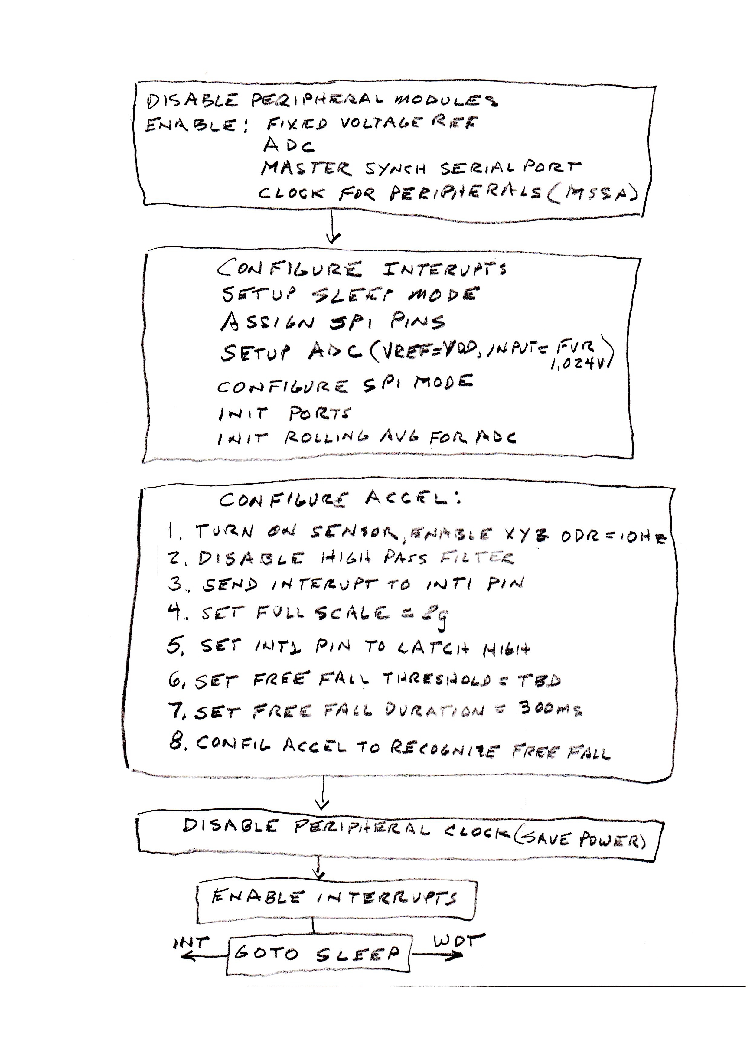
![]() The chart above shows the steps necessary to configure the PIC and the accelerometer. Most of the peripheral modules are disabled. The only modules needed are the FVR, ADC, and MSSP (for the SPI interface). Then the modules are configured. The watchdog timer (WDT) is set to overflow after 264 seconds. The ADC is set to run on its own RC clock and place the 10-bit result so that the 8LSbs occupy the low byte of the two byte ADC result register. The SPI is set to match the protocol required by the accelerometer and is set to master mode since it controls the SPI clock (SCK). The I/O ports are set to digital with required input/output assignment. Lastly, the 8-byte ADC rolling average is zeroed out as a precaution.
The chart above shows the steps necessary to configure the PIC and the accelerometer. Most of the peripheral modules are disabled. The only modules needed are the FVR, ADC, and MSSP (for the SPI interface). Then the modules are configured. The watchdog timer (WDT) is set to overflow after 264 seconds. The ADC is set to run on its own RC clock and place the 10-bit result so that the 8LSbs occupy the low byte of the two byte ADC result register. The SPI is set to match the protocol required by the accelerometer and is set to master mode since it controls the SPI clock (SCK). The I/O ports are set to digital with required input/output assignment. Lastly, the 8-byte ADC rolling average is zeroed out as a precaution.The accelerometer is configured via the SPI interface to set an interrupt pin, INT1, when a free-fall event is detected. This sequence is right out of the application note for the LIS3DH, with a few parameters modified for this purpose. The peripheral clock is disabled to save power since it is only needed for the SPI interface.
The interrupts are enabled and the PIC goes to sleep, consuming only a fraction of 1µA. There are two ways to wake it from sleep: a WDT overflow every 264 seconds, or a interrupt on INT.
![]() When the external INT pin is asserted the above routine wakes the PIC from sleep and executes. The beeper is exited in a series of 20 beeps (50ms on, 50ms off) for 2 seconds. Then there will be a 2 second pause and a 100ms beep, which repeats TBD times. After that the SPI is used to read data from the accelerometer to clear the interrupt event and unlatch the INT1 pin. PIC peripheral clocks are again disabled, the PIC interrupt flag is cleared and general interrupts are enabled. The routine returns to the running program -- most likely back to sleep.
When the external INT pin is asserted the above routine wakes the PIC from sleep and executes. The beeper is exited in a series of 20 beeps (50ms on, 50ms off) for 2 seconds. Then there will be a 2 second pause and a 100ms beep, which repeats TBD times. After that the SPI is used to read data from the accelerometer to clear the interrupt event and unlatch the INT1 pin. PIC peripheral clocks are again disabled, the PIC interrupt flag is cleared and general interrupts are enabled. The routine returns to the running program -- most likely back to sleep.![]() The WDT wakes up the PIC every 264 seconds. This routine counts out 24 hours before it checks the battery voltage. If the battery voltage is above 3.3V then the 24 hour timer is reset and the cycle begins again. If the battery voltage is below 3.3V then the PIC will beep 5 times (so as not to get it confused with a smoke detector) and go back to sleep until the WDT wakes it again to repeat the battery voltage check. I'm hoping that it won't do this at 2:00am.
The WDT wakes up the PIC every 264 seconds. This routine counts out 24 hours before it checks the battery voltage. If the battery voltage is above 3.3V then the 24 hour timer is reset and the cycle begins again. If the battery voltage is below 3.3V then the PIC will beep 5 times (so as not to get it confused with a smoke detector) and go back to sleep until the WDT wakes it again to repeat the battery voltage check. I'm hoping that it won't do this at 2:00am.I will post the entire MPLABX project to the files section when it is solidified.
-
Breadboarding
10/26/2020 at 19:56 • 0 commentsNormally, I would use a simulator to verify the correctness of the design, but Microchip's simulator for the PIC16F18313, that runs under its MPLABX IDE, doesn't implement the Master Synchronous Serial Port peripheral. I have a PicKit4 programmer/debugger (not a clone). I thought that it would be easier to work with DIP parts than SOICs using a ZIF socket, so I purchased 4 PIC16F18313 DIPs from Digikey.
The PicKit4 blew up the first 3 parts that I tried to program. All the program was supposed to do was toggle an output pin at a 1 second rate after configuring all of the peripherals. This was a problem that I was familiar with -- my previous work-around was to use low voltage programming. But all of the pins on this chip were being used as I/O and LVP was not allowed if the MCLRE config bit was not set.
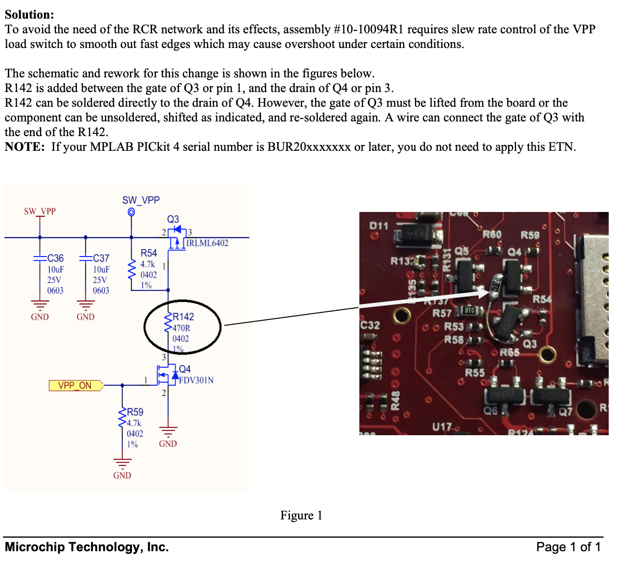
I finally trolled the internet to see if others were having this problem and found this YouTube video. The guy that posted the video said that Microchip had posted a technical note for a fix to the PicKit4 on it website -- ETN #37 MPLAB® PICkit 4 VPP Overshoot Modification. I was going to implement the suggested mod, but something was fishy between the provided schematic and the photo of the mod on the PCB:
![]()
The schematic seems OK to me, but the image shows that they disconnected the gate of Q3 from R54 and connected R142. This doesn't match the schematic. It seemed to me that they could not have properly tested the fix if the implementation was incorrect. I contacted Microchip, told them about the ETN issue and the YouTube video, and asked them to send a replacement for my PicKit4 (serial #BUR18XXXXX). In the meantime I implemented the 120Ω resistor at the VPP pin of my old PicKit4, which was recommended by the guy in the YouTube video. While this purported fix allowed me to program the PIC with the correct function, the current drain after programming increased from an expected 20µA to between 16mA and 60mA. Something still wasn't right and now all of my PIC16F18313 DIPs were gone. I had a PIC16F18323, which is just a 313 with 14 pins. When the new PicKit4 arrived I was able to program the 14pin DIP without damaging it. It's the only DIP part that I have left.
Microchip requested that I send the defective PicKit4 back to them at my expense...FAT CHANCE!
The Breadboard:
The LIS3DH accelerometer is mounted on an Adafruit breakout board. The passives are just bypass caps and a current limit resistor for the LED, which substitutes for the buzzer.
![]()
I hot glued a 15400 battery holder for the li-Ion power source allow the entire unit to be tossed for testing. At this point I have enough code working to configure the LIS3DH to detect a free-fall event lasting 400ms and assert an interrupt to the PIC. The PIC then activates the buzzer in this pattern: 20 50ms bursts lasting 2 seconds, then a 100ms burst every 2 seconds over the remaining 10 seconds. Then the PIC goes back to sleep until interrupted by the accelerometer and the cycle repeats. The buzzer pattern may change after observing Lucy's pursuit timeline with her chiming ball.
Next step is to add a battery monitor to announce when the battery requires recharge.


 The chart above shows the steps necessary to configure the PIC and the accelerometer. Most of the peripheral modules are disabled. The only modules needed are the FVR, ADC, and MSSP (for the SPI interface). Then the modules are configured. The watchdog timer (WDT) is set to overflow after 264 seconds. The ADC is set to run on its own RC clock and place the 10-bit result so that the 8LSbs occupy the low byte of the two byte ADC result register. The SPI is set to match the protocol required by the accelerometer and is set to master mode since it controls the SPI clock (SCK). The I/O ports are set to digital with required input/output assignment. Lastly, the 8-byte ADC rolling average is zeroed out as a precaution.
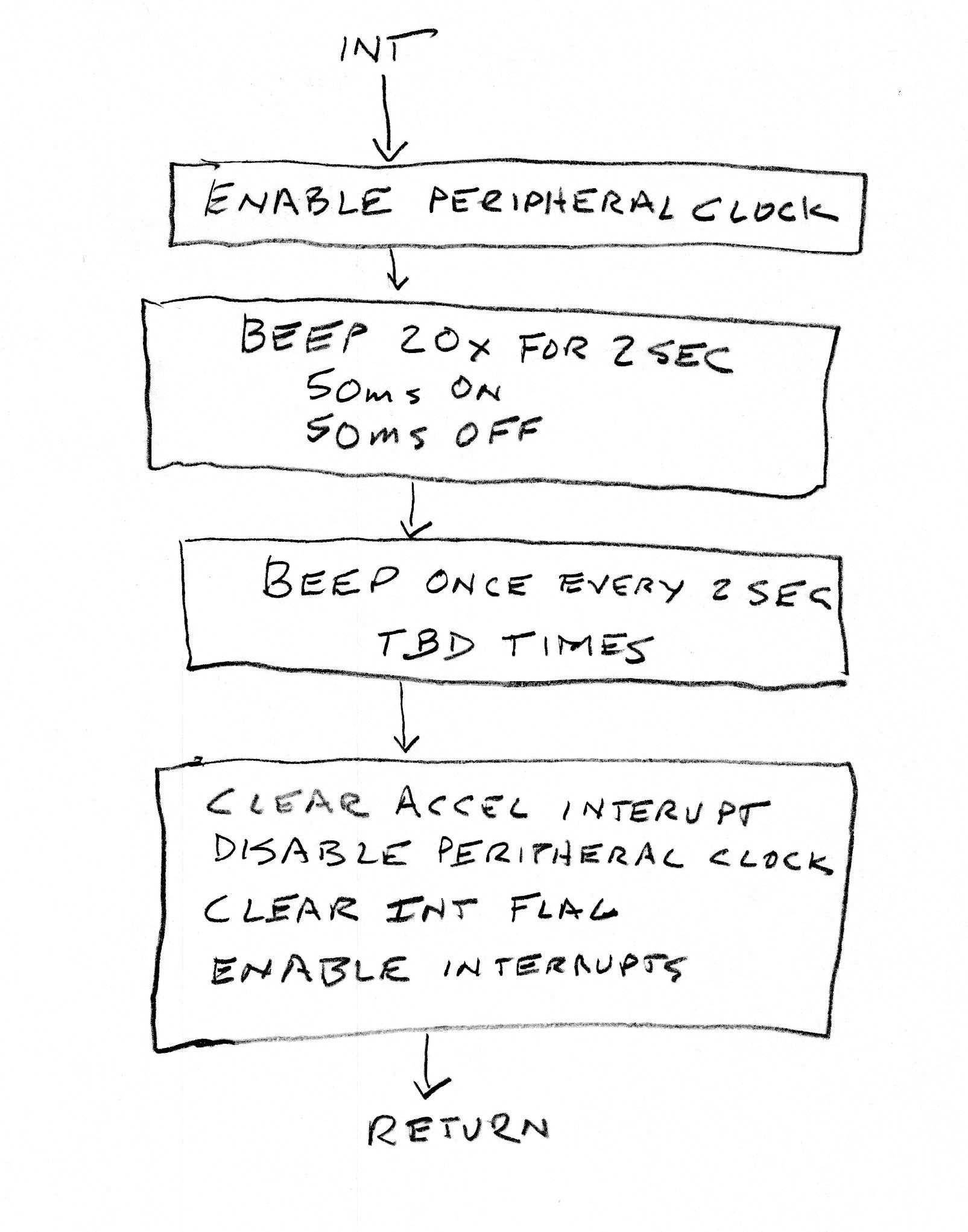 When the external INT pin is asserted the above routine wakes the PIC from sleep and executes. The beeper is exited in a series of 20 beeps (50ms on, 50ms off) for 2 seconds. Then there will be a 2 second pause and a 100ms beep, which repeats TBD times. After that the SPI is used to read data from the accelerometer to clear the interrupt event and unlatch the INT1 pin. PIC peripheral clocks are again disabled, the PIC interrupt flag is cleared and general interrupts are enabled. The routine returns to the running program -- most likely back to sleep.
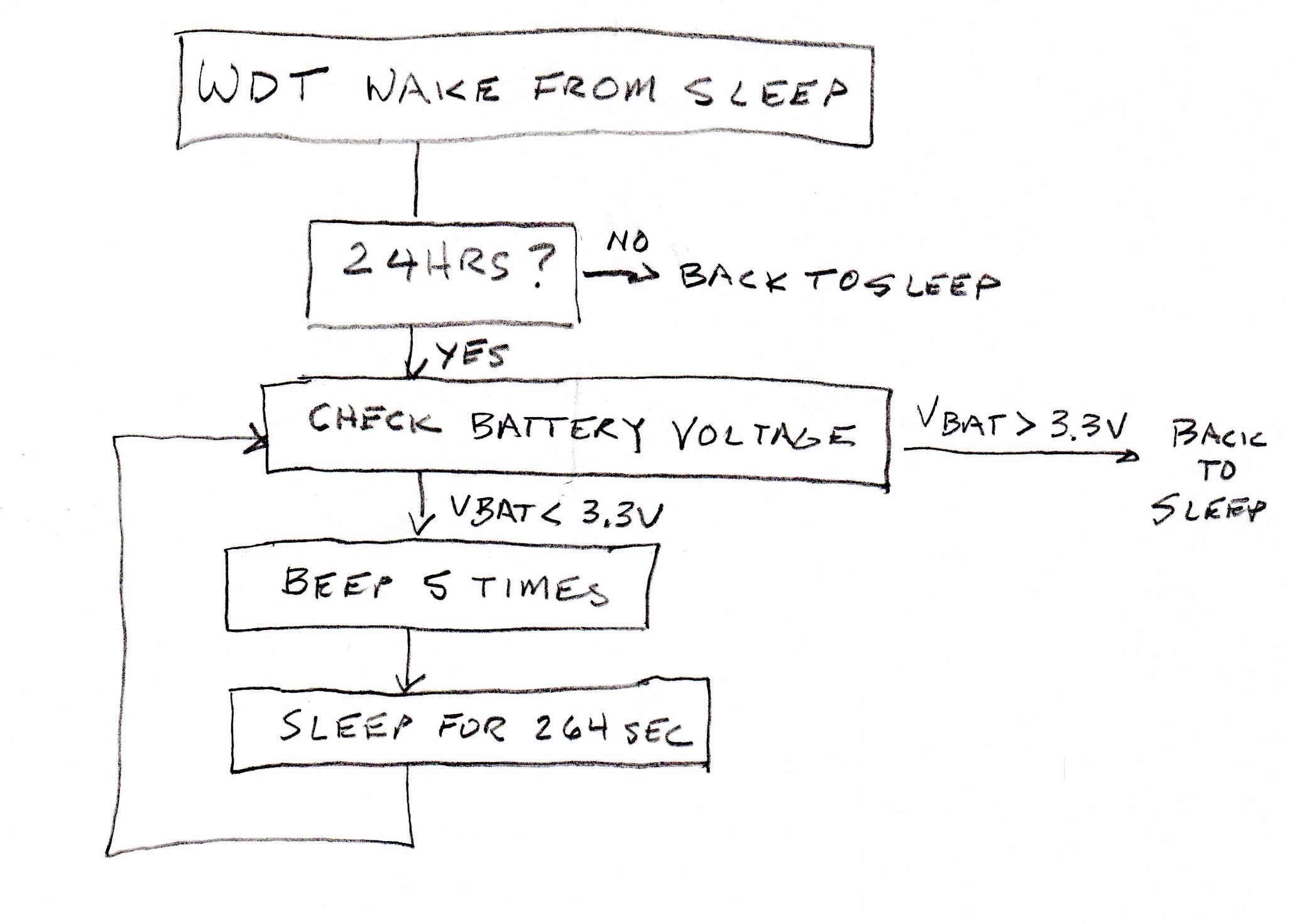 The WDT wakes up the PIC every 264 seconds. This routine counts out 24 hours before it checks the battery voltage. If the battery voltage is above 3.3V then the 24 hour timer is reset and the cycle begins again. If the battery voltage is below 3.3V then the PIC will beep 5 times (so as not to get it confused with a smoke detector) and go back to sleep until the WDT wakes it again to repeat the battery voltage check. I'm hoping that it won't do this at 2:00am.