Dean Netherton
-
Overclocking the Turbo CPU - attempt 1
02/17/2026 at 08:07 • 0 comments(This post is mirrored on my personal site at: https://www.dinoboards.com.au/2026/02/17/overclocking-turbo-cpu-1.html)
My Turbo CPU (both the Yellow and Stegosaur versions), run a stock Z80 at its maximum officially supported speed (for the DIP40 version) of 20Mhz. As mentioned in previous posts, the Turbo CPU runs the CPU at 2 different speeds - the slow standard speed when accessing I/O devices (such as the VDP or SIO/2 modules). And the boost speed (20Mhz) when accessing memory or crunching instructions.
To date, any attempt to ‘overclock’ the CPU, resulted in non-operation. I didn’t think this was a limitation of the CPU so much, rather a limitation of the logic chips I use to switch between the 2 clocks.
If the CPU is running at its high turbo speed, and attempts to initiate an I/O operation - then the logic needs to activate very quickly to stretch and sync up with the slower clock. If it doesn’t get the speed of the CPU down quickly enough, then the targeted I/O device might not see the incoming request from the CPU - or have sufficient time to respond.
Nonetheless, I thought I would have another look to see if I could get some more ‘performance’ from this module - and I ended up discovering a couple of things:
- The system did not always seem to downgrade to the standard speed when doing I/O operations!
- The overclocking issue was perhaps due to the timing of the generated WAIT signals - and not related to the clock speed slow down challenge.
I had a bug
When I looked at the clock signal and IORQ signals on my oscilloscope - I was very surprised to see the clock speed did not seem to slow down every time the CPU issued an IORQ request - I struggled to believe my eyes - how did this not cause reliability issues? I can only assume it was infrequent enough to not manifest in my specific hardware and testing.
It seems on close inspection, when the Z80 is doing an IORQ write, the duration of the IORQ is sometimes too short for the clock slow down system to activate. Reads seem to always trigger the slow down.
Lets have a look at some traces of the situation:
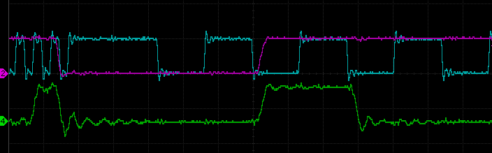
I/O Read Operation:
![Timing Trace of IORQ and CPU CLOCK]()
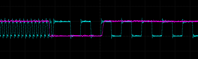
The above trace shows the CPU Clock (blue) going from its fast rate to slow rate, when the IORQ (purple) goes active low. There after, the clock stays in the slow rate (for a total of 31 ticks). The green trace is the RD signal - indicating that this is a read operation.I/O Write Operation:
![Timing Trace of IORQ and CPU CLOCK]()
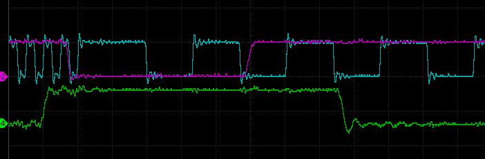
This trace shows a similar transition - but this time for a I/O write operation (green RD is in-active HIGH)I/O Write Operation (without slow down):
![Timing Trace of IORQ and CPU CLOCK]()
And this trace shows the fault. The clock has briefly 'stretched' during this I/O write, but the clock did not transition to the slow rate. I am not sure why, or if its even related, but the IORQ (purple) goes low at a different point relative to the clock (blue) phase - it seems to be a fraction later than the previous trace. This small delay seems to be enough to fault the clock slow down system.Despite not observing any reliability issues, I thought it was best to fix this.
What was the cause?
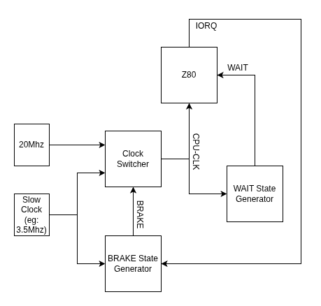
Now to understand the cause, we need to dig a little into the design. In the Turbo CPU module there are 3 main logic systems that work together.
- A WAIT State Generator - this is implemented in a PLD and generates WAIT states for the CPU, based on the position of the speed slider switch.
- A BRAKE State Generator - this is implemented in another PLD and generates a signal that selects which clock to use (the Turbo 20Mhz clock or the standard slow clock). It also incorporates a counter to hold the CPU in the slow mode, for 31 clock cycles.
- Clock Switcher - this is implemented with a couple of TTL chips - and its responsible for delivering the appropriate clock signal to the CPU - and ensuring a clean switch over from one to the other.
![Turbo CPU Block Diagram]()
Now the 2 PLDs mentioned need to have their own clock signals to drive their logic. The WAIT State Generator is driven by the current active CPU clock. So it might be the slow or fast clock - depending on the current active speed. The BRAKE State Generator is driven by the SLOW clock always.
The problem arises when the CPU is running at its high speed and generates its IORQ signal. Given the BRAKE State Generator is driven by the slower clock, it will take a bit of time before it fully latches the BRAKE signal. And sometimes the timing and phase difference of the two clocks would mean that the BRAKE signal does not get latched before the CPU has finished its IORQ operation - thus it never switches to the slow clock speed for the required 31 clock ticks. (At least, thats what I think is happening!)
The Fix
The best fix, that does not not require any hardware changes, is to update the WAIT State Generator to produce an additional WAIT state for IORQ requests. This change will extend the time of the IORQ periods slightly, enabling the BRAKE State Generator to respond in time.
In the original PLD code, there is the following bit of logic, that determines when a WAIT signal is to be generated.
MR = (MODE_NORMAL & MREQ & !RFSH & M1)
   # (MODE_MIDDLE & MREQ & !RFSH)
   # (MODE_FAST & MREQ & !RFSH);
This code was changed, as below, to now also generate a signal WAIT state when an IORQ operation is requested.
MR = (MODE_NORMAL & MREQ & !RFSH & M1)
   # (MODE_MIDDLE & MREQ & !RFSH)
   # (MODE_FAST & MREQ & !RFSH)
   # (!MODE_NORMAL & IORQ);
# is OR & is AND MODE_XXX is the position of the slider switch
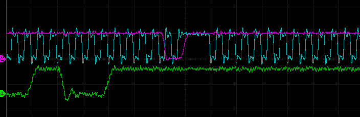
A simple fix. The following capture from my scope, shows the CPU clock rate (in blue), transitioning to the slow rate, when the IORQ (purple) trace goes active low. And it now always seems to correctly transition.
![Timing Trace of IORQ and CPU CLOCK]()
BLUE TRACE - CPU CLOCK
PURPLE TRACE - IORQ REQUESTBut I still could’t overclock the system beyond the 20Mhz rate – I did eventually - but will leave it to the next post to describe how.
-
Stegosaur MSX YM2413 Music
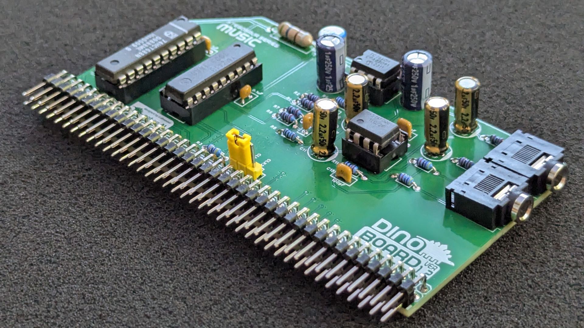
01/23/2026 at 05:05 • 0 commentsNext module to be downsized, is the MSX YM2413 Music Module.
![]()
This new module, is similar to the Yellow MSX Music kit, with some cool updates and improvements:
Improved Sound Quality
When I started designing and developing kits for the RC2014 platform, I only had a limited knowledge of digital electronics - just enough basic knowledge and understanding to work from. A lot of digital electronics is just ‘boolean’ logic and some flip-flops – this I kind of knew – not sure how – I guess some of the things I did as a kid had stayed with me.
There are a lot of online tutorials, blogs, helpful forums, that made my goal of re-creating a MSX based computer, seem at least a possibility for me.
Though, as with most learning experiences, its the lack of understanding of what you don’t know (those unknown unknowns), that can present some real confusing situations. I had a few of those - and probably still have more to come!
But I also knew, I knew nothing about analogue circuits. Things such as power supplies, and audio stuff - thats just some dark magic!
So when I attempted to design the MSX-MUSIC module, based on the YM2413 chip, I ended up doing a lot trail and error experimentation, to figure how to use these op-amp things, to amplify the audio signal.
The first versions worked, but had a very poor signal to noise ratio. The digital interference of the rest of the computer would always just bleed into the sound mix. That irritating digital noise would never quite go away.
I introduced a LC filter on the power supply (an inductor and capacitor) - this helped a lot with the digital noise. But the op-amps stage was still far from optimal.
With this version, I have further tweaked the op-amps stage to avoid rolling off the higher frequencies, whilst also reducing the noise considerably. In addition, it now has 2 op-amps - to enable its stereo operation.
I certainly won’t be getting a job at any high end audio manufacturer - or any audio equipment manufacturer for that matter - but I can honestly say - I have designed an op-amp amplifier circuit that actually works! Well done me.
Pseudo Stereo Output
Like the updated GAME module, I have updated this module to support a stereo mix. Whereas the GAME’s YM2149 has 3 audio outputs that are spread into a stereo mix, the YM2413 has only 2 audio outputs: Melody (MO) and Rhythm (RO).
The new design has a partial left/right mix for these 2 signals - there is a small resistor between the 2 signals, so that its not producing a full rigid left/right separation.
The audio received from the GAME module’s output (via a short 3.5mm audio connector) - is passed through and its stereo signal is maintained. Check out the short video below, demonstrating both the MUSIC and GAME audio mixed together.
MSX-MUSIC ROM extension split into a separate module
Due to the smaller PCB, its not possible to include the MSX-MUSIC ROM for MSX-BASIC extension. If this module is only used in a stock RC2014/RCBUS RomWBW build, the ROM module is not required nor is it compatible.
For a full MSX configured system, the ROM module can be installed separately.
Dropped the on-board clock
And just like I did for the Stegosaur GAME module, I dropped the on-board clock generator - and sourced the clock signal from the main bus (CLK1 or CLK2).
Demo
More details
I have more details of the module and schematic up on my site now: https://www.dinoboards.com.au/stegosaur/music/
And its listed on my shop for sale as a kit https://shop.dinoboards.com.au/product/stegosaur-msx-ym2413-music/
And for the MSX Builds - the MSX-MUSIC ROM Module: http://www.dinoboards.com.au//stegosaur/music-rom/
-
Stegosaur YM2149 Game Module for RC2014/RCBus
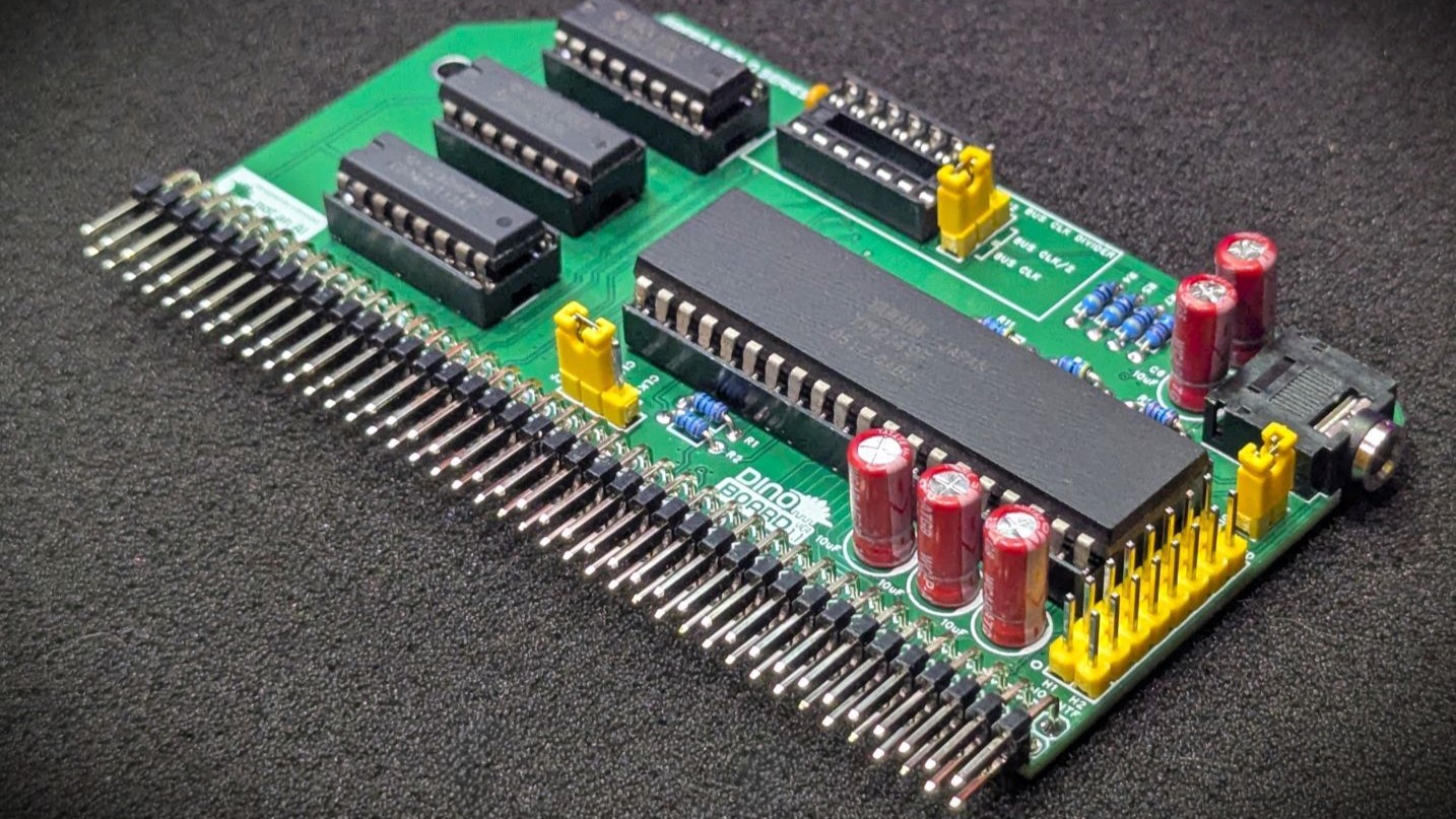
01/13/2026 at 04:33 • 0 commentsNext module to be downsized, is the YM2149 Game Module
![]()
Here is the new module in the Stegosaur series. The Stegosaur YM2149 Game Module.
Like the other modules, it is an alternative to the Yellow Module. With some difference - and the big visual difference is the height reduction.
Let me highlight some of the key changes:
Pseudo Stereo Output
By popular demand, I have updated the design to incorporate the ‘golden ratio’ stereo mix. I am not 100% sure where it first appeared - I see references to https://hw.speccy.cz/ayinterface.html - so not 100% sure who to credit. Many kits based on the YM2149/AY-3-8910 chip have implemented this output circuit.
![]()
The chip has three separate channel outputs (A, B and C) - and by using some resistors dividers to spread the signals across the left and right channels, we get a very full wall of stereo sounds for our games and music playing programs.
Updating the GAME module to produce stereo output, also meant I needed to update the design of the MSX Music module to pass-through this stereo mix. So its design also had to be updated. More on that in the next post.
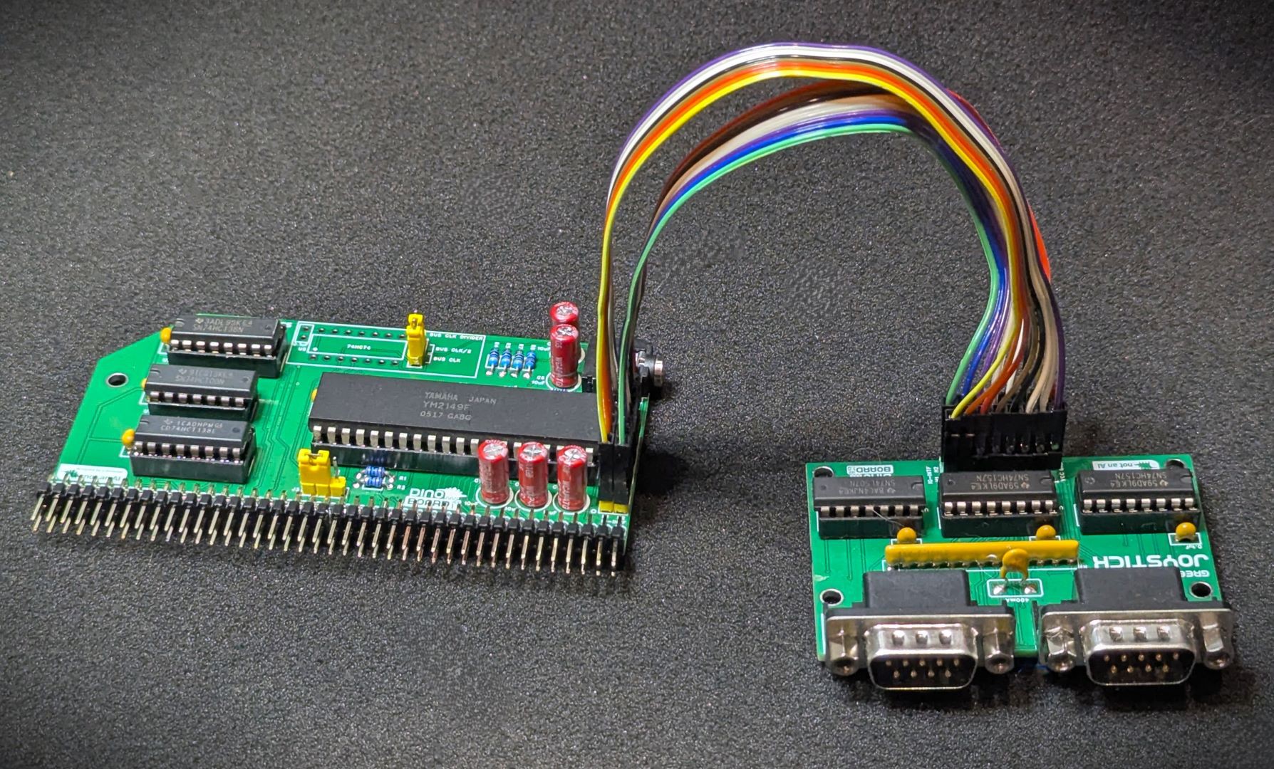
Controller Connectors
In comparison to the Yellow MSX module, I remove the game controller DB9 connectors to an optional expansion board.
This new revised packaging should help anyone who wants to place their kit in a custom designed case. As most games and applications will work just fine using the keyboard, the lack of a controller interface is not too big a deal.
![]()
Optional Support for AY-3-8910
An extra jumper and an optional on-board clock divider circuit, and we can support the very similar and compatible chip - the AY-3-8910.
Dropped the on-board clock
In the interest of saving space and simplifying as much as possible, I removed the on-board clock generator. This module is expected to get a clock signal from the main bus (CLK1 or CLK2). Typically that will be generated by the V99x8 RGB Module - which will be used by this module and some other modules of the series.
I have more details of the module and schematic up on my site now: https://www.dinoboards.com.au/stegosaur/game/
And its listed on my shop for sale as a kit https://shop.dinoboards.com.au/product/stegosaur-ym2149-game/
-
Next module to be downsized, is the Turbo CPU module.
01/11/2026 at 03:56 • 0 commentsNext module to be downsized, is the Turbo CPU module.

Stegosaur Turbo CPU Module I manage to reduce the PCB size, by removing the on-board slow clock, and relying on an external slow clock source, such as a RC2014 Dual Clock module, or the RGB Video Module.
I am particularly proud of this module – as it was perhaps the first design I did that wasn’t so much based on stock MSX schematics.
For those that don’t know - the Turbo CPU module runs a standard Z80 40 pin chip (Z84C0020PEG), at up to 20Mhz. Its not overclocking it - nor does it require the backplane clock to run at 20Mhz. It dynamically switches the clock of the CPU between the bus-clock and its 20Mhz turbo boost speed.
The clock speed of the CPU is switched to the bus-clock, when the IOREQ line goes low. It holds the processor at the ‘slow’ bus clock for 31 slow clock ticks.
This means when the processor is communicating with any I/O device, its running at the modest bus clock speed - to ensure compatibility. But when its just ‘processing’ or reading/writing to memory - it runs at its boost speed.
This turbo boost process gives it a lot of compatibility with existing devices - but can really improve those very slow IX/IY+n operations a lot.
It was an interesting challenge, to do the clock switch - can’t just do an immediate switch between the two clocks. You have to ensure when it transitions from one clock to the other, that its not done too quickly, that we end up momentarily having a super high frequency sent to the CPU’s clock input; the 2 clock sources (20Mhz fast and the standard bus clock) are not in phase - so when switching it would glitch unless it waits. When transitioning, the clock is ‘stretched’ a little until we sync up with the other clock.
This module will work just find as a replacement for the stock RC2014/RCBus Z80 processor modules as well as a perfect speedy CPU solution for the MSX2 configuration.
I have more details of the module and schematic up on my site now: https://www.dinoboards.com.au/stegosaur/turbo-cpu/
And its listed on my shop for sale as a kit https://shop.dinoboards.com.au/product/stegosaur-turbo-cpu/
-
New Series of Modules
01/04/2026 at 02:55 • 0 commentsIt’s a new year, and I have some new modules under development.
I have started to look at updating my Yellow MSX series with new PCB designs that fit the more conventional RC2014/RCBus height of around 5 to 5.5 centimeters.
The original Yellow MSX PCB have a height of around 8cm - near double the typical height. The greater height was generally required, as I needed the extra PCB space to fit all the components for each of the various modules.
In particular, the V99x8 module is quite a challenge - the 64 PIN DIL chip takes up almost half of the PCB area of a conventional height of ~5cms. Then when you add the RAM chips (4 of them) - well its just not physically possible.
That is, unless I reduce the RAM to just 64K (down from the 128K). With just 64K, it is possible to fit all components onto the smaller PCB. The lower RAM still allows the VDP to displays all the game graphic modes, just with less RAM available for paging - so some games might not work - but I think many still will.
But I still want to support the 128K of VRAM - and in fact, it would be very nice if I could extend support to the VDP’s maximum of 192K VRAM.
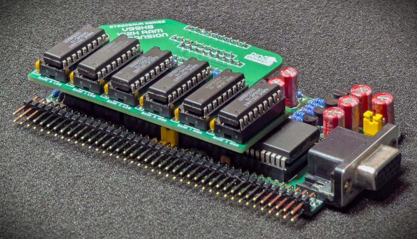
What I ended up designing is a main board - at the 5.5cm height, with support for 64K - and an ‘expansion board’ that allows the module to support the full 192K. The height is still the same, but the width is increased a bit.
Here is a picture of the new design, with the 64K RAM on a single 5.5cm PCB:
![]()
And here is it with the expansion installed:
![]()
With the expansion board, its a tight fit - and the width of the 2 combined PCBs does extend beyond the RC2014/RCBus’s typical spacing. (If the RAM was soldered directly and not socketed it would probably fit in the BUSs’ standard spacing).
I am calling this series of boards - the Green Stegosaur Series. The intention is that the series will be compatible and mostly the same as the Yellow MSX series, but with the smaller height. It will probably necessitate that some modules are split into 2 - eg the MSX Memory module will definitely need to be split into 2 separate PCBs. So this series will probably require more slots on the backplane.
If you are not interested in MSX, though, this new Video Module’s form factory, might be a better fit for your RC2014/RCBus rigs.
I have more details of the module and schematic up on my site now: https://www.dinoboards.com.au/stegosaur/v9958/
And its listed on my shop for sale as a kit https://shop.dinoboards.com.au/product/stegosaur-msx-v9958-rgb/
-
Art is never finished
06/07/2024 at 06:13 • 1 commentArt is never finished only abandoned
Don't worry - I haven't abandon the project.I've been working on the MSX Music Module (and listed a new revision in my Tindie store).
This revision further reduces some of that annoying digital background noise that could be heard when no music or sound playing. Its still emanate some background noise -- I think it be very hard to eliminate as so much of the various RC2014 modules will generate a lot of EMF noise.
The latest revision (1.9), increases the gain of the op-amp stage and adjusted some of the capacitors on the feedback. This seems to improve the signal to noise ratio, and it also improved its higher frequency responses. Its sound much brighter.
-
CH376 Module Challenge
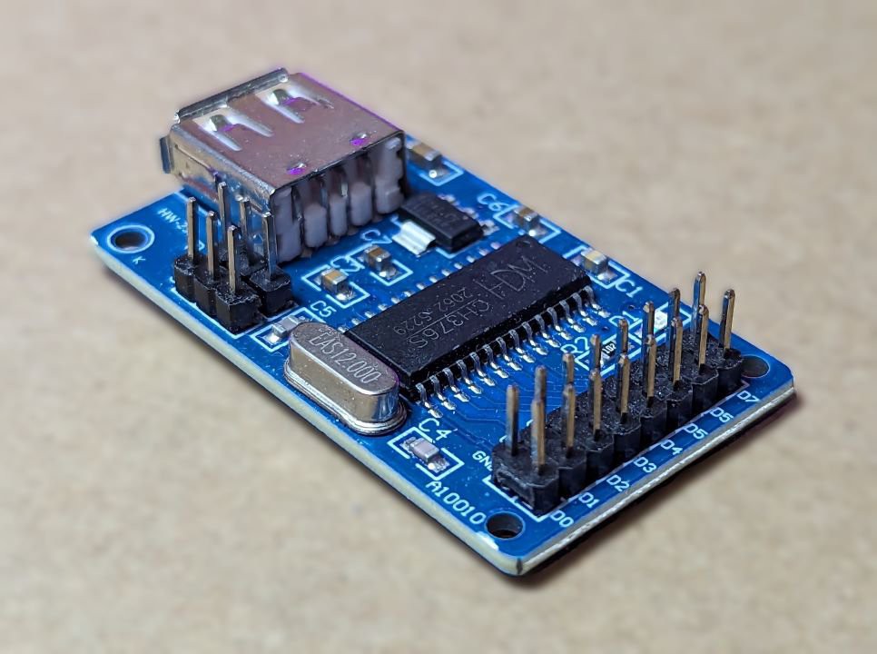
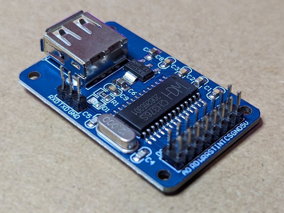
11/19/2023 at 00:24 • 0 commentsCan you tell the difference between these modules - they are both sold as CH376 Modules?
![]()
![]()
Both were purchased from ebay/aliexpress traders. Both are sold as CH376 modules. Both have the same CH376 chip.
The one of the left though, has a different pin out. Notice the 2x3 header pin. Whereas, the one on the right only has a 1x3 pin header. And just to add to the change, the main headers have been swapped. For the left/original, the outermost pins are the data lines, and for the right, its the inner most pins.
This alternative form-factor is not compatible with my PCB design.
On my Tindie store, I had packaged up some kits - and only at the last minute did I notice this very different pinout/form factor change. I very nearly sent out kits with an incompatible module!
I have not been able to source any more of the module as shown on the left. Only seem to get the one on the right.
It now seems that the ebay/ali-express traders are only selling the one on the right -- even if their product page shows the original 2x3 pin header. You just can not trust what you will end up getting.
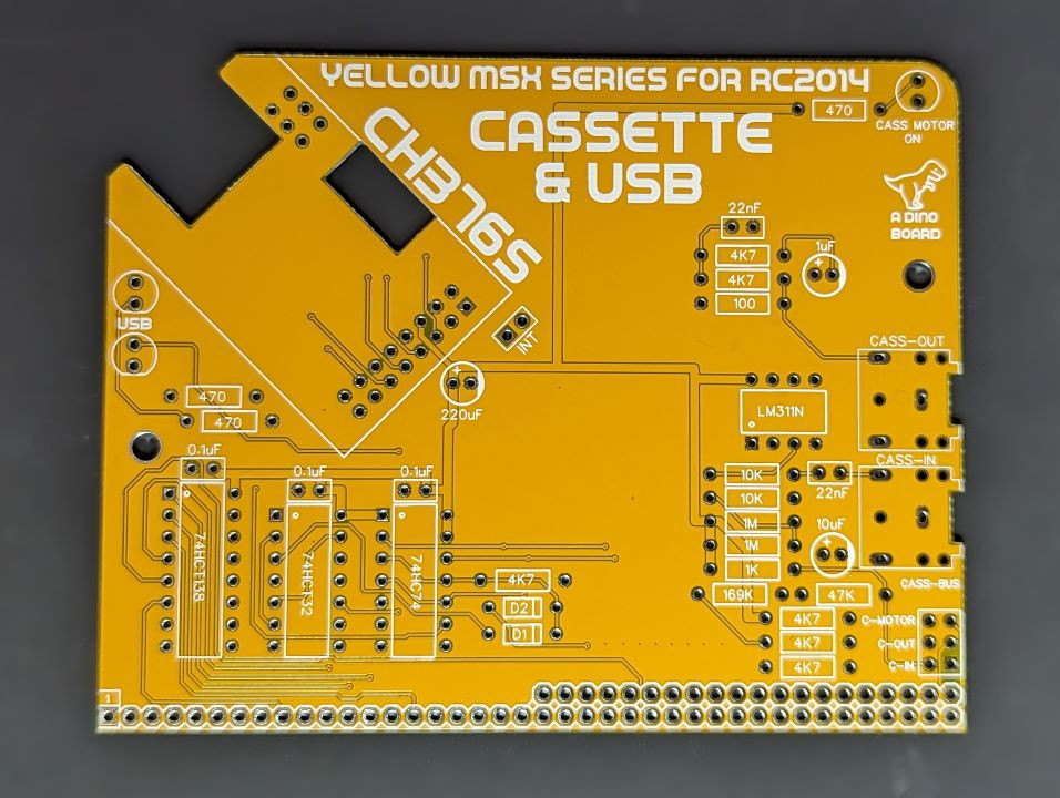
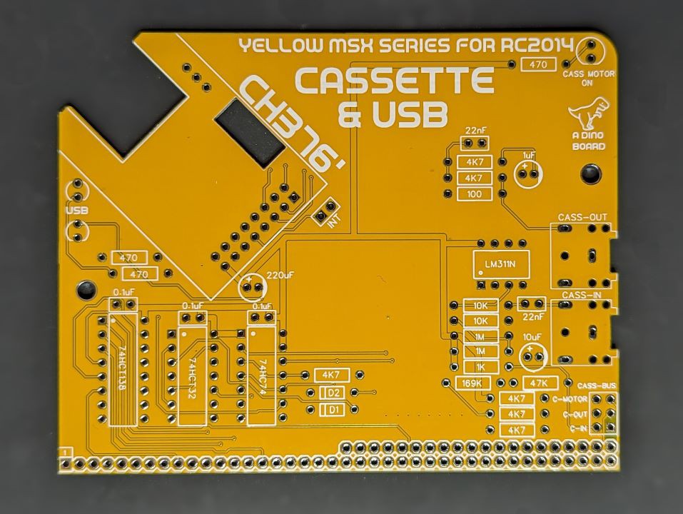
So I had to redesign the PCB for my Cassette+USB kit to accommodate the change. As this is just a form factor/pin out change - the software and electronics all still work the same. Only need to re-route and reposition the cut outs on my PCB.
So now I have 2 PCB versions for this kit, to accommodate the 2 form factors:
![]()
![]()
I have just assembled a kit using this new module form factor - and so far all seems to work just fine. I do need to do a bit of testing to double check everything. So if u are waiting to get one of these kits - I can hopefully have new stock listed next weekend.
-
USB Software updates
10/28/2023 at 23:58 • 0 commentsI have been updating the USB software over the last week or so and making some progress with support for additional hardware types.
USB Keyboard
I managed to get a USB keyboard to work. At this stage, it has very limited functionality. (arrow keys for instance don't work). But I was able to boot and control the kit without the matrix keyboard attached - using a USB keyboard only.
Almost certainly, few games would work with the USB keyboard, but MSXDOS/NEXTOR and CP/M apps seem to work just fine.
The kit would need the PPI card (part of the keyboard kit) as without the PPI, the system will not boot.
I still need to add extra support - arrow keys, caps lock -- and I do wonder if I am able to control the keyboard's capslock LED.
FTDI Serial Adapter
This one is interesting. Have a couple of USB/Serial adapters I've used to connect my PC to the original RC2014's SIO/2. But I thought, can I now go the other way?
But this USB adapter is a vendor specific class. That is, the USB protocol to control the adapter is not part of the USB specification - its the manufacturer's proprietary protocol. I could not find any published specification - but there is the public Linux driver for it. The code is quite simple, and so by reviewing that code, it was quite easy to figure out how to configure the adapter and send/receive data over the serial chip.
This is still very early in the development - managed to get some experimental code to do a loop back test - (connect the TX/RX lines of the adapter). The code confirms what it sends is also what is receives. Have this operational at baud rates up to about 38400 - I think I can go higher!
I've only coded for the specific FTDI 232R chip - as I don't have any other chips to test and verify. Including from other manufacturers.
Also I am starting to run out of ROM space. All my USB code, mostly written in C using Z88DK/SDCC compiler needs to fit in about 16K. I am at about 15K! All part of the challenge.
MSX COMPATIBLE BOARDS FOR RC2014
Create a series of boards designed for the RC2014 bus to achieve MSX/MSX2 compatiblity