Close
0%
0%

DIY JBC Nano Controller

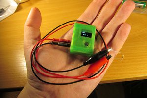
DIY controller for JBCs Nano (NT115) Soldering irons

Similar projects worth following
Everybody is this community knows and loves JBC for their high-end professional soldering irons. These are often considered to be the best on the market. But, being professional grade equipment, the price tag is also in the professional range. Since the majority of the cost is for the station, building controllers / stations for these has become quite a sport in the DIY community.

Why Nano and not T245/T210 as everyone else?

The JBC NT115 soldering iron is amazing, it's quite compact, has a slim cable and the grip-to-tip distance is really small. It's meant for super fine-pitched SMT parts, yet if you combine it with a larger tip, its powerful enough for most soldering needs. So, despite being a high precision tool, it is still use-able as a general purpose soldering iron.

Also, there is no real point in DIYing a controller for the larger irons from scratch, since there are already heaps of projects on the internet.

Economics of DIYing a soldering iron controller

Depending on the brand, the soldering station / controller is often the most expensive part of a soldering system. This make sense, since this is the most complex part as well. But, the stations are built from standard components (except the mechanical parts), so it is fairly easy to replicate the behavior of the station with a DIY solution.

In my case, the station (including tools individually valued at about 400EUR) is sold for approx 1200EUR. So the price tag of the station itself is about 800EUR. The DIY project cost me about 10EUR, so that's a huge difference. Fair enough, the original station supports two dual-channel tools while mine only supports a single tool. But extending the number of channels is cheap and more or less trivial from an electric point of view.

Of course, the original station will be better than mine from the mechanical point of view. While mine is a light-weight 3D printed plastic thing where you need to be careful not to melt the enclosure, the original is solid professional equipment.

Differences to the T245/T210

Both have similar tips with the heater and thermocouple embedded directly in the tip.

Plug

The most obvious difference is the plug, this immediately suggests that there are some more fundamental difference between the two irons.

Voltage

The NT115 system is designed for a much lower voltage. If I remember correctly, NT115 uses about 9V while T245 is more 20ish. Not sure how bad too much power is, but overloading the tip by a factor of 4 doesn't sound good. For reference, the C115 heaters have a (hot) resistance of about 5 Ohms, which would result in ~16W at 9V, so that's quite close to the nominal 15W of the tips.

Heater and thermocouple are in series

Despite the cable having three wires and the tip having three contacts, two of the contacts seem to be internally connected inside the tip. So, the only way to power the heater is through the thermocouple. This sounds odd at first, but that's just how it it...

Status of this project

Everything works pretty well, the heat-up times are JBC-like fast and the temperature is quite stable. I don't know the exact characteristics of the thermocouple, but from tests, I assume the sensitivity is about 9uV/K. It doesn't matter that much, since the temperature you need for a job depends highly on the tip and the job anyway anyway. The hardware supports to measure the supply voltage, but I'm not using it right now.

Under-voltage self destruct

One issue with the current hardware is a potential self-destruct scenario, if the supply voltage is too low. Since I'm using a low-side driver to drive a high-side P-Channel FET, the undervoltage lockout (about 4V) of the driver will force the FET ON when the supply voltage is too low. This may cause the tip or the mosfet to overheat. So always use a switching power supply since it will turn off anyway if you load it down that much.

schematic.pdf

application/pdf - 103.68 kB - 10/26/2020 at 14:45

Preview

  • Feature List

    Daniel11/24/2021 at 22:26 0 comments

    Since I consider this project finished now and I had this in use for a few month now, I guess its time to do a little summary of the features

    Supported soldering irons

    So far I only tested this with a JBC NT115 hand piece, but it should work for all soldering irons where the heater is powered through the thermocouple. This is certainly a minority of the available soldering irons though, since most have a separate wire for power. But I think some Hakko tips use the same design as well. If you intend to use a different iron with a different thermocouple, keep in mind that you may have to adjust the gain for the thermocouple amplifier.

    Power supply

    Since I didn't include a separate power supply for the gate driver, the maximum voltage is limited by the gate driver and the maximum gate voltage of the used mosfet. I run this at 12V and you shouldn't go much higher. This would be easily changeable, but since I designed this for low-power irons it never was a problem.

    Software features

    • Highly responsive temperature regulation for almost instant heat-up.
    • Two levels of standby/sleep modes controlled by a contact closed when the hand piece is in the holder (Could be a micro-switch or a contact closed between the sens line and the metal ring of the hand-piece).
      • Target temperature will be dropped to standby temperature as soon as the hand piece is in the holder.
      • After a delay the heater will be turned off completely.
    • Idle detection turns off the heater when the iron is not in use for some time but not in the holder.
    • Menu implementation on the display to set controller / standby parameters.
    • Persistent storage for all settings, including the current set temperature.

    Enclosure

    The enclosure I designed for this project is very basic and leaves lots of room for improvement. It's very light, so it doesn't feel high-quality at all. On the up-side, it is super compact while still having an integrated holder for the iron.

  • Noise issues

    Daniel11/03/2020 at 19:40 0 comments

    Unstable measurements

    While testing the temperature measurement, I noticed that the values were rather unstable. I quickly noticed this was caused by an unstable supply voltage. In the STM32 the ADC is referenced to VDDA, which is more or less VCC with filtering. I probably should have added more filtering / larger caps, but first I tried to address that issue in software.

    Compensate against VREF

    The STM32 have an internal 1.2V reference. This reference can be measured by the ADC and the result can be used used to compensate other ADC values for varying operating voltages. The ST_VREFINT_CAL value is a constant for the ADC readout of the internal reference at VDDA=3.3V. The lower the operating voltage, the higher the reference reading will get.

    vin = ((3300ULL * ST_VREFINT_CAL) * <ADC_IN>) / <ADC_REF> / 4096; 

    This compensation pretty much solved the noise issue, but from time to time a few outlier caused the controller to look a bit unstable.

    Outlier detection

    Since the signal is now pretty stable over all, we only have to address a few outliers. This is done by calculating the difference of the average difference to the average of the last 16 readings.

    If err is below a threshold, the value is accepted and used for the controller. If the values is rejected, the controller re-uses the last reading. This is no problem, since the controller cycles are rather short, typically 10ms. The new value is added to the window in any case, so a sudden jump in the values will not stop the controller form working.

    What causes the noise / how to avoid it?

    The two methods eliminate the noise issue, but it would be better to figure out, why we have noise in the first place. I've been measuring the VCC with an oscilloscope and can confirm, there is noise on the VCC line. Its not just minor noise, there are some larger drops in the supply voltage. My suspect is the display, but since I soldered it onto the board, there is no easy way to test without it. I tried to add some caps across its voltage pins, but it didn't improve much. So for now I leave it like that since its working and I'm kind of happy with the software solution.

  • Little flash, big trouble

    Daniel10/26/2020 at 14:40 0 comments

    16KB flash should be enough for everybody...

    ... at least that's what I though when selecting the controller for this project. After all, controlling a soldering iron is not a very complex task, so I just got the smallest STM32F0 available. Then I started to write the code and figured out, I was gravely mistaken. The whole project with the features I wanted would have never fit into that controller, so I hade to find ways to save flash.

    HAL is huge

    Initially, I wanted to build this with the STM32Cube HAL. I've never used it before, but since it's kind of standard I wanted to give it a try. But once I set up the project, I realized, this is a bad idea! Even a very simple test program already takes 10k, so that's not gonna work.

    libopencm3 to the rescue

    In all my other STM32 projects, I always used the libopencm3. That's a free HAL for Cortex-M ARMs. It does not come with the nice graphical pin and clock assignment thingy, so it requires a bit more data-sheet diving. And I think it makes a slightly worse job at abstracting the hardware, so the code is a bit more target specific. But its WAY smaller, so that's why I used libopencm3 for this project as well.

    Fonts aren't small either

    Since I'm using a graphic display, I needed fonts! And since I don't want all text in the same font size, I need more than one of those. I used bitmap fonts, which makes fonts with large letters quite big. And so when I ran out of flash again and decided to do something about the font size.

    Strip unused characters

    I realized, that the biggest font (16x26) is exclusively used for the temperature display in the main screen. But there only the numbers and the 'C' is needed. So the first reduction was by creating a copy of that font that only contains 11 symbols instead of a full char set.

    Compress the font

    Even with the reduced char set in the large font, the flash was still to small, so I decided with experimenting with ways to compress font. For large fonts, this is usually done by using vector fonts. But for smaller fonts, this gets ugly results, so that's not really a good option. Instead, I was looking for ways to compress the bitmap font. Since after compression, the sizes of the single bitmaps won't be the same, an offset table is needed so the symbols can be found again. This further increases the size of the compressed data so an efficient compression is needed to reach the break-even.

    Run-length encoding

    At first I experimented with different forms of run-length encoding, but the resulting compression ratio was disappointing. The following example shows a very simple run length encoding, where only blocks of '0' are encoded. Blocks of '1' or mixed blocks are stored raw. This shows that even with data that is very compression friendly and an optimal setting for the block length, the compression ration isn't very good. For small data sizes, the size of the headers just eats the space savings, so the data needs to be very compressible to even reach the break-even.

    Code: 0xxxx -> xxxx bits of 0
          1xxx  -> xxx bits of uncompressed data
    
    Original: 00000000110000000000  20 bit
    Encoded:  0100010101101010      16 bit
              ^8x0 ^2x* **^ 10x0

    Geometric compression / Bounding boxes

    I decided to try an encoding scheme, where the break-even is very early. When looking at the font, I figured that most chars do not fill the whole bitmap. So I only stored the used area of the char and have a small header containing the position and size of that area. These headers are tiny and there is only one header for each char. For a 11x18 font the header is just 18 bit (x/w each 4 bit + y/h each 5 bit). So the break-even is reached as soon as we can avoid storing a single column.

    Header: xxxxwwwwyyyyyhhhhh 18 bit
    x: Offset (x)
    w: Width of the stored region
    y: Offset (y)
    h: Height of the stored region 

     Below is the summary of the compression efficiency for the used 11x18 font

    11x18 Font 95 Chars
    Raw size:   11x18 = 198 bits -> 25 bytes (rounded) per char
                 => Total: 2375 bytes
    
    Compressed: Offset table:...
    Read more »

View all 3 project logs

Enjoy this project?

Share

Discussions

komarudineuis wrote 01/21/2023 at 20:56 point

sorry daniel.
can i request you to upload a Hex File. so I can upload using ST-LINK.
I'm not very familiar with the STM32 Processor

Thanks daniel

  Are you sure? yes | no

bulan7x wrote 11/22/2022 at 22:16 point

hi daniels,,,
I'd like to ask,
UCC2751 mosfet in my place is very difficult, what is a suitable replacement?
and what program is used for C File compiler?

thanks daniel

  Are you sure? yes | no

Daniel wrote 12/07/2022 at 21:32 point

Oh, apparently I messed up the schematic. The current part number is UCC27517, this should be quite easy to get globally (even LCSC has it)

The software is built as a makefile project with just the arm toolchain, check out the README on my Github page for details (https://github.com/Winkelkatze/jbc_nano_solder#readme)

  Are you sure? yes | no

mpeekree wrote 07/14/2022 at 13:21 point

need value of C13,L1,D1 & Y1 ?

  Are you sure? yes | no

Daniel wrote 09/04/2022 at 11:38 point

Yeah, was a bit lazy making the schematic and omitted some values :)

I have updated it recently, so there should be everything there now

  Are you sure? yes | no

mpeekree wrote 09/04/2022 at 15:14 point

thank you for great schematic, an isolated dc-dc converter is a great option for minimal the noise, and using RT9193-33GB will be a good improvement.

if my board was finish in test, maybe i'll make some improvement. still learn how program this project. 

  Are you sure? yes | no

Daniel wrote 09/14/2022 at 21:38 point

I just realized, that one value from the schematic was wrong. R5 should be 5K instead of 10K, to set the gain for the thermocouple to 501 (instead of the original 1001). I also added this value as a constant in main.c ("THERMOCOUPLE_GAIN").

If you don't have a 5k resistor at hand, you can just stack two 10k resistors, or use a slightly different value and adjust the THERMOCOUPLE_GAIN in main.c

  Are you sure? yes | no

mpeekree wrote 09/15/2022 at 03:15 point

can i use 5,1k for r5 ? 

  Are you sure? yes | no

Daniel wrote 12/07/2022 at 20:48 point

Totally missed your reply :D

But yeah, a slightly different value for the gain resistor is fine. Then you could even just compensate that by changing the sensitivity value in the menu.

  Are you sure? yes | no

ra-ma wrote 12/31/2021 at 10:18 point

Great project I'd like to build. One question in regards to the STM32F0 - as you mention that flash is small with 16kB - would it be possible using the STM32L031F6P6 as this has 32kB flash and is available? Any modifications at the code needed for such a change?

  Are you sure? yes | no

Daniel wrote 01/19/2022 at 19:36 point

The pinout of both seems to be compatible, but swapping these controller is always a bit tricky if you are not comfortable with troubleshooting the code. For instance some hardware may be named differently (e.g. LPUART instead of USART), or some clock related stuff may change.

There are also some 32K variants of the F0 with the TSOP-20 footprint, but availability is indeed a problem.

If you try to change the micro, let me know. I'm curios how well this works as well :)

  Are you sure? yes | no

bossekilund wrote 12/29/2020 at 12:14 point

Hey.

Have anyone made this project beside Daniel ?

If , can / will you then share your experience with me. Thanks ! 

@Daniel do this also fit for the "old" NT105 ?

  Are you sure? yes | no

Daniel wrote 01/03/2021 at 12:17 point

Hi,

sadly, I don't have a NT105 and there is only very little Information about these on the internet. But it should work as long as they have a similar heater resistance and the TC is in series with the heater.

  Are you sure? yes | no

bossekilund wrote 01/04/2021 at 11:10 point

Thanks Daniel.

Do you have any links to your project with the program code and the 

print layout file.

I like to try to make a "copy" of your project and test it with a NT105.

  Are you sure? yes | no

Daniel wrote 01/04/2021 at 17:40 point

  Are you sure? yes | no

Richard Sim wrote 11/12/2020 at 08:46 point

Hey, I think you've mis-understood the iron/tip pinout with regards to the TC/heater connections. The header and TC are in series with a common connection between them. You power the heater through one wire and the common, and sense the TC with the remaining wire and the common - you shouldn't be powering the heater through the TC.

  Are you sure? yes | no

Daniel wrote 11/26/2020 at 20:04 point

It sounds odd and I didn't believe that at first, but the two pins are indeed shorted within the tip. At least I couldn't detect the TC voltage between these two pins. So the only way to power the heater is through the TC.

Even the cable has three wires, so it doesn't make any sense. My guess is that JBC decided this quite late in the design stage. Probably couldn't fit all the connections withing that small tip.

  Are you sure? yes | no

Similar Projects

Does this project spark your interest?

Become a member to follow this project and never miss any updates