( A break in project updates due to a new puppy )
With the circuitry defined, prototype tested and schematic drawn, it was time to turn my attention to something a little more permanent than a breadboard and some snippets of test code. My usual go-to software for PCB design is KiCAD and On-Shape for 3D modeling. However, with Autodesk combining both into a single application (Fusion 360), I decided to see if the combination was helpful.
I am impressed with Fusion 360 - especially since it has impressive surface modeling tools along finite element analysis, flow modeling and 3-axis milling and lathe CAM built in. Eagle is great too, although the interface is still as clunky as I remember it being before Autodesk acquired as it doesn't conform to the current day "standard" of interfaces (eg right click doesn't always open a context sensitive menu, it rotates a part).
But Fusion 360 also has its quirks; every save creates a new version. And as someone who was taught to save frequently in case of a crash, some of my designs had upwards of 100+ versions. It seems that in a rush to compete with OnShape's cloud solution, Autodesk was a little clumsy in its implementation.

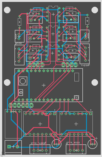
The comparators are at top; with the mode knob encoder on the left and thermostat encoder on the right. While not a mistake, it's a minor annoyance that I swapped the position of the stepper drivers: thermostat on the left, mode on the right.

While Eagle's use does seem widespread, finding reliable component libraries (especially that have 3D models) is quite difficult. I imagine support is better if you're a commercial customer who is about to buy hundreds of thousands of parts. While I have dreams (and most of the parts) to build my own pick-and-place, the quantity of PCBs hasn't yet warranted the investment. So I'm left with creating my own component libraries that cobble together custom schematic symbols, layouts and 3D models. And I don't always get those correct.
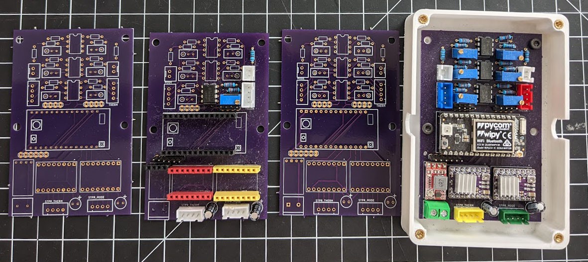
PCBs from OSHPark (left-to-right) (1) First revision with many of the through-holes too small to fit the component pins. (2) Using headers, I was able to populate some of the first version board enough to test the circuitry. (3) Second spin of the board, with the hole sizes being the only needed change. And (4) fully populated, along with its enclosure.

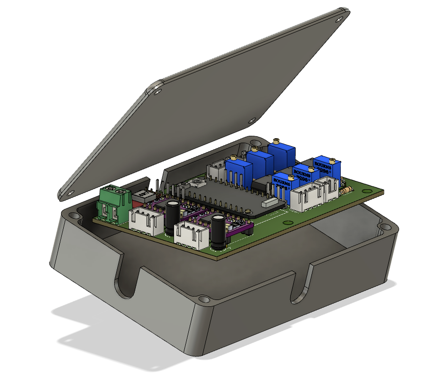
For all of Fusion 360 and Eagle's quirks, it was super helpful to design the enclosure based on the 3D model that it derived from my PCB layout. It definitely prevented extra manufacturing revisions for more complicated assemblies like the encoder and stepper mounts.
Discussions
Become a Hackaday.io Member
Create an account to leave a comment. Already have an account? Log In.