Frederic L
-
Final result
10/31/2020 at 11:52 • 4 commentsQuick in-situ programming and everything is now done. The video speaks for itself.
![]()
I'm very happy with the result, it works exactly as planned and I'm glad I have this small (and quite unnecessary, but I enjoyed the project) improvement in my MGA.
Happy touring !
Files available here :
-
Software (arduino code)
10/31/2020 at 11:34 • 0 commentsProgrammed using the Arduino framework.
I commented the code as much as I could, and it's fairly straight forward. Original 60 years old switch is debounced in software, and millis() function is used instead of delay() to avoid loop interruptions (we need to be able to read the switch state changes at all times).
The loop() function reads and interprets the switch state.
The wipe() function sends a wipe pulse when necessary.
#include <Arduino.h> /* I/O PARAMETERS */ #define PIN_WIPER_OUTPUT 3 // PIN to wiper relay #define PIN_INPUT_SWITCH 4 // Pin reading wiper dashboard switch position #define SWITCH_DEBOUNCE_DELAY_MS 50 // Switch debounce delay in ms #define TOGGLE_LIMIT_DELAY 2000 // Time to consider an ON-OFF-ON as a toggle /* INTERMITTENT CONTROL PARAMETERS */ #define INTERMITTENT_1_MS 10000 // Intermittent delay 1 in ms #define INTERMITTENT_2_MS 7500 // Intermittent delay 2 in ms #define INTERMITTENT_3_MS 5000 // Intermittent delay 3 in ms #define INTERMITTENT_4_MS 2500 // Intermittent delay 4 in ms /* WIPER MOTOR RELATED PARAMETERS */ #define RELAY_TIME_MS 500 // Duration (ms) the relay stays closed to initiate the wiper swipe uint8_t toggles = 0; // Track the ON->OFF->ON toggles uint8_t switchState = LOW; // Keep track of previous switch status uint8_t lastSwitchState = LOW; // the previous reading from the switch uint8_t forceWipe = false; // Force a wipe now unsigned long lastWipeTime = 0; unsigned long lastOffTime = 0; // Last time the switch was in the OFF position unsigned long lastDebounceTime = 0; // the last time the switch was toggled unsigned long debounceDelay = 50; // the debounce time in ms void setup() { // Initialize PIN modes pinMode(PIN_WIPER_OUTPUT, OUTPUT); pinMode(PIN_INPUT_SWITCH, INPUT); // If wiper switch ON at power up, activates wipers if(digitalRead(PIN_INPUT_SWITCH)){ switchState = HIGH; lastSwitchState = HIGH; } } void wipe() { // Wipe outputs based on switch position and toggle numbers if(switchState == HIGH) { int intermittentDelay = 0; // Wipers are on switch (toggles) { case 0: intermittentDelay = INTERMITTENT_1_MS; break; case 1: intermittentDelay = INTERMITTENT_2_MS; break; case 2: intermittentDelay = INTERMITTENT_3_MS; break; case 3: intermittentDelay = INTERMITTENT_4_MS; break; default: // Continuous wipers intermittentDelay = 0; break; } if(millis()-lastWipeTime > intermittentDelay || forceWipe) { //Send a wipe pulse digitalWrite(PIN_WIPER_OUTPUT, HIGH); lastWipeTime = millis(); forceWipe = false; } if(millis()-lastWipeTime > RELAY_TIME_MS) { // End the pulse after the required delay digitalWrite(PIN_WIPER_OUTPUT, LOW); } } else { // digitalWrite(PIN_WIPER_OUTPUT, LOW); } } void loop() { // read the state of the switch into a local variable: int reading = digitalRead(PIN_INPUT_SWITCH); // check to see if you just switched the button // and you've waited long enough // since the last change to ignore any noise: // If the switch changed, due to noise or pressing: if (reading != lastSwitchState) { // reset the debouncing timer lastDebounceTime = millis(); } if ((millis() - lastDebounceTime) > debounceDelay) { // whatever the reading is at, it's been there for longer than the debounce // delay, so take it as the actual current state: // if the button state has changed: if (reading != switchState) { switchState = reading; // If ON to OFF detected if(switchState == LOW){ lastOffTime = millis(); digitalWrite(PIN_WIPER_OUTPUT, LOW); // Switch OFF the wipers (in case it's not a toggle, just an OFF action) } // If OFF to ON detected if(switchState == HIGH) { // Force a wipe as we either just switched on the wipers or are increasing the frequency forceWipe = true; if(millis()-lastOffTime < TOGGLE_LIMIT_DELAY) { // Toggle detected toggles++; } else { // Switching to ON only (not a toggle) toggles = 0; } } } } lastSwitchState = reading; // Finally... wipe(); delay(10); } -
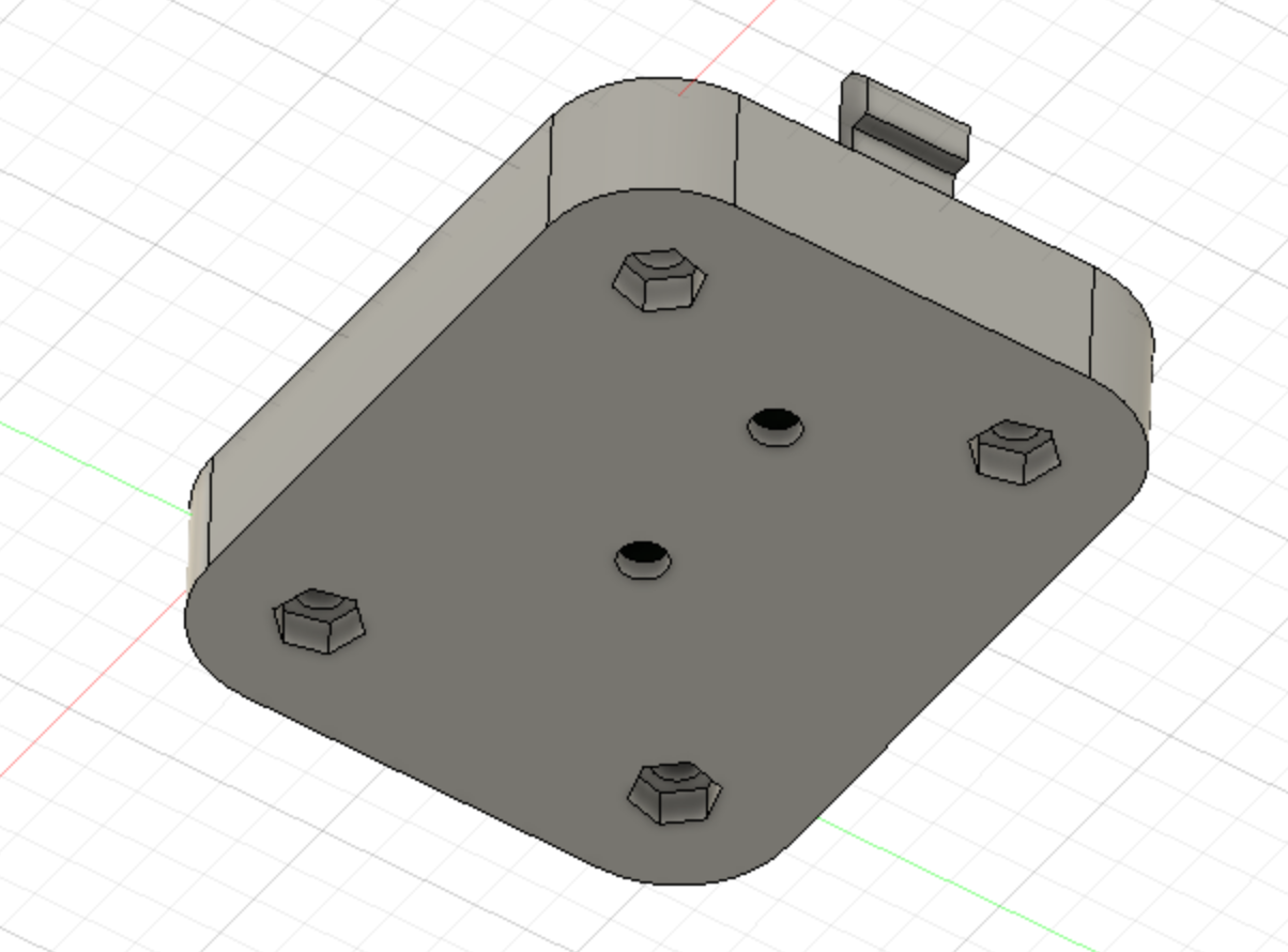
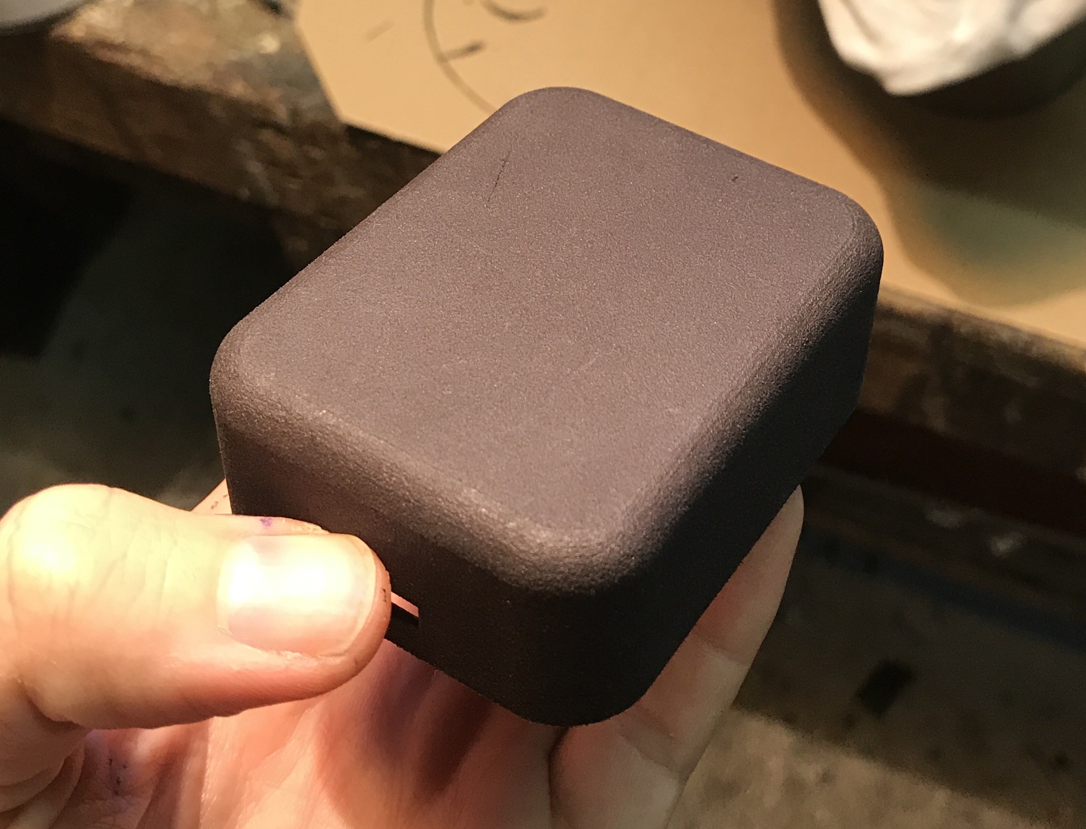
Enclosure and installation
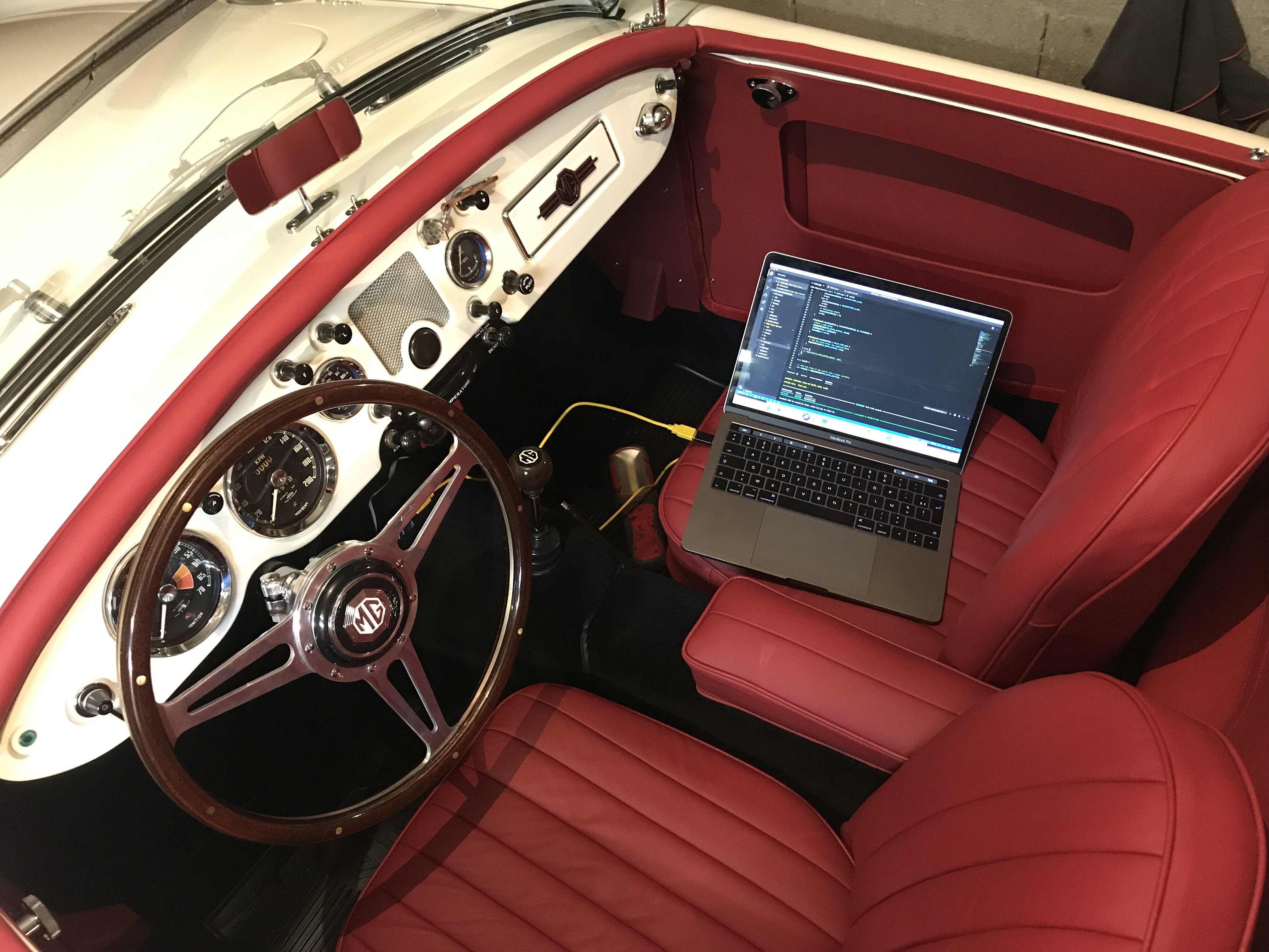
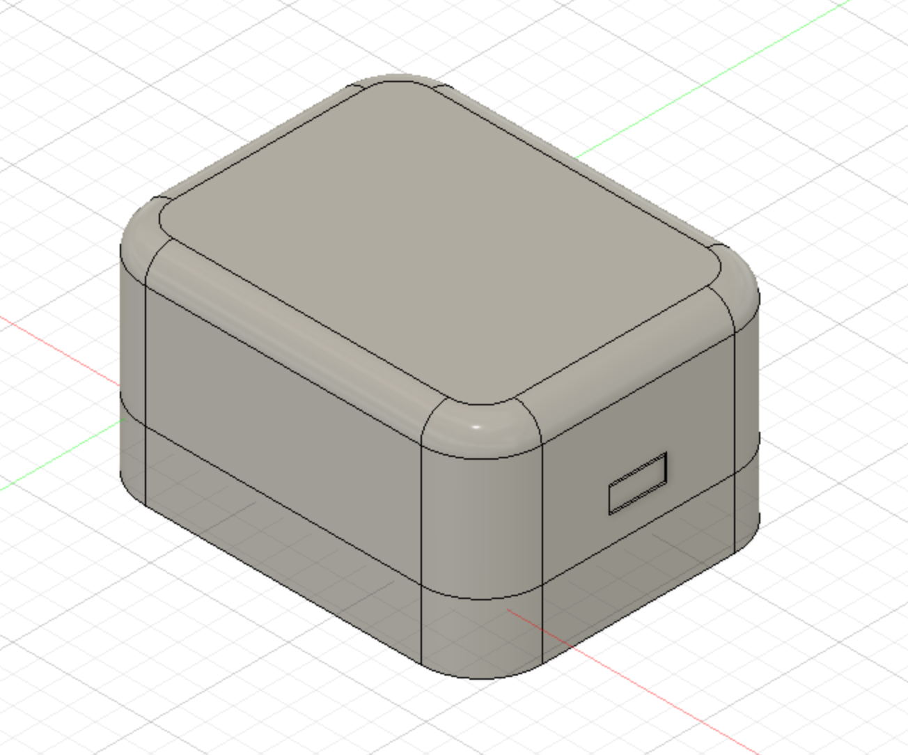
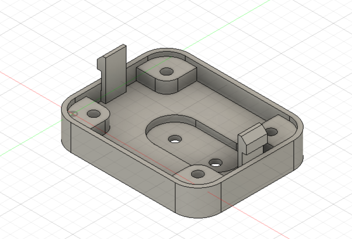
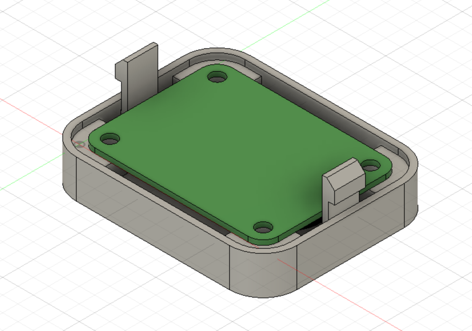
10/31/2020 at 11:29 • 0 commentsFor the enclosure I designed it in Fusion 360 with plans to screw the thing on the wiper motor itself (hence the 2 holes for the screws on the wiper motor housing). In the end, there is not enough access to fit it there and I put it under the dash. It's virtually invisible and keeps the stock look of the MGA (no extra components in the engine bay).
It's a two part, snap fit enclosure.
![]()
![]()
![]()
![]()
![]()
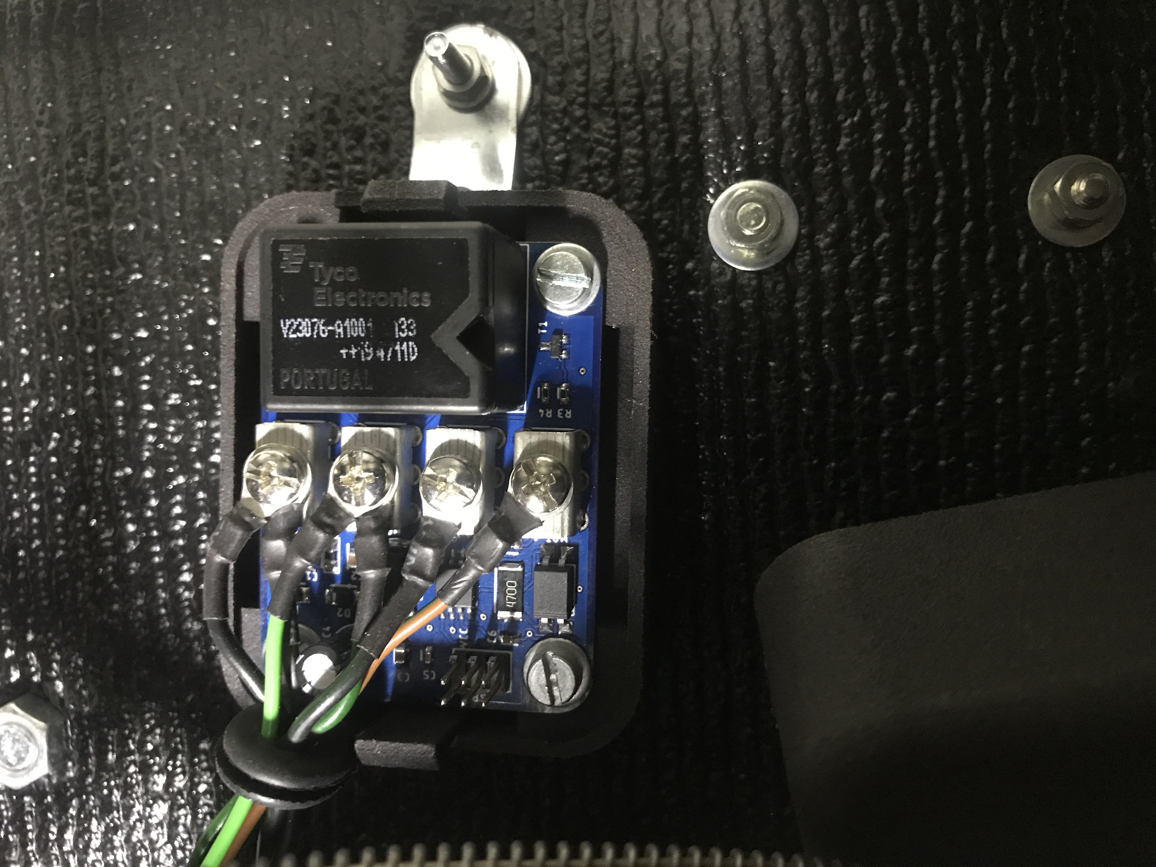
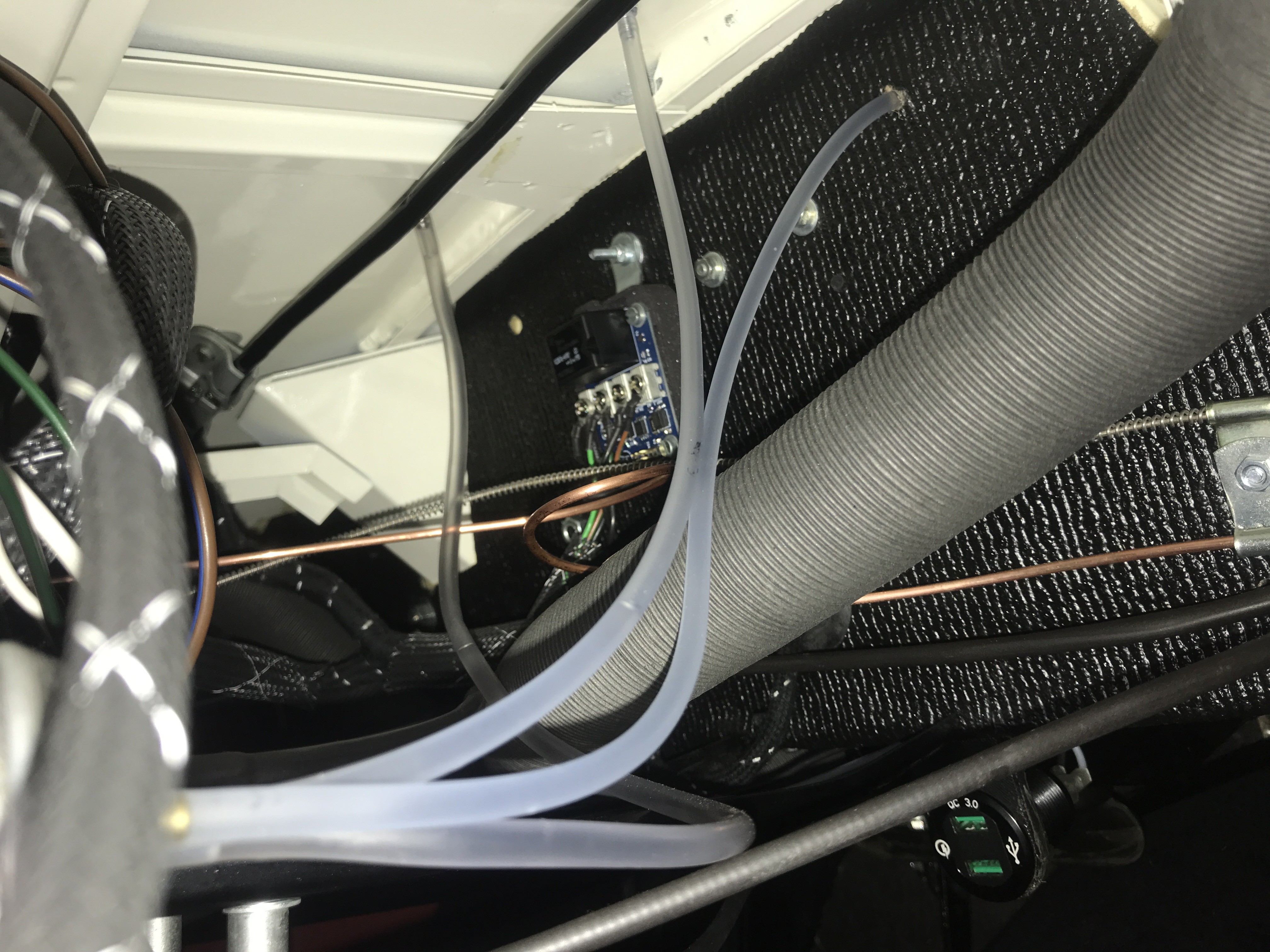
Fitted under the dash without the lid :
![]()
![]()
-
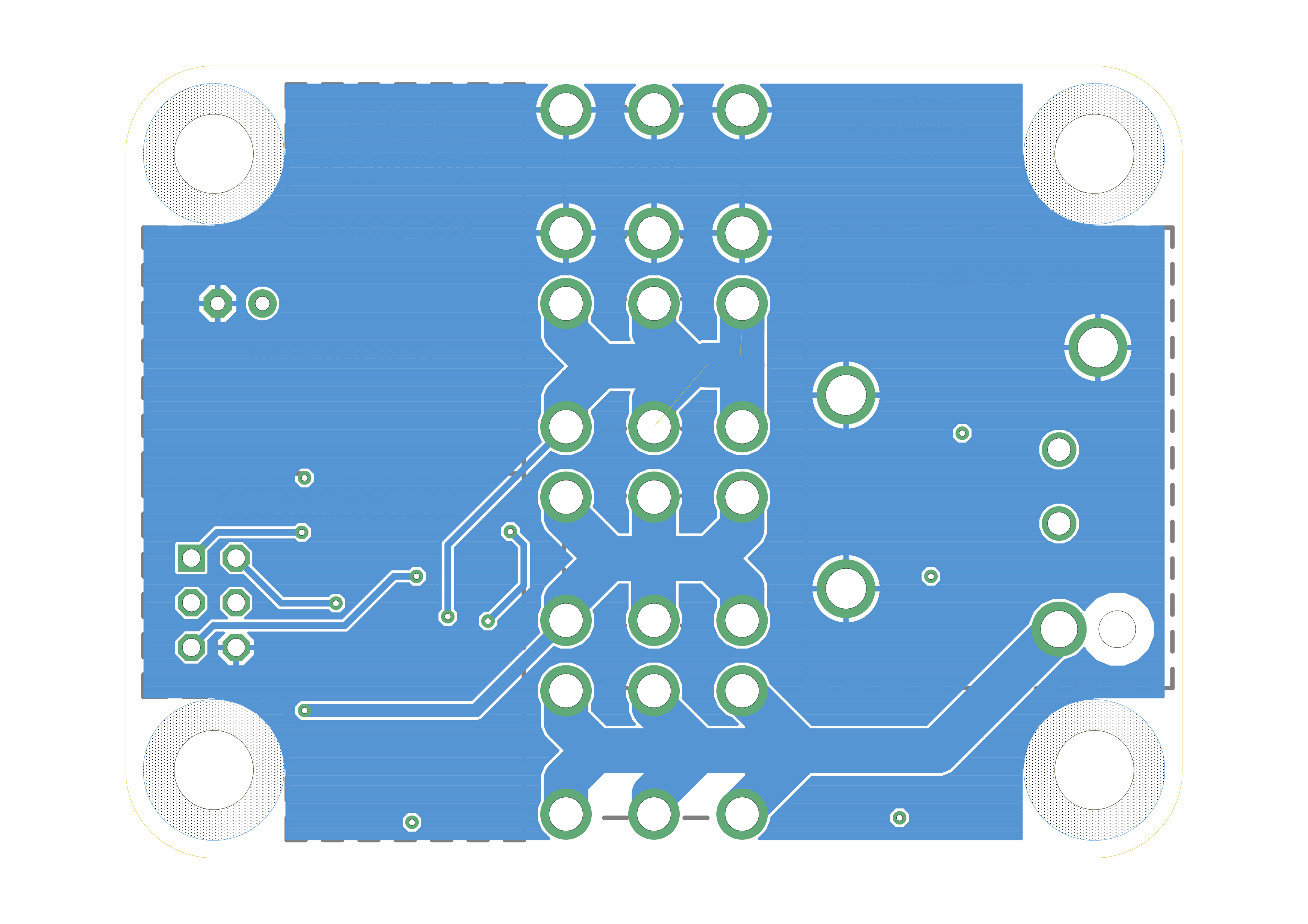
PCB board layout
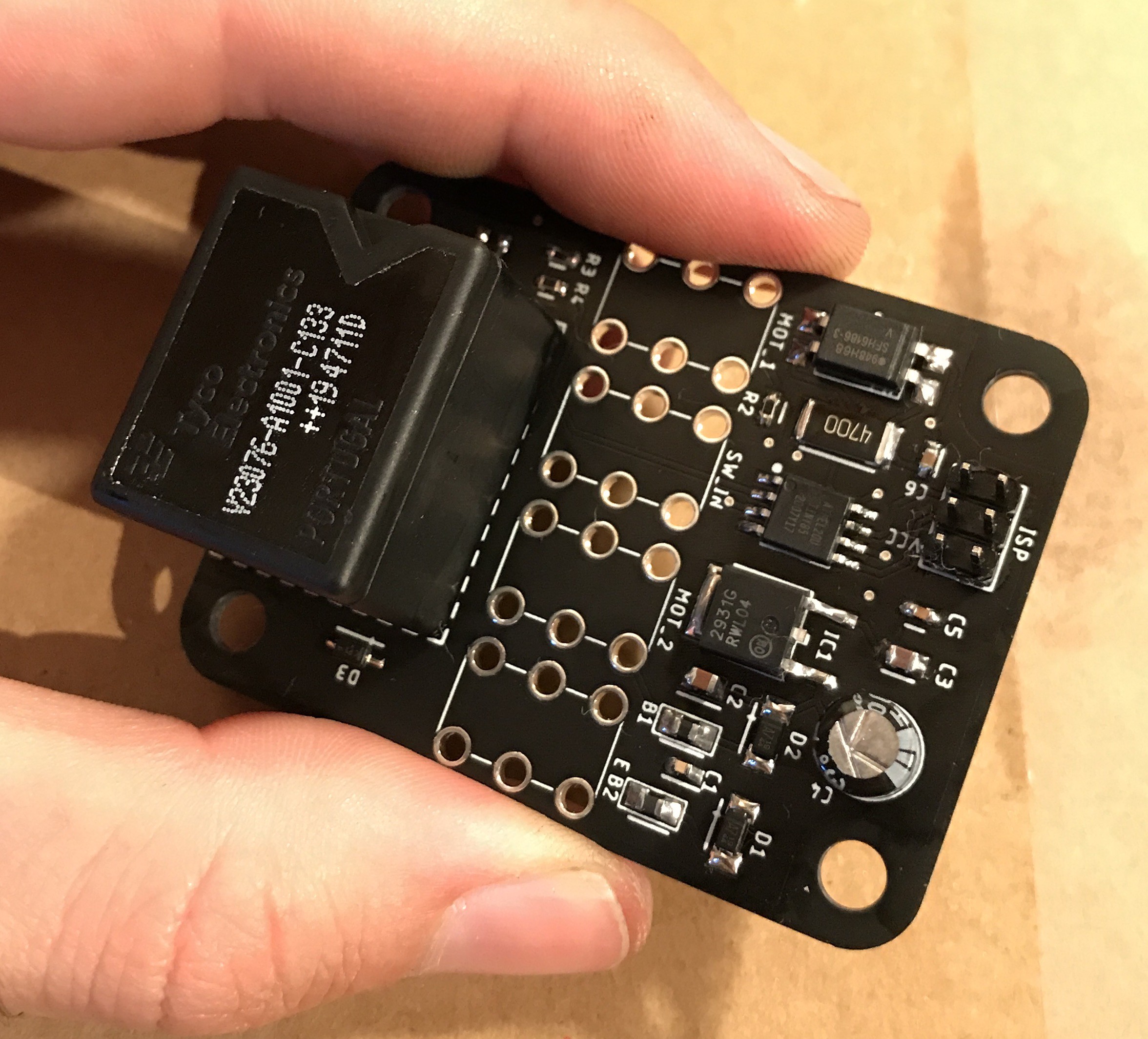
10/31/2020 at 10:28 • 0 commentsInitially I wanted to put the board in an enclosure not bigger than the wiper motor housing and screw or strap the controller to the wiper motor itself. Due to limited space in that area I went for SMD components where possible, and packed them all on a tiny PCB.
- TOP
![]()
- BOTTOM
![]()
Final Result :
![]()
![]()
-
Schematic and BOM
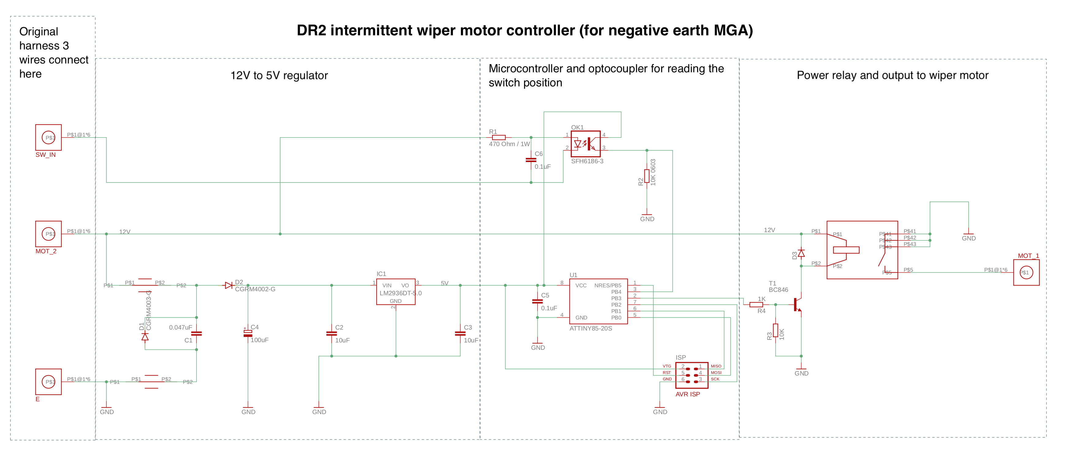
10/31/2020 at 09:15 • 0 commentsSchematic
Here is the schematic of the controller highlighting the three main parts : regulator, microcontroller and relay.
![]()
Bill of Materials
Part number Manufacturer Description Q U1 ATTINY85-20SU Microchip 8-bit Microcontrollers - MCU AVR 8K FLSH 512B EE 512B SRAM ADC 5V 1 IC1 LM2931DT-5.0G ON Semiconductor LDO Voltage Regulators 5V 100mA w/Load Dump 1 RL1 V23076A1001C133 TE Connectivity Automotive Relays Power Relay K 1 T1 BC846BLT1G ON Semiconductor Bipolar Transistors - BJT 100mA 80V NPN 1 OK1 SFH6186-3T Vishay Transistor Output Optocouplers Phototransistor Out Single CTR 100-200>#/td### 1 FB1, FB2 FBMJ2125HS420-T Taiyo Yuden Ferrite Beads HI CUR CHIP BD 0805 42OHMS 25>#/td### 2 D1, D2 CGRTS4007-HF Comchip Technology Rectifiers SMD 1000V 1A 2 D3 SZMMSZ33ET1G ON Semiconductor Zener Diodes REG 0.5W 33V SPCL 1 C1 C0603C473K3RACTU KEMET Multilayer Ceramic Capacitors MLCC - SMD/SMT 25V 0.047uF 0603 X7R 10>#/td### 1 C2 CGA4J1X7S1E106K125AC TDK Multilayer Ceramic Capacitors MLCC - SMD/SMT 0805 25VDC 10uF 10% AEC-Q200 1 C3 GRM21BC71C106KE11L Murata Multilayer Ceramic Capacitors MLCC - SMD/SMT 0805 10uF 16volts X7S 10>#/td### 1 C4 35ZLH100MEFC6.3X11 Rubycon Aluminium Electrolytic Capacitors - Radial Leaded LOW IMPEDANCE ELECTROLYTIC CAPACITORS 1 C5, C6 C0603C104K3RAC3190 KEMET Multilayer Ceramic Capacitors MLCC - SMD/SMT 25V 0.1uF X7R 0603 2 R1 CRGP2512F470R TE Connectivity Thick Film Resistors - SMD CRGP 2512 470R 1% SMD Resistor 1 R2, R3 ERJ-3EKF1002V Panasonic Thick Film Resistors - SMD 0603 10Kohms 1% AEC-Q200 2 R4 ERJ-3EKF1001V Panasonic Thick Film Resistors - SMD 0603 1Kohms 1% AEC-Q200 1 J1-J4 7799 Keystone Electronics Terminals M4 Screw term- H.D. 4 J5 10129381-906004BLF FCI / Amphenol Headers & Wire Housings ECONOSTIK HEADER DR VT TH 2X3 1 -
Controller requirements and basic function
10/31/2020 at 08:44 • 0 commentsI don't want to make any destructive or non-reversible modifications to my MGA, so the controller needs to be integrated in the current factory configuration (with the stock DR2 wiper motor).
Also I don't want to change the dash wiper switch to a multi position switch or anything non factory, so I need to make use of the stock ON-OFF switch to control the wipers state (ON or OFF) as well as frequency (intermittent delay).
The wiper motor may pull 5 to 10amp so the system needs to be able to sustain more than that, ie. using a power relay to drive the motor.
The solution I thought of was to use a microcontroller to read and interpret the wiper switch ON-OFF sequence to activate and change the frequency :
- Pull the switch to activate the wipers at their slowest intermittent settings (wiping every 10sec for exemple).
- Push then pull the switch quickly to go to the next intermittent settings (wiping every 5 seconds)
- Push then pull the switch quickly again to go to the next intermittent settings (wiping every 3 seconds)
- Push then pull the switch quickly again to go to the last setting ie. continuous wiping.
- ...
- At any moment, push the switch for more than 2 seconds to turn off the wipers and reset reset the system, next switch activation will start the wipers at their slowest intermittent settings as described above.
I decided to use the Attiny85 microcontroller as it is easy to program (Arduino framework compatible), has enough I/O pins for reading the switch position and send pulse to the relay, has a built-in clock, is cheap and readily available.
It works with 5V so I also need to have a 12v to 5v converter on the board.
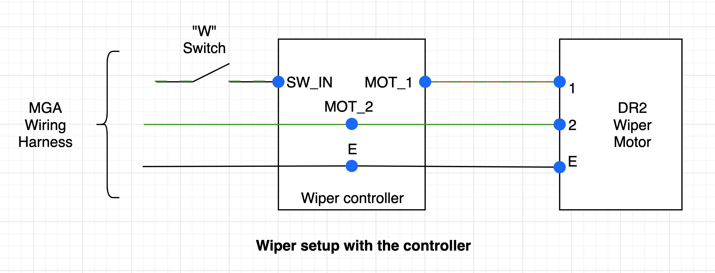
In short, the controller will sit right before the wiper motor, having the original 3 wires from the stock MGA harness connected to the controller, and 3 wires out from the controller to the wiper motor. The controller will have 3 main parts :
- 12V to 5V regulator
- Microcontroller
- Power relay
![]()
![]()
-
Single speed wipers not ideal
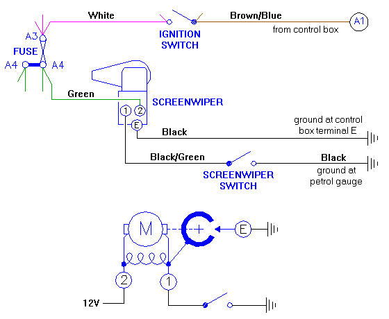
10/29/2020 at 07:57 • 0 commentsThe MGA is equipped with a Lucas DR2 wiper motor, as did some other British cars from the 1950s and 1960s, such as the Triumph TR2 and probably others. It's a single speed motor.
The wiper system is well described here, but here is the schematic of the factory configuration :
![]()
Wiper motor wiring schematic from MGAGuru
Notice the 3 terminals on the motor (1, 2 and E). Continuous +12V comes to terminal 2, then grounding the motor via the dash "W" screenwiper switch (on terminal 1) starts the motion of the motor, then the grounding is taken over via terminal E regardless of the position of the wiper switch until the wiper blades are back in their parked position. Then if the switch is still closed, the wiping continues, otherwise it stops until the switch is closed again by the driver.
When driving through light rain at moderate/slow speed, I find the continuous wiping motion to be too much, and I end up manually switching ON then OFF the wipers to get one wipe, then wait a few seconds, and switch ON then OFF the wipers again to get another wipe... etc.. In other words, I was manually making the wipers intermittent.
This project is about making a controller that simulates what I was manually doing, by switching ON-OFF the wipers at a given (and variable) frequency.
Classic car intermittent wiper motor controller
Reversible, no extra switch, multiple frequencies delay module for classic British cars.