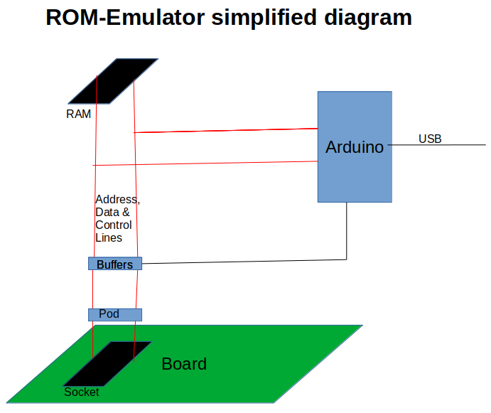
Here a diagram showing how the ROM-Emulator works. In operational mode, the RAM chip is connected through the buffers and POD converter to the socket of the target board. All the Arduino pins connected to the RAM are tri-stated, so the processor on the board sees the contents of the RAM.
When the Arduino accesses the RAM, the buffers are tri-stated, isolating the RAM from the board. The processor would see FFh in the memory region addressed by the socket. The Arduino can now fill the RAM with data received from the PC, or change it with its internal commands.
 fjkraan
Discussions
Become a Hackaday.io Member
Create an account to leave a comment. Already have an account? Log In.