GitHub Repository Link
Mechanical Design
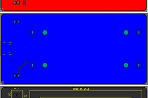
I have an old (defunct of course) battery pack, so I traced the profile onto graph paper and replicated in Visio. I added a slot for a PCB at the appropriate height (to put the PCB contact pads at the same position as the terminals of the pack). Exported to SVG and sent off to Ponoko for fabrication in 3mm thick fiberboard.
Charging Circuit (V1 and V2)
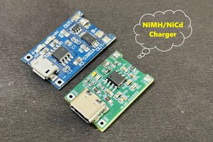
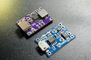
The MCP73831 does all the heavy lifting here - it's a completely integrated Lithium charge controller, handles the transition from CC to CV, and terminates charge when it's time. The schematic is lifted right from the datasheet application circuit.
Protection Circuit (V2)
In version 2, I added a Charger Immunity protection circuit, to avoid mayhem in the event that an HP AC adapter is connected while the LiPo pack is installed in the calculator. I used a very nifty 'ideal diode' from Maxim, the MAX40203, which integrates a P-channel MOSFET and the control circuitry to manage the gate, only turning it on (pulling to ground) when current is flowing in one direction. To make it compatible with the HP AC adapter's charge output (which is approx 50mA current source, open circuit voltage is >12VDC) I also included a 5.1V Zener clamp, to limit the voltage on the charger side to something below the 6VDC that the MAX40203 allows.
There are two "solder bridge" jumpers in the V2 design. JP1 is simply a 'bypass' around the MAX40203 IC, in the event it isn't needed (or doesn't work out). When shorted, it connects the LiPo + to the POS contact pad on the PCB. JP2 is a means to pull the MAX40203 "EN" (enable) pin high. EN allows the load side to be disconnected from the source (when pulled low) and of course, we always want the diode enabled. The Maxim datasheet says that the EN pin has an internal pullup and can float, but my simulation runs seem to indicate that it sometimes needed to be pulled high in order to work. So just wire it high on the PCB, right? Not so fast; my simulation also seemed to show a few mA current draw from the battery when the HP AC charger was present. So, I leave it as a solder bridge option and I'll sort it out when I get the PCBs.
Other Stuff
KiCAD for PCB and Schematic.
Visio (sorry!) for mechanization drawings and such.
Both V1 and V2 releases are tagged at the GitHub link.
 tomcircuit


 Sagar 001

 hesam.moshiri
 Bud Bennett
Love this design; inspired to try something similar. I like your care to use the ENIG finish, and the MAX40200 is a great find for this application!
Saw this article where the author used a regulator to (counterintuitively) squeak out some more battery life / reduce the dissipation in the calculator: https://www.edn.com/classic-hp-35-calculator-comes-back-to-life
Turns out, because the calculator's current input increases with increasing voltage, you can actually extend battery life by adding a (very low dropout) linear regulator - e.g. I calculated 3.6V with 30mV Vdo might give 4-5% longer run time than no regulator in my HP35.
Also, I thought I would try an arrangement to allow charging in-place with the HP charger. Not yet proven / tested that part but feel free to follow along: https://github.com/grob6000/hpbattery