Background Story
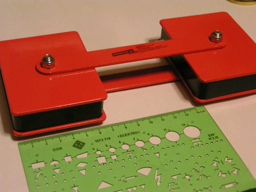
I wanted to measure the magnetic field B of this permanent magnet, to see if it's strong enough to use for DYI NMR (Nuclear Magnetic Resonance).
Theory
The idea was that most of the magnetic field lines are concentrated between the two iron spacers that link the two magnets together. If a probe is placed between the two spacers, the probe will feel most of the B. If the probe is removed (ideally to an infinite distance) the magnetic field seen by the probe will be zero.
If our probe is a coil, some voltage will be generated while pulling it out from the B magnetic field.
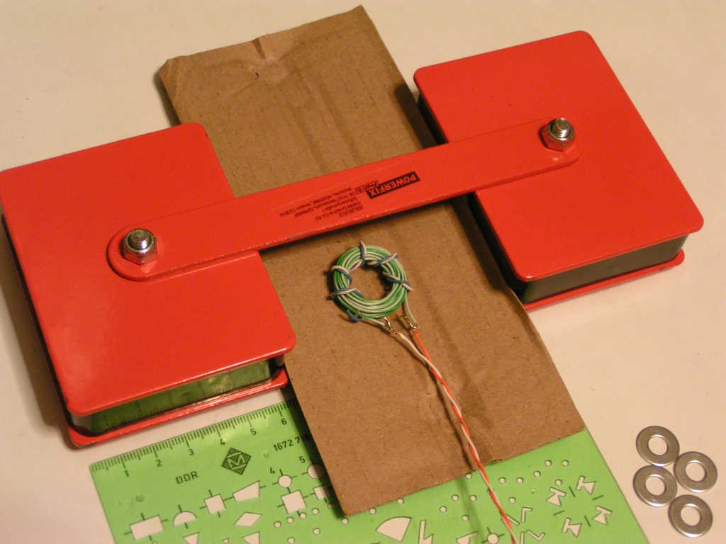
The coil has 17 turns made out of solid Cu wire from a former LAN cable. The blue white wire on the exterior is unconnected, just for mechanical consolidation of the whole donut. The coil is initially put in the middle of the two iron spacers, then the orange wire is slapped down over the edge of the table in order to quickly move the coil outside the iron spacers and thus to a zero B field.
From Faraday's induction law, the induced voltage V in an N turns coil will be:
where Φ is the magnetic flux
B being the magnetic field and A being the area. Combining the two formulas,
If we integrate over the time required to pull the measuring coil out of the B magnetic field, we get
Bt∞ is B outside the two iron spacers, so zero
Bt0 is the magnetic field B between the two iron spacers, the value we try to find outIn conclusion,
If we look at the voltage waveform with an oscilloscope while extracting the coil probe out of our unknown B field, then the ∫Vdt term is nothing but the area of the voltage waveform seen on the oscilloscope.
According to the last formula for B, no mater the speed we pull the coil out from the field, and no matter the shape of the voltage waveform induced in the coil, the area seen on the oscilloscope should be about the same, because area is dictated by the initial magnetic field B, which is constant.
Practice
Rigol DS1054Z can calculate and display for us the area of a waveform (the integral). Let's check if the area indeed stays the same. The next 3 screen captures show 3 different measurements. In all 3 the area is almost the same, about 355 microvolt-seconds.
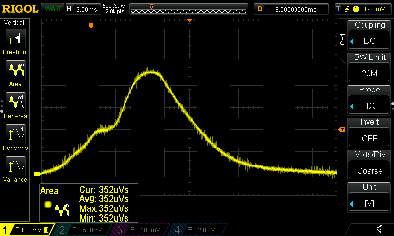
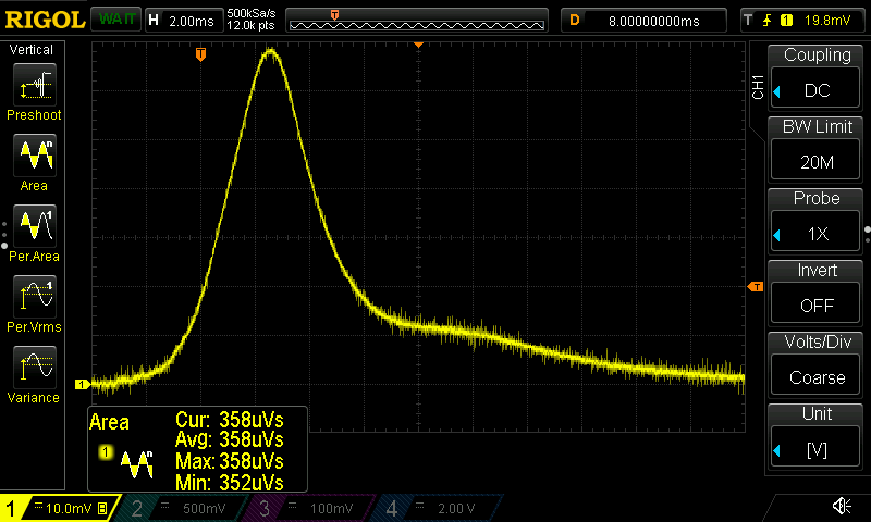
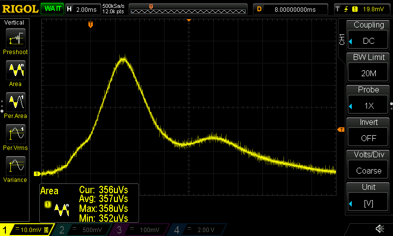
And constant area it is, indeed!
The shape of the induced voltage waveform differs for each measurement, yet the measured area is about the same, as predicted by theory.
At a closer look at the magnets, there is a washer between each of the two iron spacers and the magnets:

Let's remove the washers (in the hope that thus we can slightly increase the magnetic field) and measure again, 3 more times:
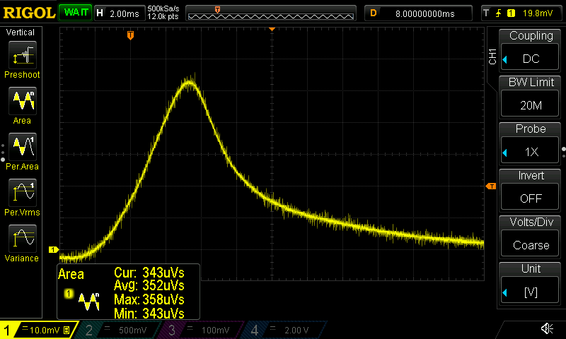
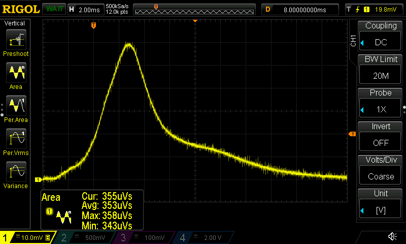

Strangely, the magnetic field seems to be slightly smaller without the washers, any ideas why?
Now, let's plug the numerical values into the last formula and see how many Tesla we have between the two iron spacers:
B = 1/(17 turns * 3.14 * 0.01 m * 0.01 m) * 355E-06 Vs = 0.066470 Tesla = 66.5mT
Not bad, 66.5 mT for 2 magnets bought for less than $10 from the LIDL supermarket.
If it were to use them for NMR (Nuclear Magnetic Resonance) experiments, the Larmor precessional frequency of 1H protons will be at about 2.83 MHz.
The magnet is pretty strong when used as intended, as a clamping device. Once clamped to a ferrous material it is almost impossible to remove with only one hand. It was sold as a "20Kg holding magnet" for keeping in place ferrous materials while welding or assembling them.
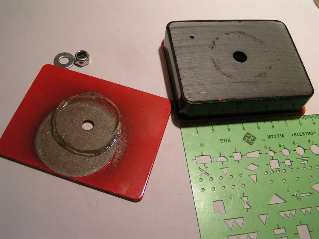
Just out of curiosity, the inside of the two magnets looks like this:
 RoGeorge

 Tom Meehan
 mircemk
 DeepSOIC
RoGeorge- Here's an idea for why removal of the washer weakens the B field between the straps:
If you trace the strength of the field for one of the magnet 'bricks' from the center of the larger face (call it the top face), across the top face toward (any) edge, around the side, and to the opposite (bottom) face center, the field will vary from the strongest at the top face center, weakening as you move away from the center and across the side face, to the weakest at the center of the side face (where it reverses polarity, say N to S), then increasing to equal and opposite polarity at the bottom face center.
When the straps are attached with washers, the strongest field is coupled into the straps at the center, and is then isolated (mostly) by the air gap between the strap and the top face, maintaining the value (more or less) it had at the center of the top face.
When the washer is removed, the field in the strap is 'shorted' ultimately to the weaker field at the top edge before leaving the magnet. What do you think?
Thinking about this further, how would the field between the straps vary if the bricks were oriented the same way vs. oriented in opposite polarities? Opposite would put the maximum flux inside the straps but cancelling in the gap between the straps (like in a toroid). Orienting them the same way (e.g. stop strap between N and N) would minimize flux in the straps, but increase it maximally between the straps.
This could be another cool demonstration of magnetic circuits using your innovative magnetic flux integrating tool! -Jim