Close
0%
0%

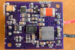
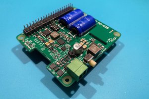
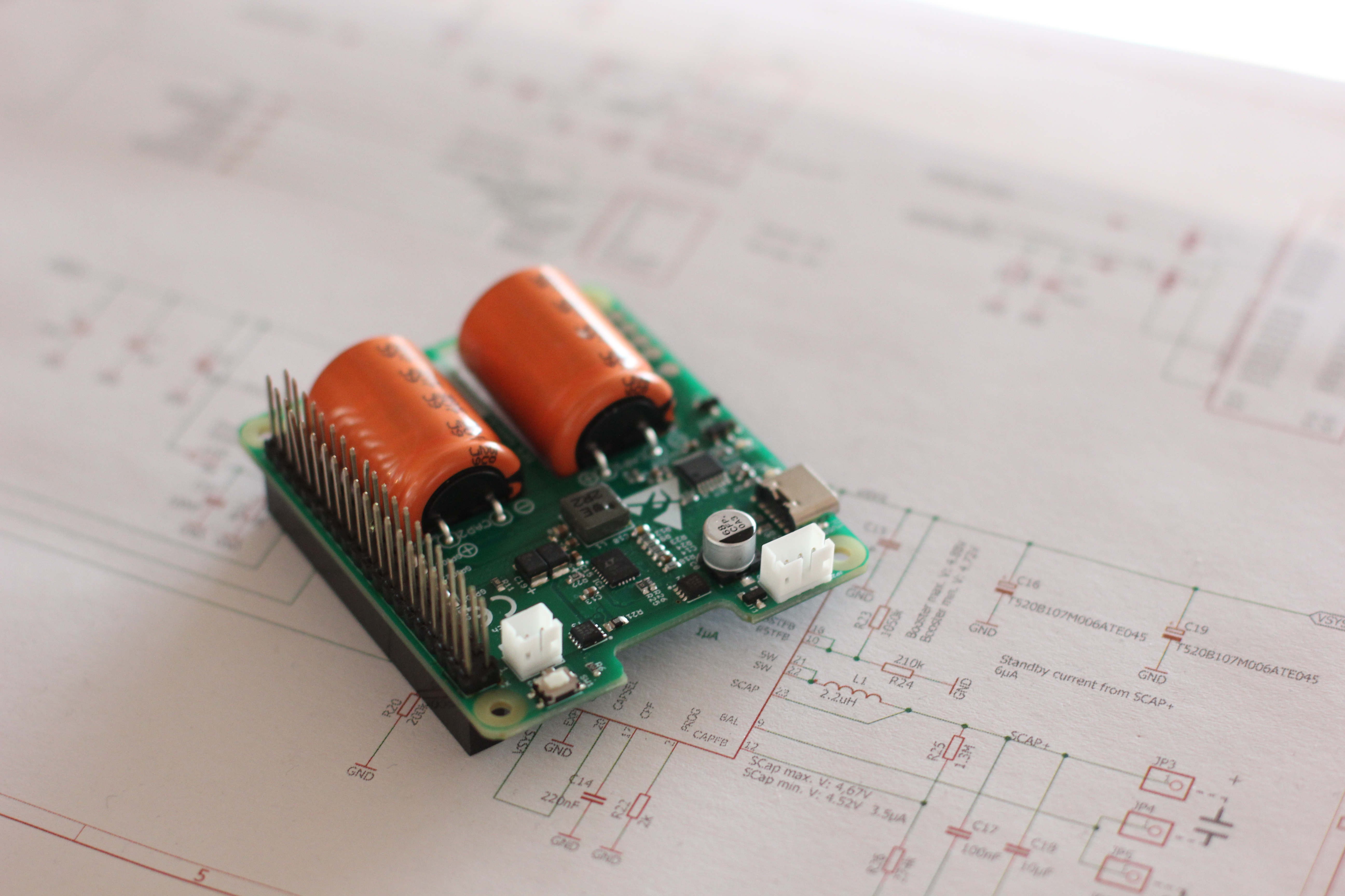
Raspberry Pi SuperCapacitor UPS with Power Switch

Powersupply for raspberry pi that includes an UPS, power button function and remembers its last state

Similar projects worth following
Starting from
$59.00
deichel has 84 orders / 8reviews
Ships from Germany
The inital idea was to build a powersupply for an arcade bartop that has a power button to switch the bartop (https://www.etsy.com/de/listing/663378240/8-bartop-arcade-cabinet-wood-kit-4-or-6) on and off. It should prevent from corrupted SD card files if the power cord is unintentionally removed during playing. So it must have an UPS feature. Especially children are not willing follow a "boring" shutdown procedure. If the power cord is removed the device should savely shutdown itself.With this electronics you don't have to care when and how you are switching off the Raspberry Pi. It will always take care of a save shutdown.SuperCapPi was born...

Feature List

  • Provide a stable powersupply with short time UPS function
  • Backup short power interruptions <2sec. without user notice
  • Mechanically stable USB-C powersupply connector instead of micro USB
  • Shutdown function using a power button
  • No maintenance cost caused by dead batteries
  • No risk of fire because the powersupply is using supercapacitors instead of using risky LiIon techology
  • Connector for external power button
  • Connector for an expansion board with relay & power LED to switch loads without draining current from the supercaps

Addon board with

  • External power LED
  • External relay option to switch high current loads

The UPS function is limited to an operation time of approx. 30..60 seconds. That is far enough for a save shutdown.

The powersupply remembers its last state. It excacly comes up in the last mode it was running.

That means:

  • If the device was disconnected by removing the power cord while it was on, it will restart in "on-mode" after reconnecting the power cord
  • If the device was off when removing the power cord it will remain off after reconnecting it and can be started using the power button
  • If it was switched off by the power button it must be switched on by the power button
  • If it was shut down by the shutdown command or via the user interface it will come up if the power button is pressed or the supply cord is (re-)connected

All those functions are available in a PIhat compatible PCB

Initially it was designed for arcade machines but there are a lot of usecases where it fits like:
Raspi based:

  • NAS
  • Homeserver
  • IoT server

I'm using it on all of my raspi computers at home because it is so convenient just to remove the power cord without the risk of corrupted SD-cards.

How it works

The design is based on the supercap charger LTC4041 from Linear Technology. I was following mainly the application note for that chip.

An additional µcontroller is taking care of the interface to the raspi and interacting with the LTC4041.

µController functions

Backup UPS funktion

This is not a really UPS backup power function. It is just to bridge small power outage glitches of < 2s.

Shutdown on power loss

The µcontroller is "listening" to the power fail output of the LTC4041. If it indicates a power fail. The µcontroller is waiting until the backup time of 2s is expired, then it gives notice to the raspi by pulling the power good signal low. After a period of approx. 25s it switches the supply to the raspi off.

Shutdown on button press

If the power button is pressed the µcontroller gives notice to the raspi by pulling the power good signal low. After a period of approx. 25s it switches the supply to the raspi off.

Shutdown using the Linux shutdown command

The raspi is pulling a specific GPIO (24 or 26) low. The µcontroller recognizes it and is switching the supply to the raspi after 25s off.

Remembering the last state

The state of the powersupply is recorded in the eePROM of the µcontroller. This means that after re-powering or pressing the power button it comes up in the same state as it was before switching off the power. A kind of wear leveling algorithm is used to ensure a lifetime of > 1 million switching cycles recoded in the eePROM.


DC Specification (For best performance use the official raspberry pi USB-C power supply)

Input Voltage5V .. 5.2V
Output Voltage (Power cord connected)same as input voltage
Output voltage during shutdown4.72V .. 4.88V
Output current (Power cord connected)limited by wall plug max. current
Supercapacitor charge current1A max.
Backup time (500mA load current, 25F Supercap)60s (theoretical vallue, load will be disconnected after 20s)
Backup time (1000mA load current, 25F Supercap)25s (theoretical vallue, load will be disconnected after 20s)

Performance (with 35F Supercaps)

Raspberry PI 3B with official TFT display powered by the official raspberry pi USB-C supply

Images showing the shutdown procedure
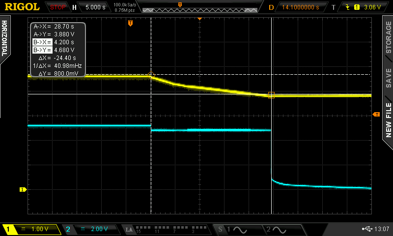
Channel 1 - Supercap...

Read more »
Raspi_SW.zip

Source files etc. to enable the shutdown acknowledge.

x-zip-compressed - 3.92 kB - 01/28/2021 at 20:07

Download

expansion_sch_bom.png

Expansion board with relay and power LED BOM embedded in schematics. https://oshpark.com/shared_projects/tU2LIOME

Portable Network Graphics (PNG) - 46.97 kB - 11/24/2020 at 11:41

Preview

SuperCapPi_11_sch.png

Schematics

Portable Network Graphics (PNG) - 33.74 kB - 11/18/2020 at 21:26

Preview

  • Nice article on the quality of commericial available USB power supplies and cables​

    D. E.05/25/2021 at 10:01 0 comments

    Similar results compared to my research:

    https://hyperglitch.com/articles/micro-usb-cable-for-power

  • Power supply issues user feedback

    D. E.05/23/2021 at 22:04 1 comment

    Today I got feedback of another user using a power supply other than the official raspberry pi USB-C PSU. In the end it did not work and from the failure description "My unit does not work with any of the USB-C power supplies I have; a short time after booting, the yellow LED starts blinking, indicating that the device has detected a voltage sag." it is clearly a PSU issue.

    So if you want to use it, use it with the official PSU. There is so much rubbish on the market and the official PSU isn't that expensive.

    I'm always interested in your experience with other brands of PSU. If you have one that works please post the barnd and its rating here.

  • Power Supply Nightmares again

    D. E.01/28/2021 at 21:06 0 comments

    I got feedback from some users that, depending on the load conditions powering up the Raspberry PI by connecting the USB connector sometimes is not working properly. I made several tests with different power supplys and finally I was able to reproduce the behavior.

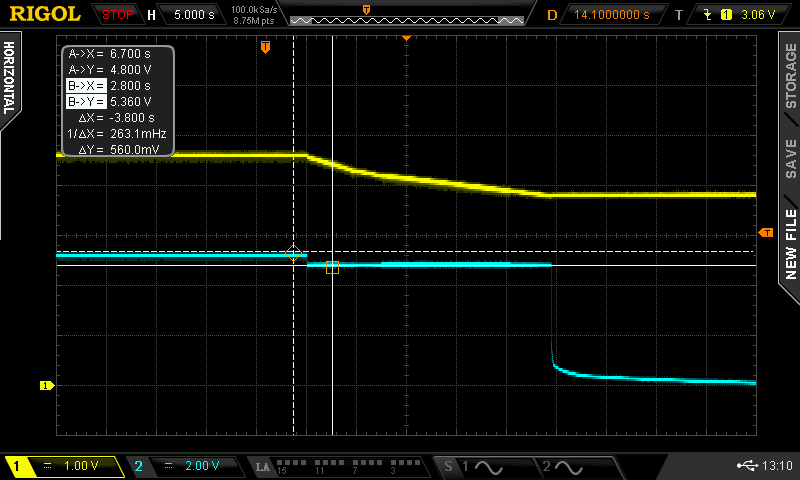
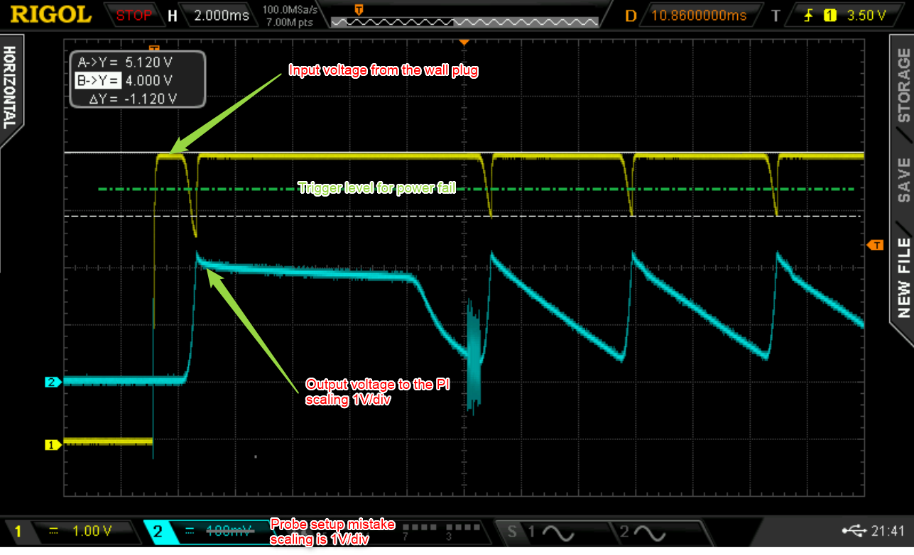
    The osciloscope view explains it best. Yellow is the voltage seen on the USB-C connector coming from the wall plug (scaling 1V/div). Blue is the voltage at the Raspberry PI pin 2 (+5V input) note the scaling is 1V/div. 

    What is happening here. The powersupply was connected and serves 5.1V. After approx 2ms the LTC4041 enables its DCDC to supply the Raspberry PI. In addition to that it also starts to charge the Supercapacitor with approc 1A of current. The output voltage to the PI is raising but the wall plug gets overloaded which results in a voltage drop below(!) the shutdown voltage limit of the PI. At this limit the LTC stops charging, the load current drawn from the wall plug is now reduced by 1A and it recovers. Then the voltage raises above the power fail limit and the story repeats and repeats and ...

    Only the usage of a good powersupply with enough internal blocking capacitors can avoid this kind of problems.

  • USB-C supply wiring

    D. E.12/14/2020 at 14:38 0 comments

    Survey on USB-C cables

    I checked several USB-C cables concerning voltage drop.

    I set my electronic load to 2A and switched the Supercap Pi USV on with charged capacitors.

    Keep in mind that if they are empty, the charge current of 1A adds to the 2A!

    This measurement again shows that the only good supply solution is to use the official Raspi 4 power supply.

    Cable TypelengthVoltage drop
    Orzly® Neue Zertifizierte USB 3.0 Kabel (Amazon)1m340mV
    Xaomi Mi9T pro cable1m610mV
    USB Typ C Kabel, RAVIAD (Amazon)0.5m420mV
    USB Typ C Kabel, RAVIAD (Amazon)3m650mV
    Official Raspberry Pi 4 USB-C supply1.5m-70mV (Voltage at USB-C connector
    of the Supercap Pi USV was 5.07V)

  • Replacement for the 35F Supercap

    D. E.11/24/2020 at 17:37 0 comments

    Perfect replacement for the 35F EATON Supercaps

    Vishay has automotive qualified supercaps with 30F capacity.

    AEC-Q200 Vishay 225 EDLC-R SuperCap, radial 30F -20 %, +50 % / 2.7V, Ø 18.5 Dia. x 27mm

    Lifetime 500000 cycles, >10 years at 20°C.

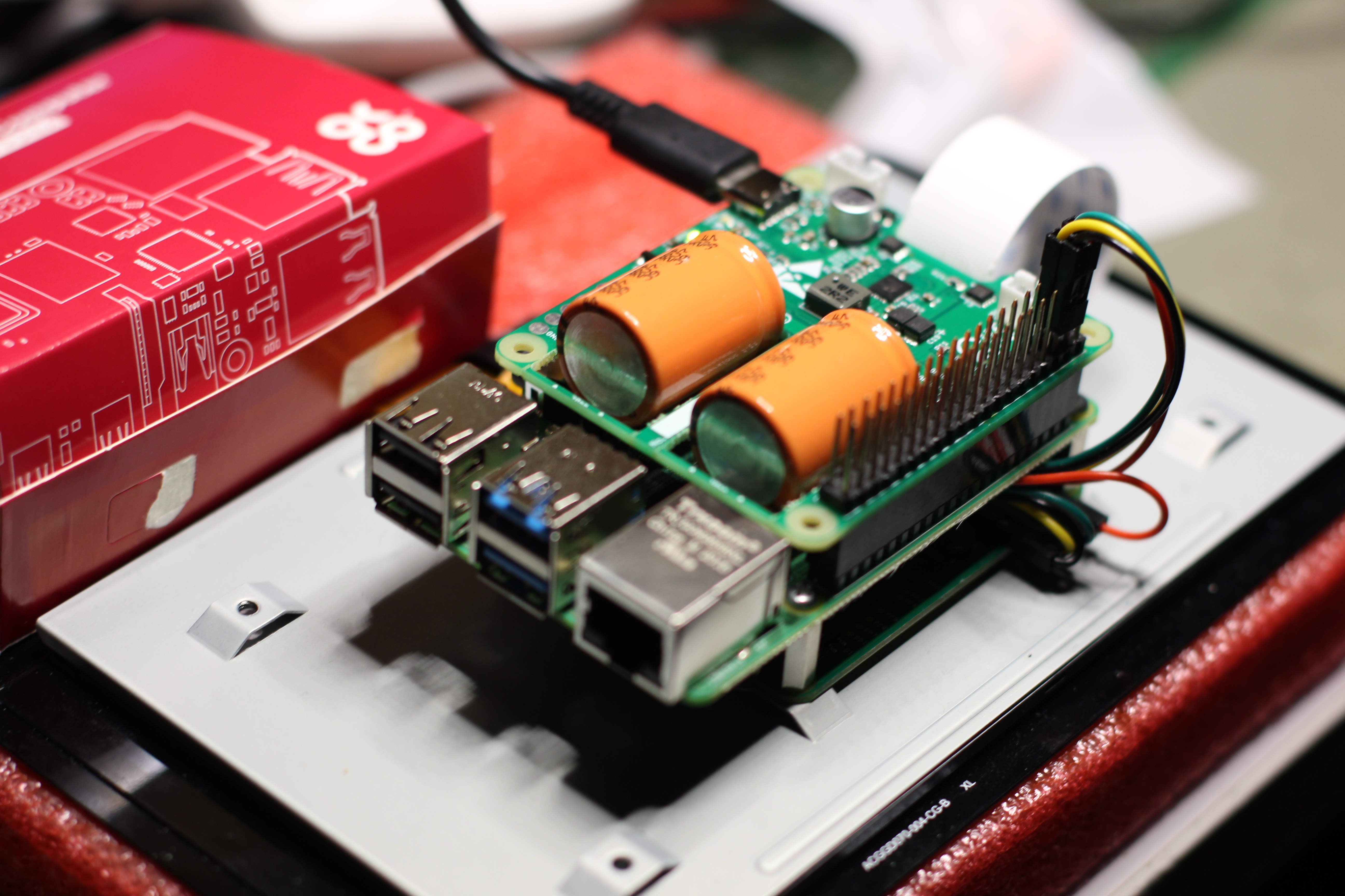
    They fit perfectly onto the board and do not interfere with LAN & USB of the Raspberry Pi.

  • Relay expansion board on OSHPARK

    D. E.11/24/2020 at 11:19 0 comments

    Relay expansion is available on OshPark for DIY

    https://oshpark.com/shared_projects/tU2LIOME

View all 6 project logs

Enjoy this project?

Share

Discussions

gio wrote 02/19/2021 at 14:43 point

Hi,

I just received and tried the UPS. It seems a very nice engineered product. Thank you.

However, I wanted to ask you what is the expected behaviour in the raspberry console when the power button is pressed or power cord is removed? 

I was expecting the typical raspberry poweroff and shutdown sequence messages printed to the console, but this does not happen. Nothing is displayed and the power is removed from Raspberry only after 22seconds, not 30..60.

I tried adding to /boot/config.txt the lines below individually or together

dtoverlay=gpio-poweroff  

dtoverlay=gpio-poweroff,gpiopin=22

but it does not work

I have a Raspberry 3B+ and the UPS is the version with 2 orange 30F SUPERCAP. I don't have any load attached.

It doesn't seem to perform the safe poweroff  procedure...

What should I do?

  Are you sure? yes | no

D. E. wrote 02/19/2021 at 14:55 point

Hi !

All boards were tested before shipment so I'd assume that the shutdown signal is not correctly mapped.

How is the power good solderbridge (SJ2) configured?

The expected behavior is that after 2 sec. the power good signal goes LOW (the led on the UPS boards is blinking) and after ~20sec. the power is cutted.

The power good signal can be mapped to GPIO3 or GPIO22 by soldering the jumper.

You can check if the shutdown is working without the UPS board by connecting a wire between the +3,3V header (pin 1 of the PI connector) and GPIO3/GPIO22. After the PI finished booting, remove the wire. It should then perform a shutdown.

  Are you sure? yes | no

gio wrote 02/20/2021 at 09:02 point

Ok, it works correctly! 

I spent a lot of time to figure out why the gpio-poweroff wasn't working on the pi itself. Then I found out that there was a typo in the dtoverlay line.

Almost anywhere on the internet you can find the following line, which doesn't work with my RPI 3B+ and Raspbian Buster lite 2021-01-11:

dtoverlay=gpio-shutdown,gpiopin=22

while the following, adding underscore to gpio_pin,  does work:

dtoverlay=gpio-shutdown,gpio_pin=22

Thanks for your product, seems great for now!

  Are you sure? yes | no

D. E. wrote 12/28/2020 at 14:43 point

The tracking says that it left Frankfurt Airport on the 9th of december. So i'd assume that it already arrived in the US.

  Are you sure? yes | no

D. E. wrote 02/19/2021 at 14:56 point

Tracking shows that it has been delivered.

  Are you sure? yes | no

D. E. wrote 12/25/2020 at 15:46 point

All Orders are shipped, latest 3 days after I received the order. All orders have a tracking number. Your order was posted on 8. December at my local postoffice.

  Are you sure? yes | no

Similar Projects

Does this project spark your interest?

Become a member to follow this project and never miss any updates