After creating the design, I ordered prototype PCBs and stencil from JLCPCB. This log documents the build of three prototypes.
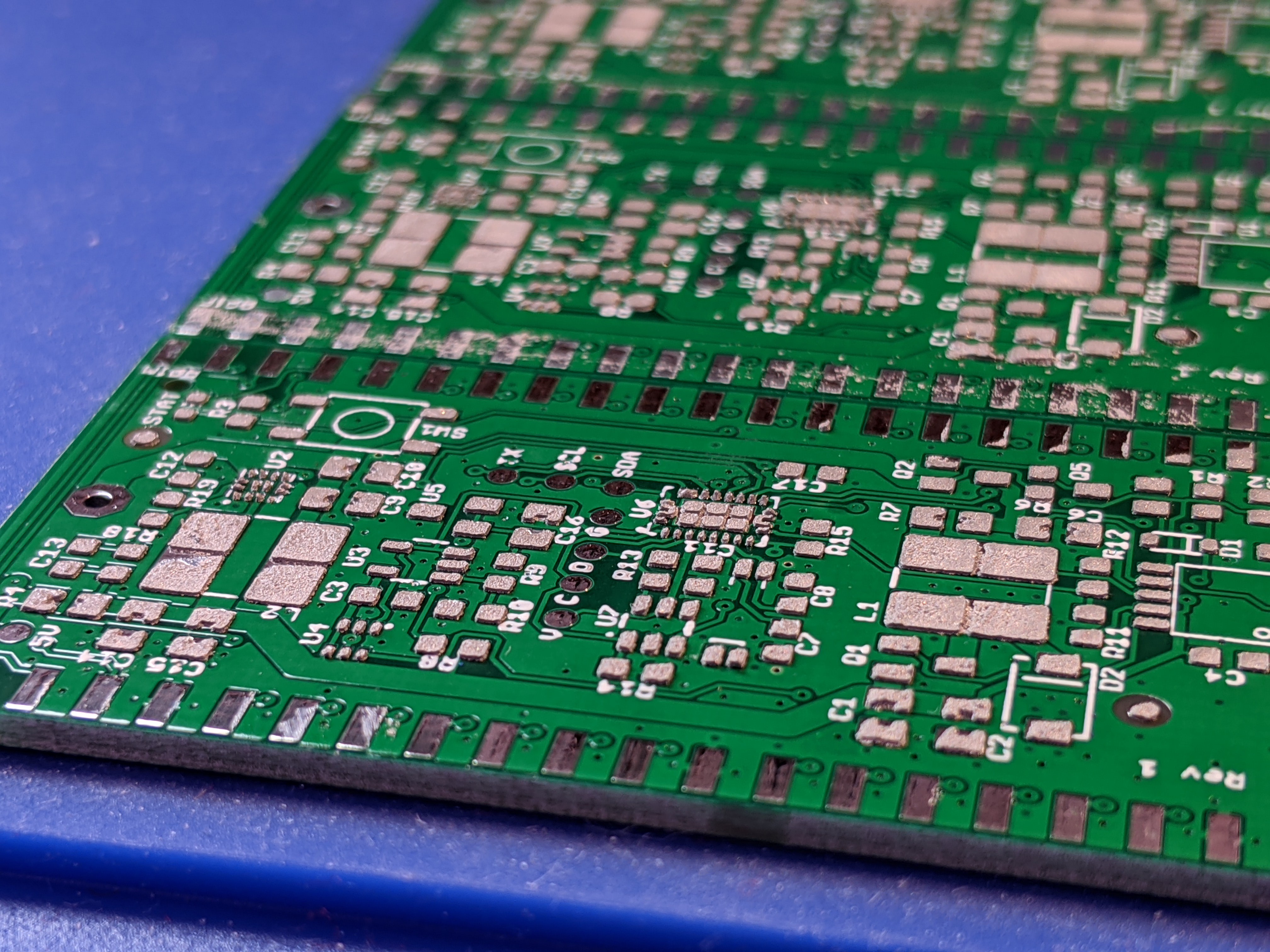
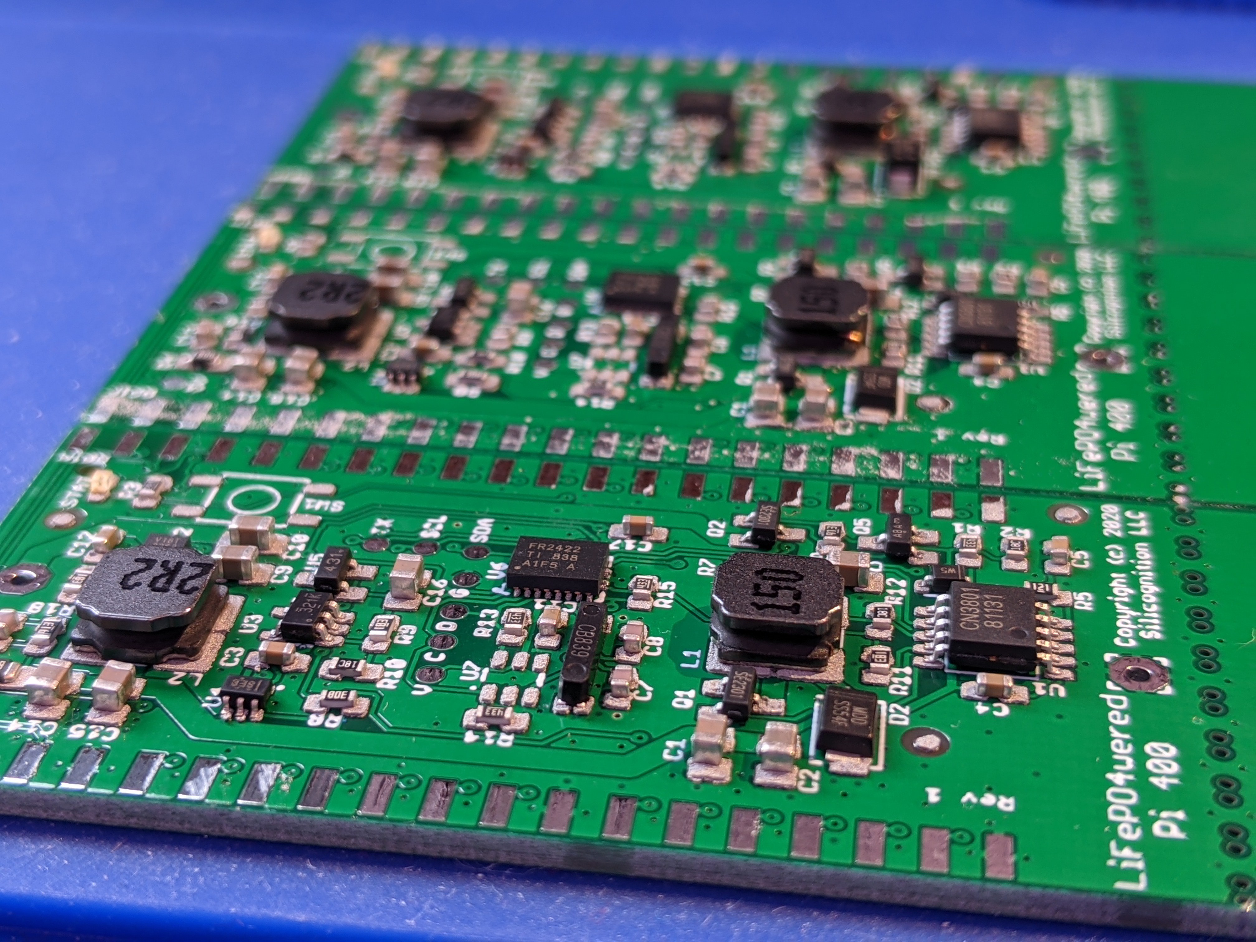
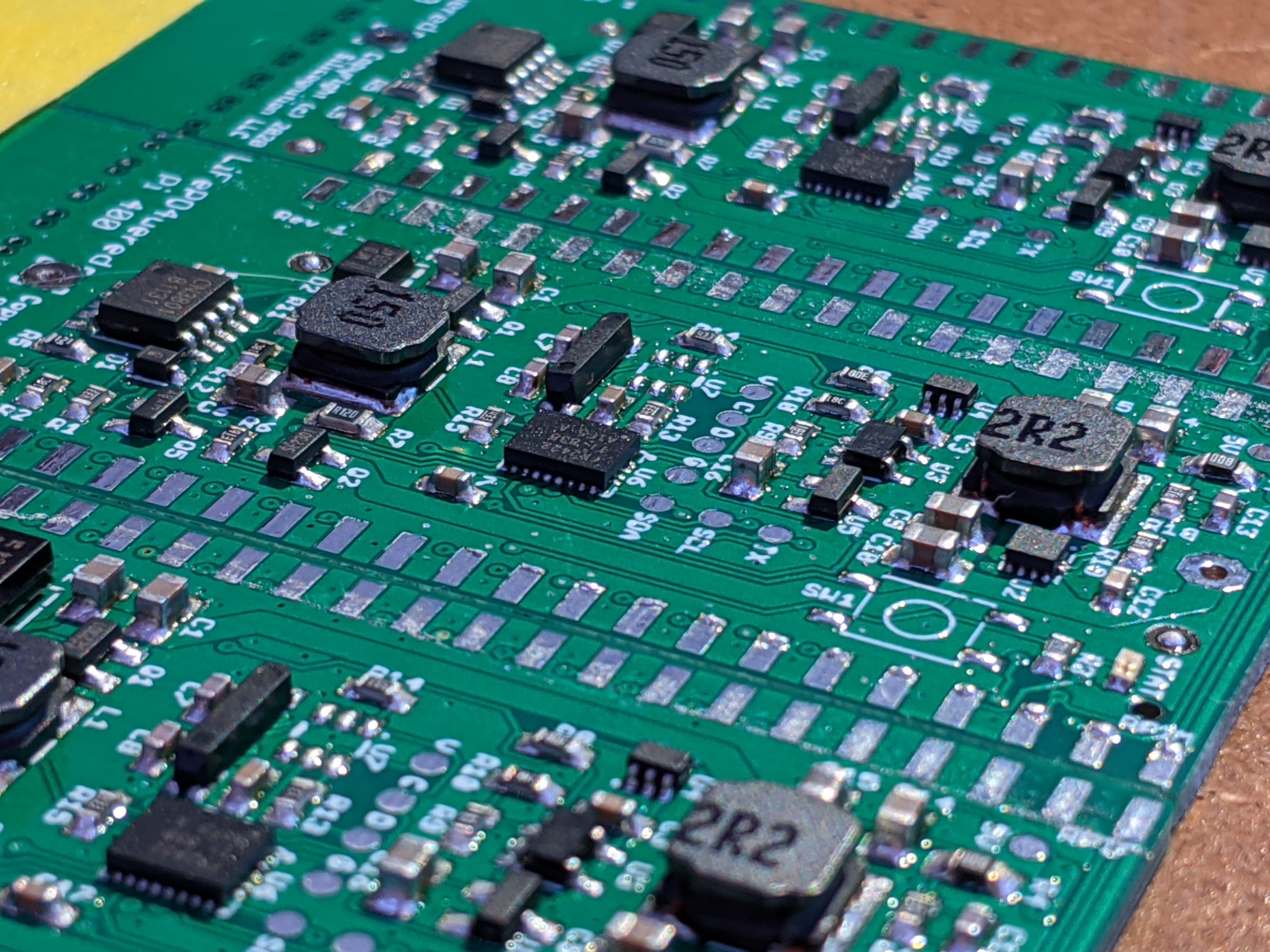
The SMT part of the build went very smoothly. No obvious shorts I needed to deal with. Two parts are still missing: the button (SW1 which didn't arrive yet and I'll add later) and there's a footprint for a low cost 6-pin Padauk micro (U7) which will be used to enable firmware update of the MSP430 over I2C BSL. No point in mounting an OTP micro until I've figured out its programming. :)
After such a smooth SMT build, connecting the headers unexpectedly was a whole lot more troublesome:
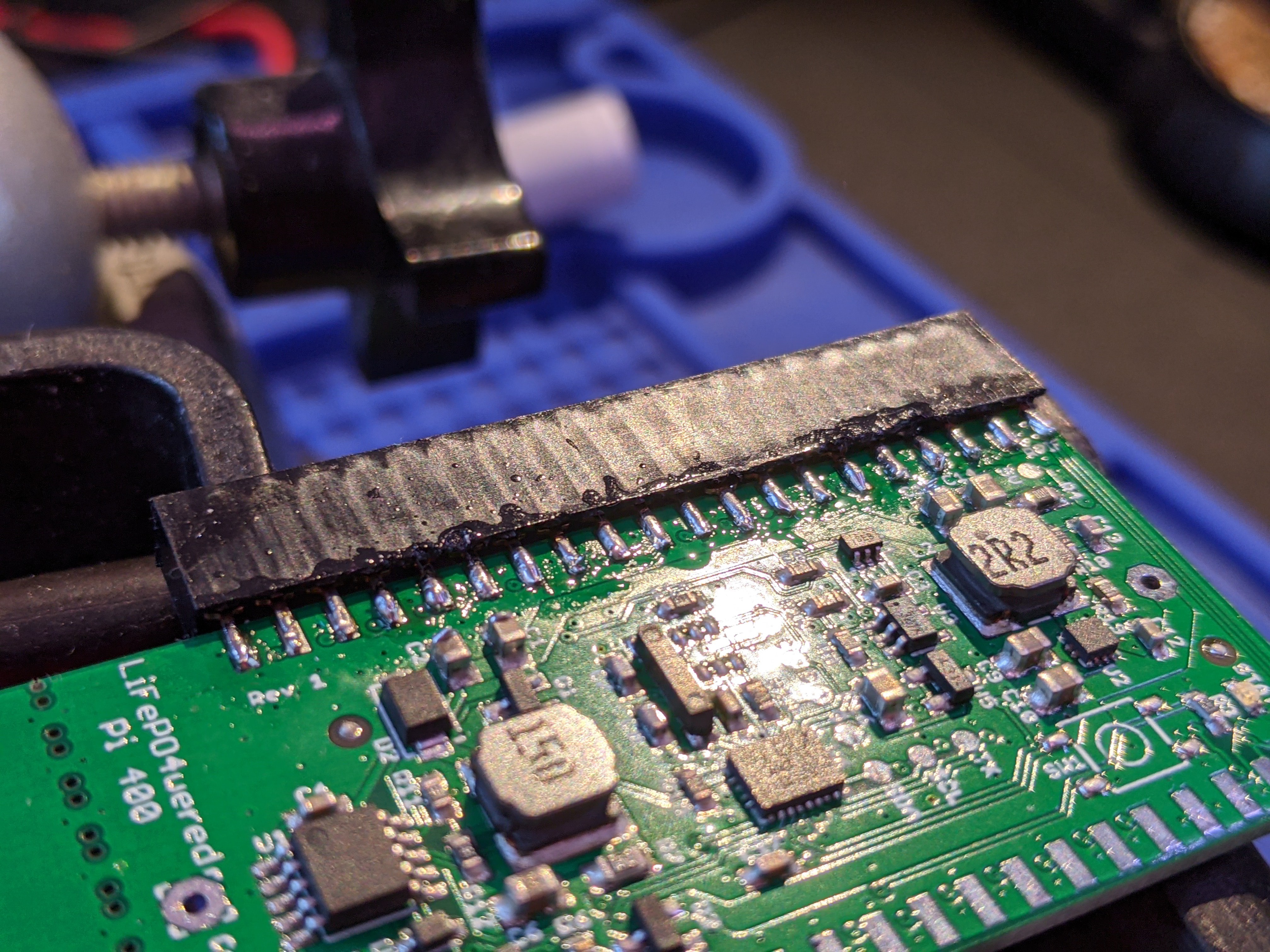
Ugly, I know. I had a lot of trouble getting both the pads and pins to wet and connect. In hindsight, the pads are too small as they are completely under the pin so they're hard to heat together with the pin. Also, the board is thinner than the spacing between the two rows of pins, so there's a gap that needs to be bridged. I'll have to investigate thicker PCB options for a better fit.
I got a prototype together in the end:
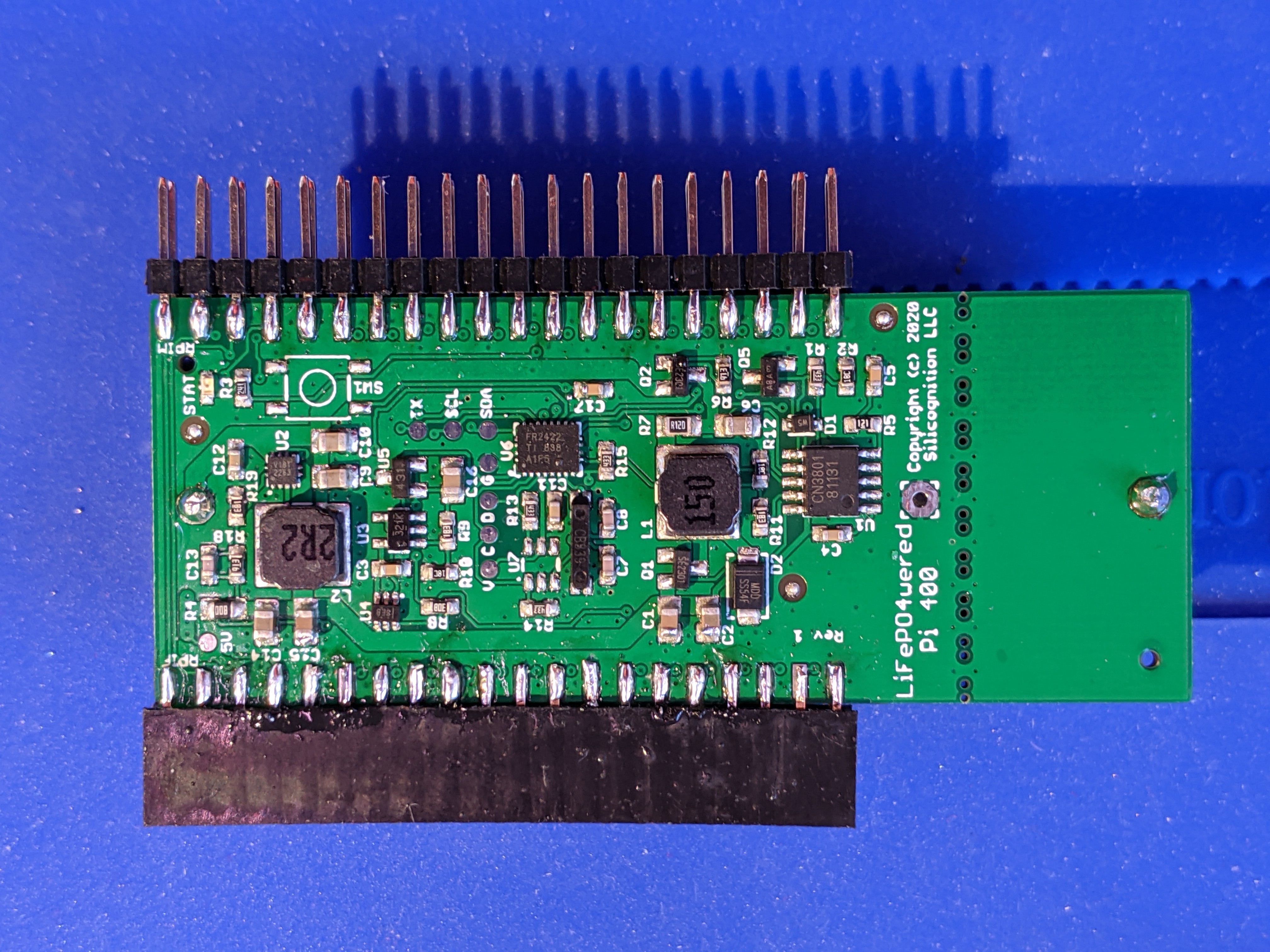
The battery holder for an 18650 LiFePO4 is on the bottom of the board. I was able to confirm some basic functionality:
- I could connect to the MSP430 microcontroller using the MSP430-FET.
- I could enable the 32 kHz crystal oscillator for system clock generation and RTC timekeeping.
- The battery would charge when external power was connected and charging enabled.
- The boost converter would generate ~4.85V when enabled (I did not test current capability yet).
- The boost converter could be enabled while external power was applied and nothing would blow up! The boost converter would simply stop switching with the voltage above its setpoint, and start up as the voltage would start to drop when external power was removed.
This last test was really important, the whole concept of this UPS would stand or fall with the result of this test. And as far as I could tell, it passed with flying colors! I could have the boost converter enabled and apply and remove external power at will, the boost converter would just take over when external power went away and stop providing power when external power came back. You could see the voltage on the scope go from 5V to 4.85V and back to 5V and the whole thing would be completely glitch-free!
Next things to test:
- Output current capability.
- ADC measurements of system and battery voltage.
- ADC measurement of input/output current, and the accompanying detection of whether we're supplying power or external power is present.
Once these are confirmed, I can start writing the firmware for this new micro. It's still an MSP430 like in the #LiFePO4wered/Pi+, but this is a newer generation device with FRAM and enhanced peripherals compared to the part I used in previous designs, so some porting will be necessary.
 Patrick Van Oosterwijck
Discussions
Become a Hackaday.io Member
Create an account to leave a comment. Already have an account? Log In.