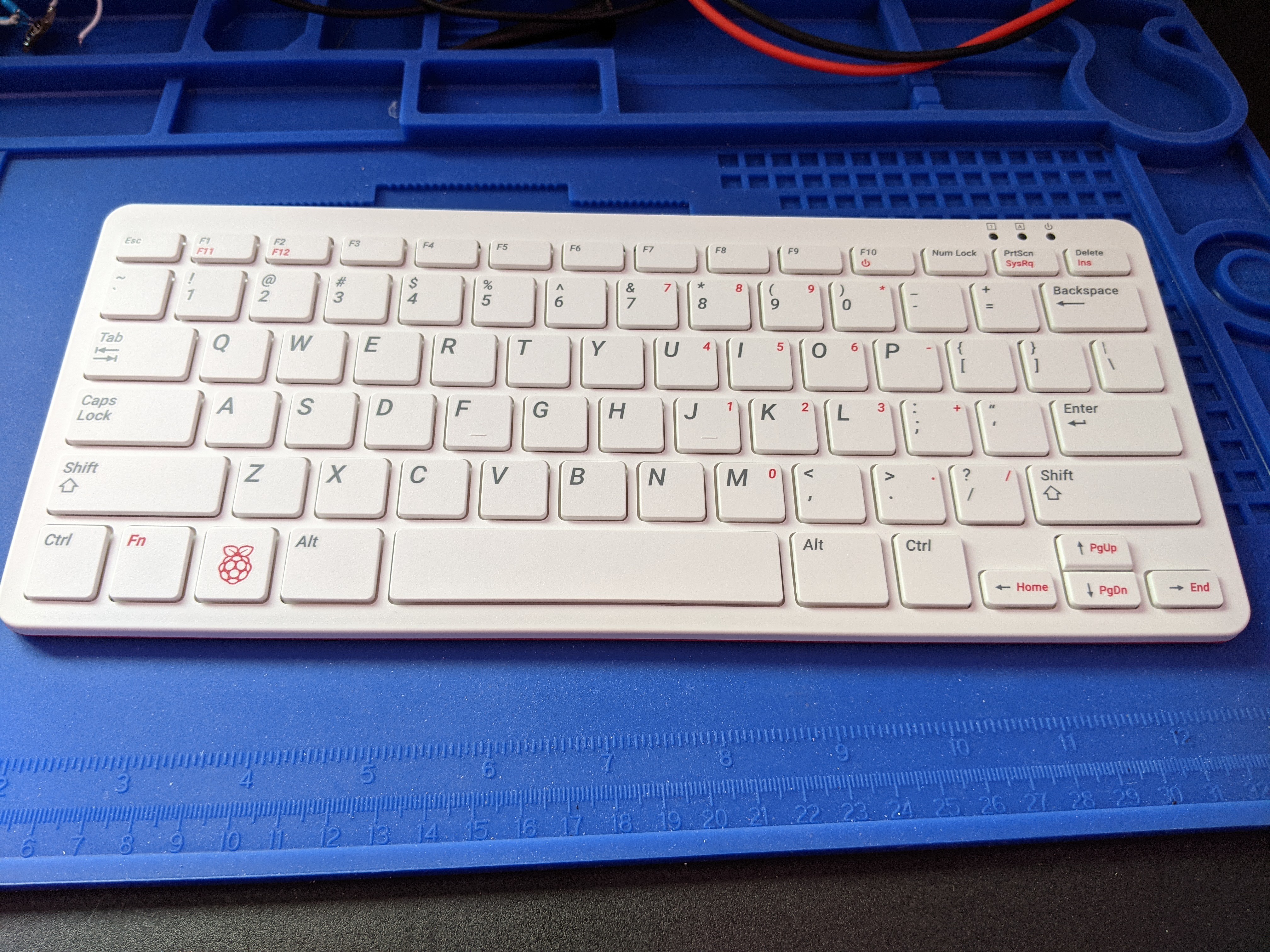
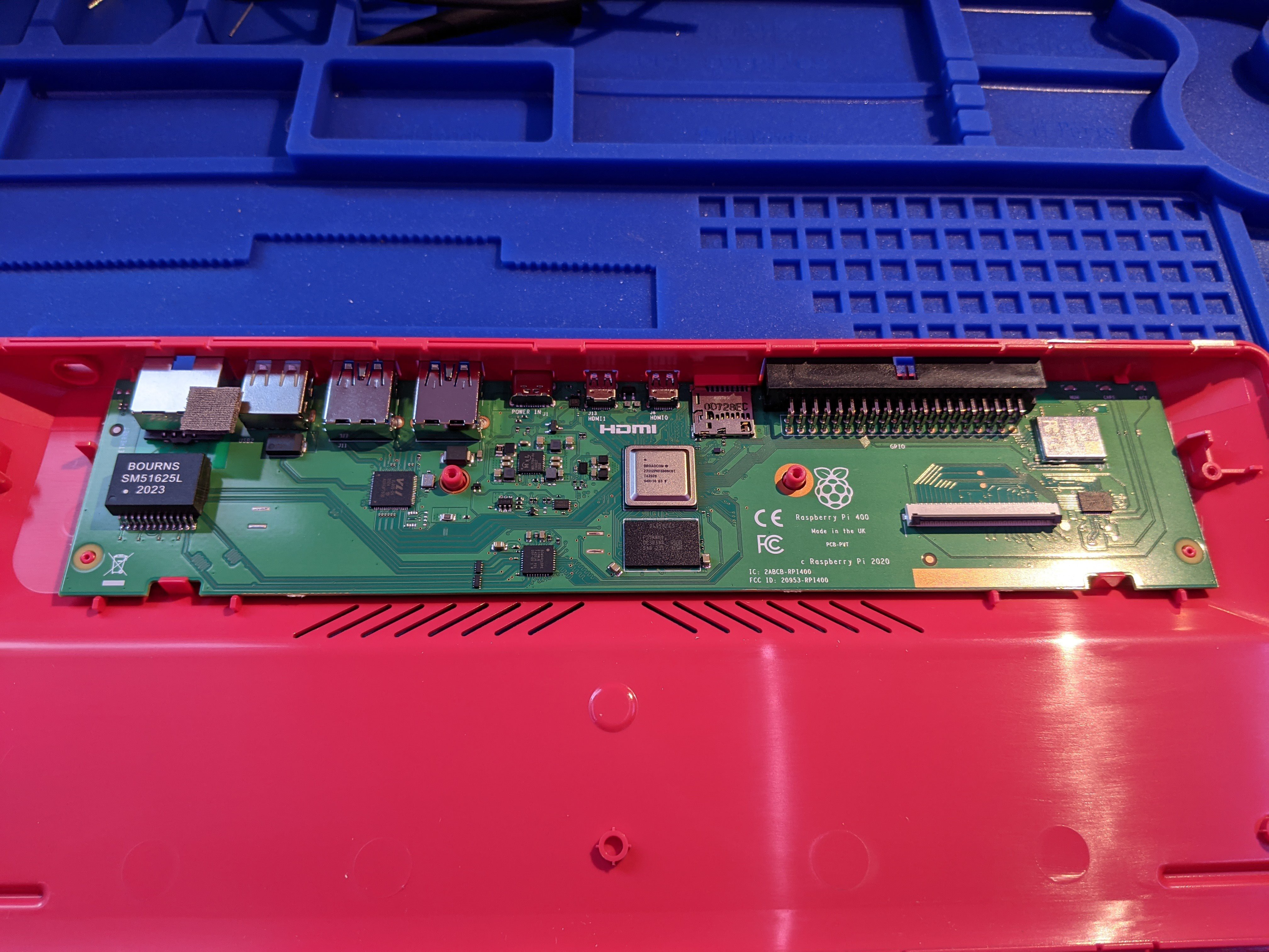
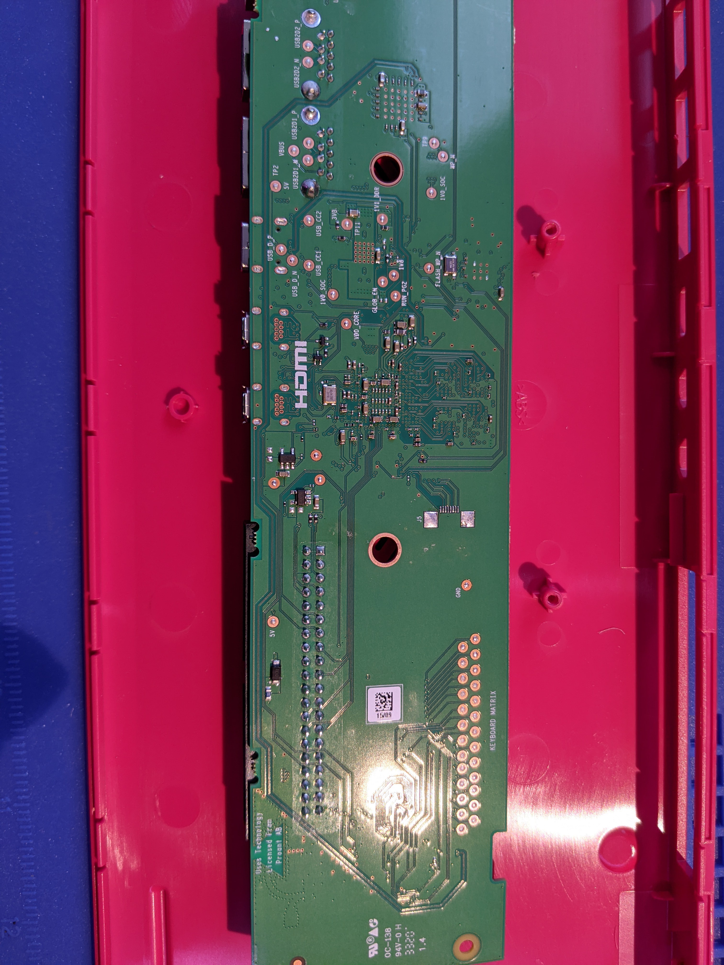
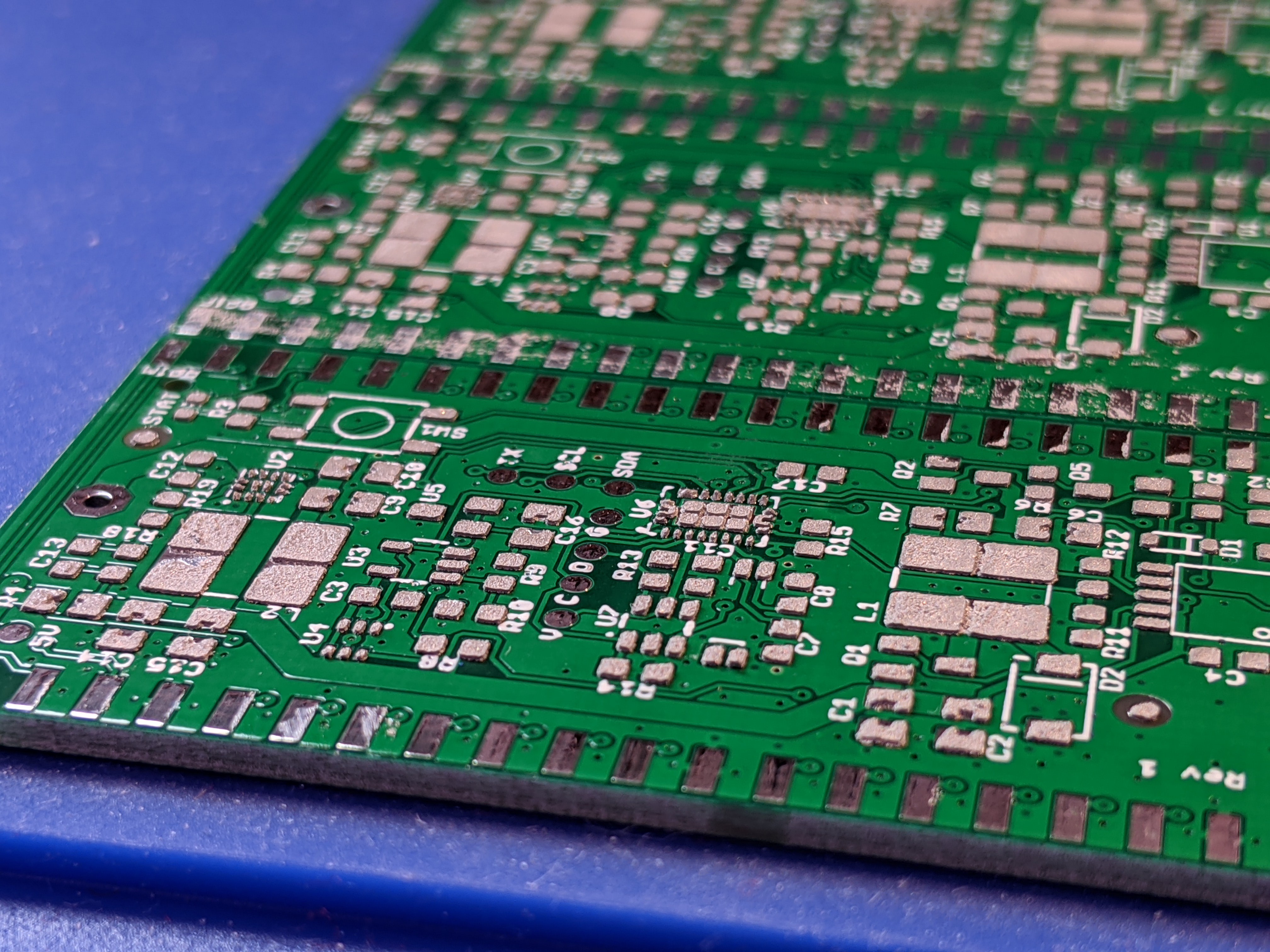
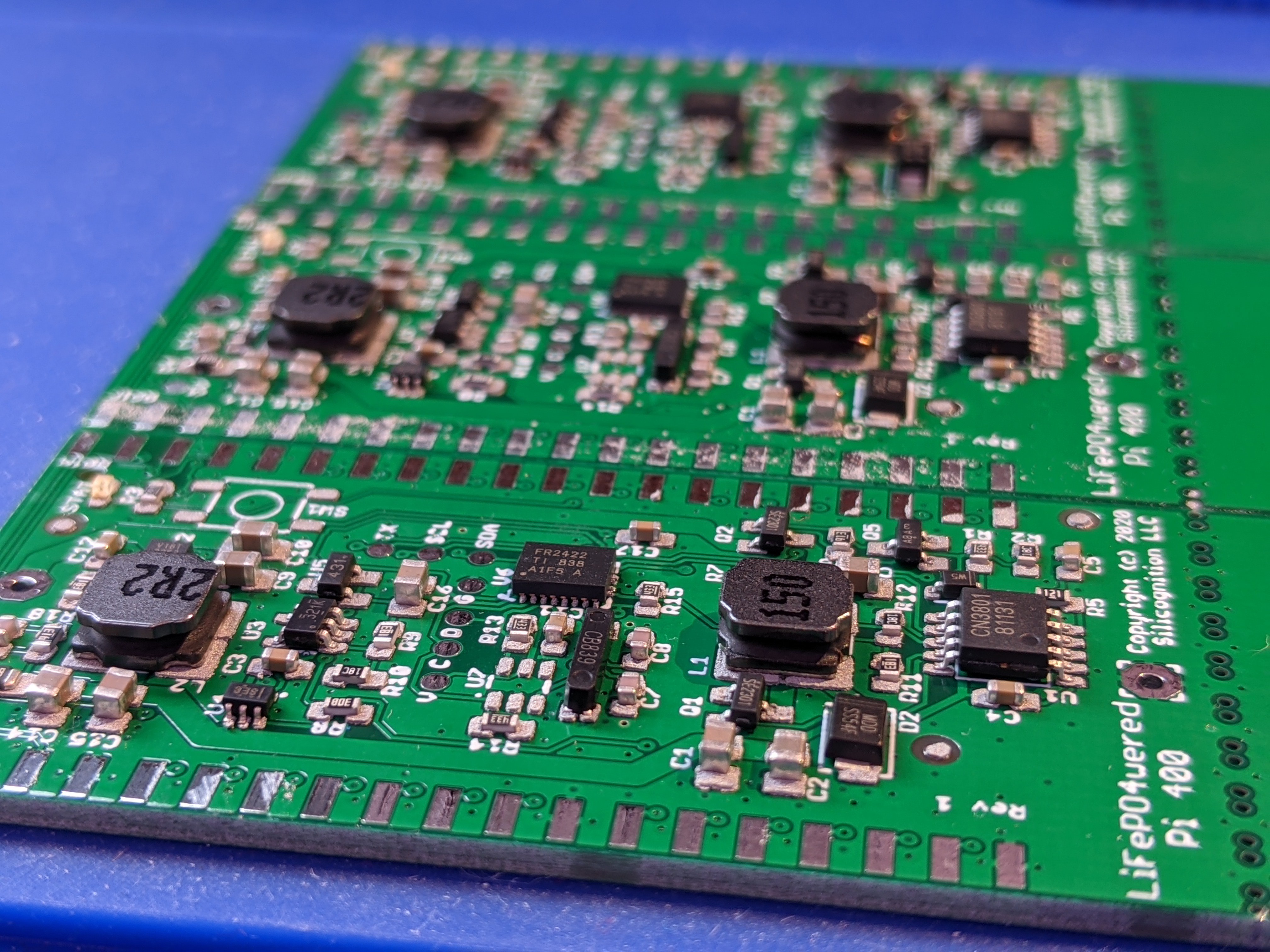
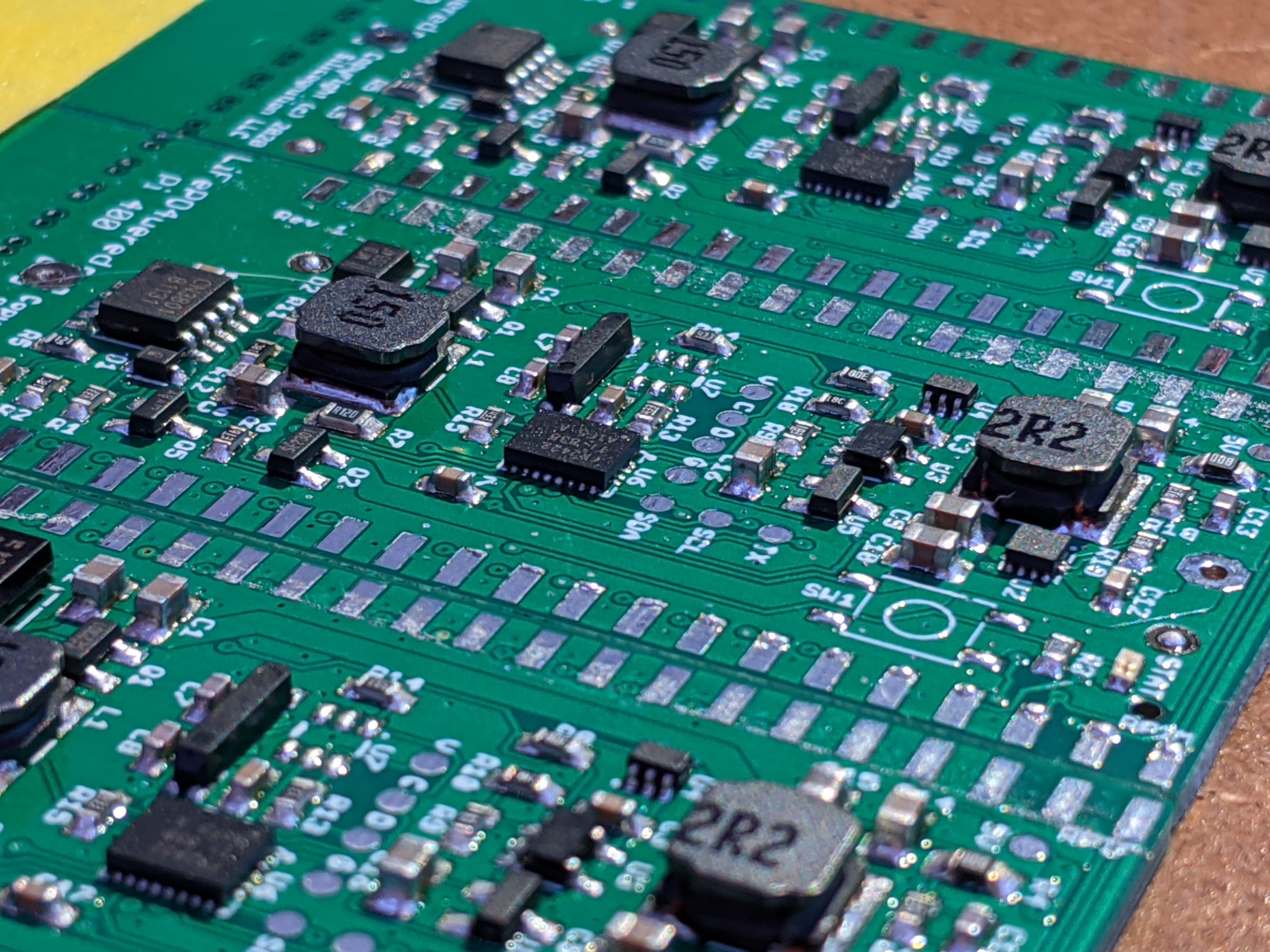
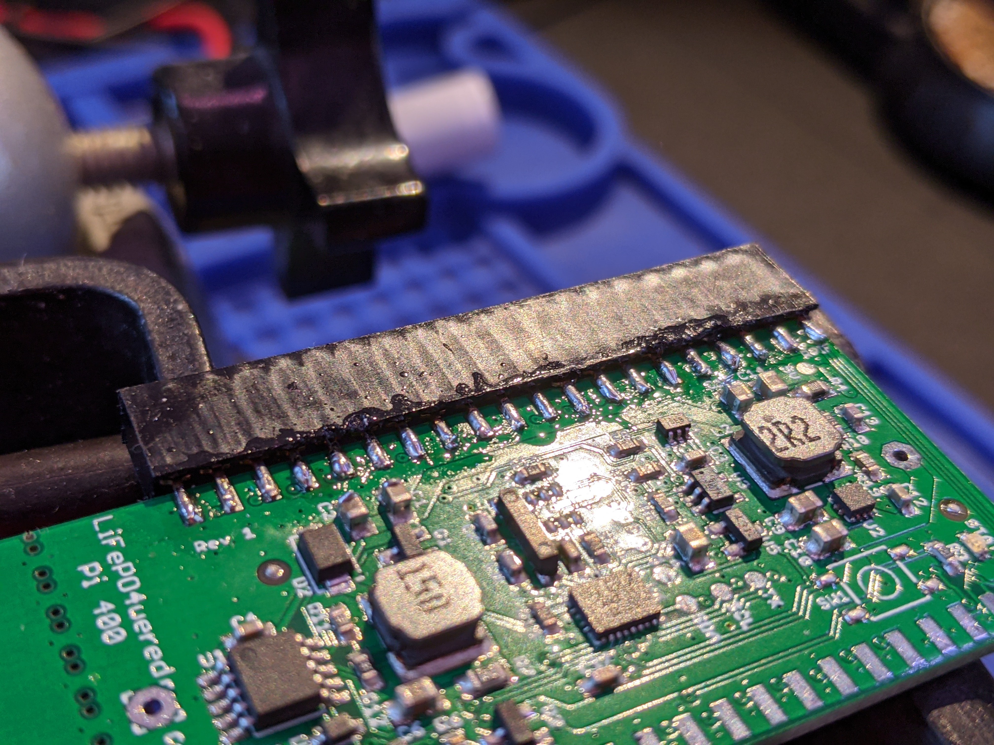
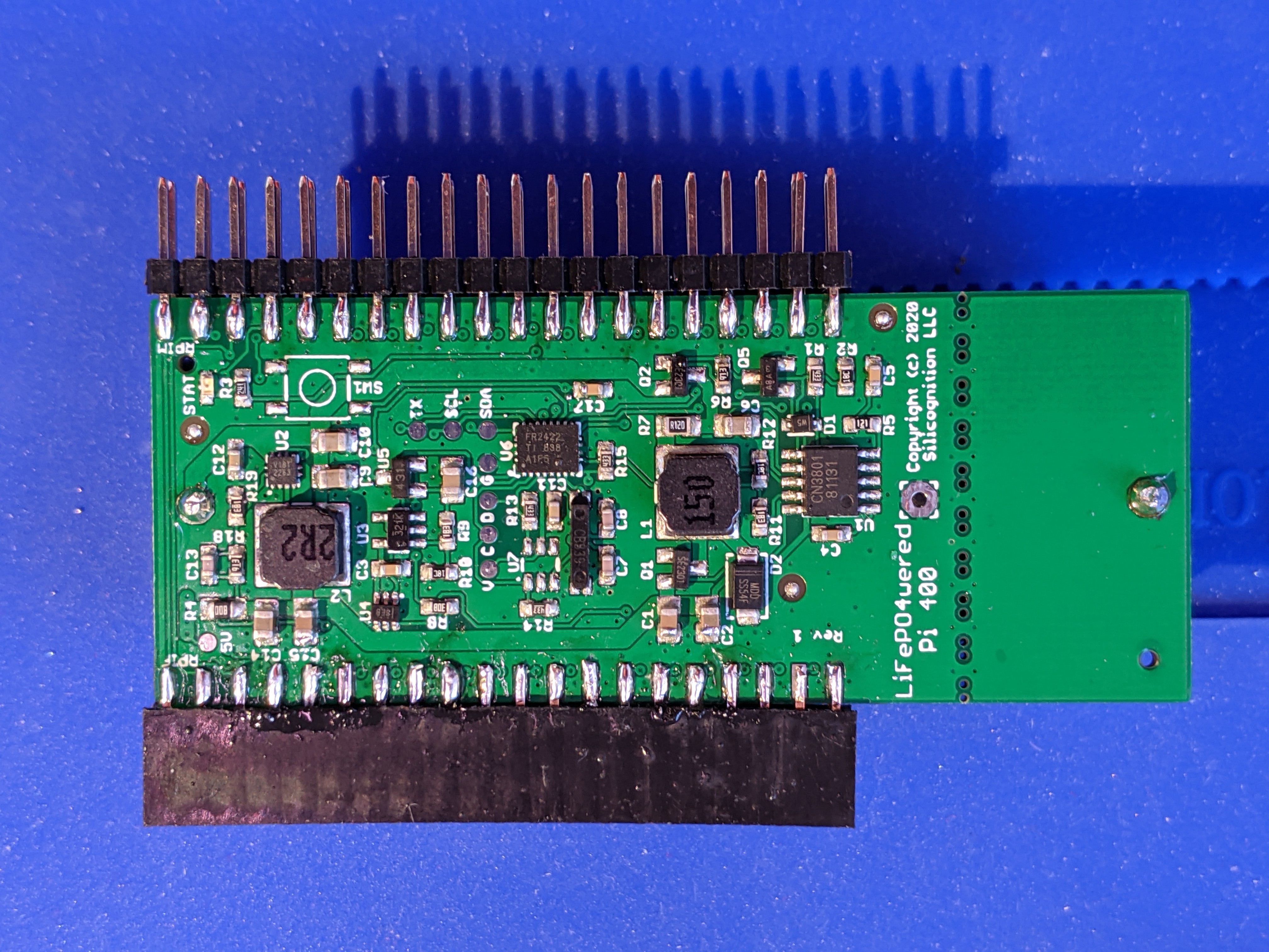
Physically this will be a cartridge that plugs into the GPIO port on the back of the Pi 400, with a duplicate GPIO header coming out the other side so it is still available for other uses.
External power will be connected to the existing power input of the Pi 400, so this will only be dealing with 5V. Not dealing with higher voltage input and things like solar will simplify this a lot. The system will boot when external power is connected to the Pi 400, and if external power is removed, a clean shutdown will be triggered after which power will be removed. Or the user may have the option to keep running from battery power.
There will be a button to turn on the Pi 400 from battery power and to trigger shutdown, but since the system will be powered using the Pi 400's own power input, it's not possible to remove this power when it's plugged in.
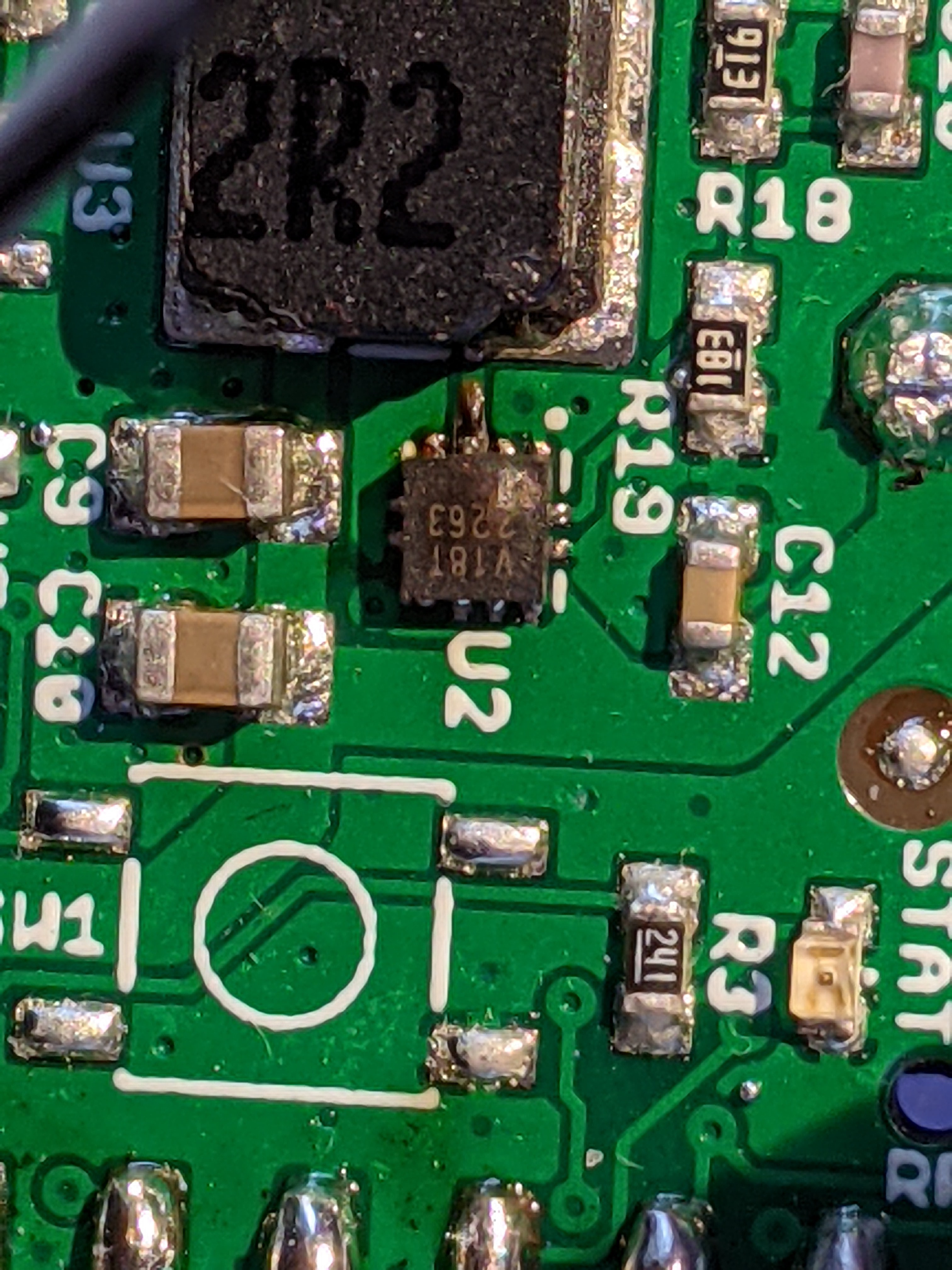
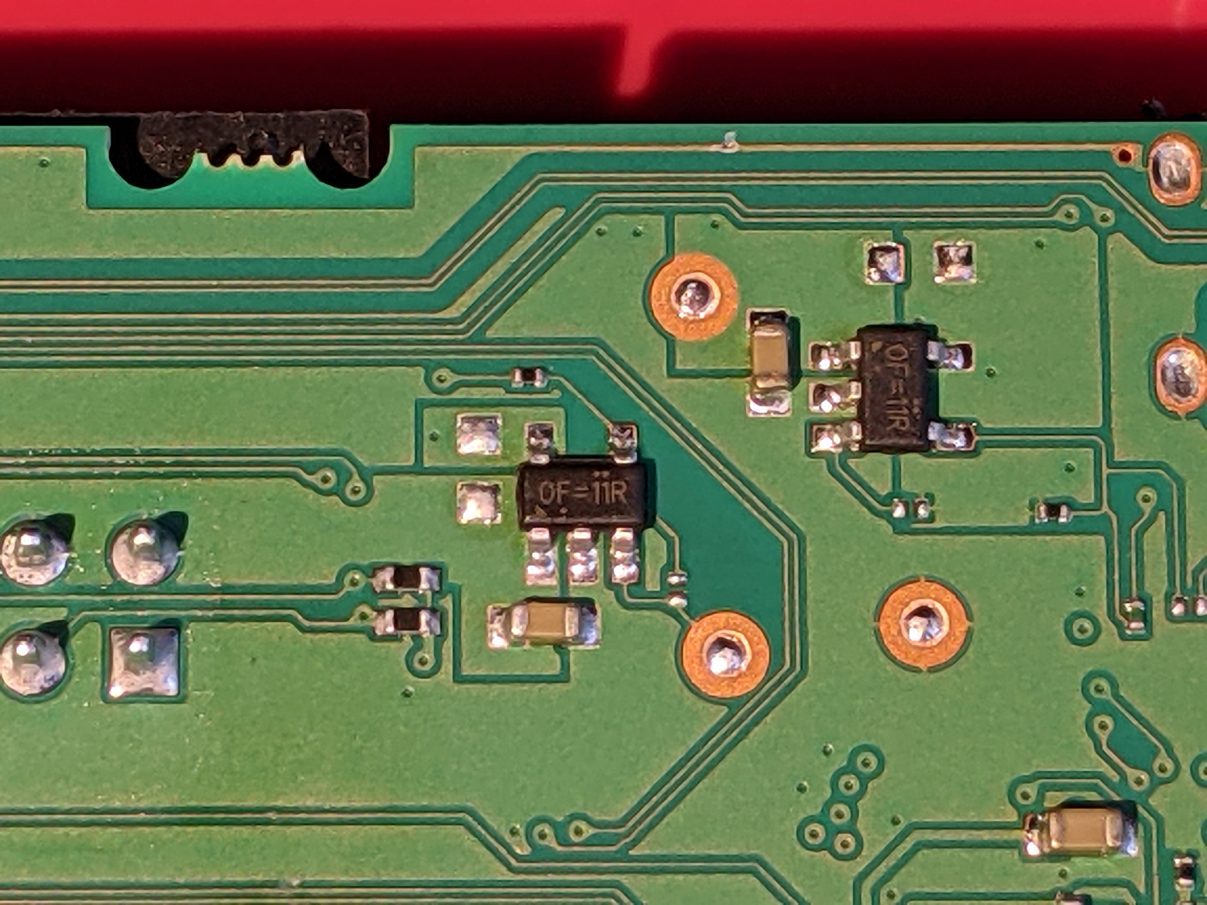
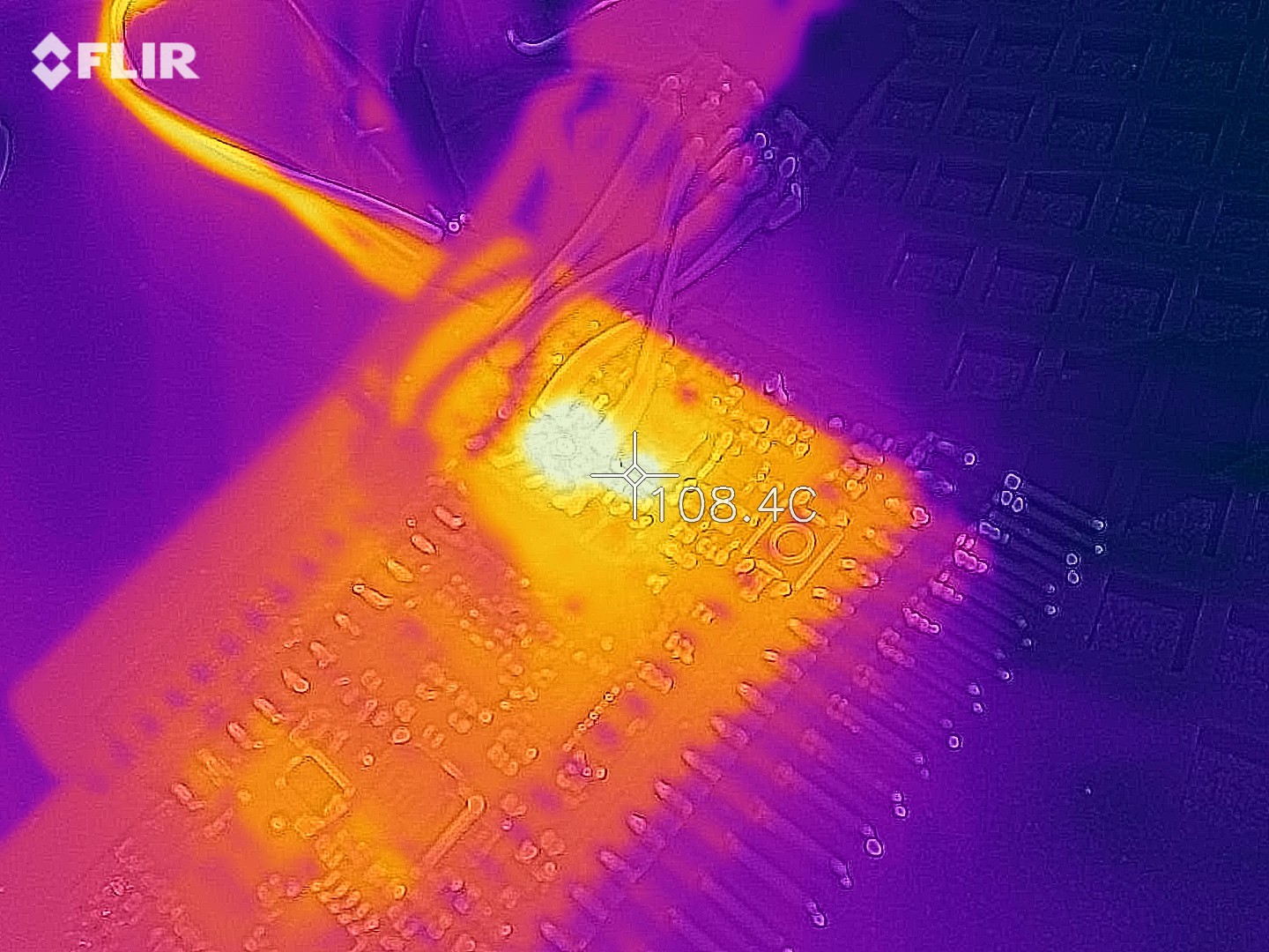
One special feature I'm trying out in this design is to use the Pi's own power input, and use the 5V GPIO pins both to charge the battery when external power is present and supply power when external power is removed. I will be using a boost converter with true output turn-off, and the goal is for it to be enabled while external power is present, primed and ready to take over as it were. Its setpoint will be slightly less than the incoming 5V, I'm starting with 4.85V. Since the 5V rail will be at higher voltage than its setpoint, it should be at 0% PWM, not doing anything. Then when external power is removed, the voltage will start to drop and the boost converter should kick in, ramping up PWM to maintain the voltage at 4.85V.
 Patrick Van Oosterwijck


 Xiaoj329
 Paul Crouch
So I was wondering if you or anyone else would be able to provide any info on that ribbon connector used for the keyboard portion of the Pi-400. I haven't been able to get my hands on a Pi-400 yet, but I've got this idea of putting one inside of a custom mechanical keyboard. I'm curious what the interface between the keyboard and the main board looks like. I'm guessing there's some kind of MCU on the other side of that cable, but it's also possible that it's going straight to a matrix encoder.
This whole thing would be a lot simpler if the Pi foundation would actually update their hardware schematics. It's really annoying that they seem to have gotten so lax about keeping those up to date.