-
Shelved it
12/10/2021 at 20:54 • 3 commentsThis project has been shelved because the Pi400 load switch on the 5V GPIO makes it pretty much impossible to reliably power the thing through the GPIO. Too bad, but not much can be done about it.
-
Some bad and some good
12/02/2020 at 23:26 • 1 commentHaving established that when the Pi 400 is on, the load switch can conduct both ways, it was time to check whether the UPS can keep the Pi running when external power goes away. I connected the prototype to the Pi 400 and the debug probe. I had some init code to set the pins correctly, after which I paused execution and used the IDE to manually enable the boost converter.
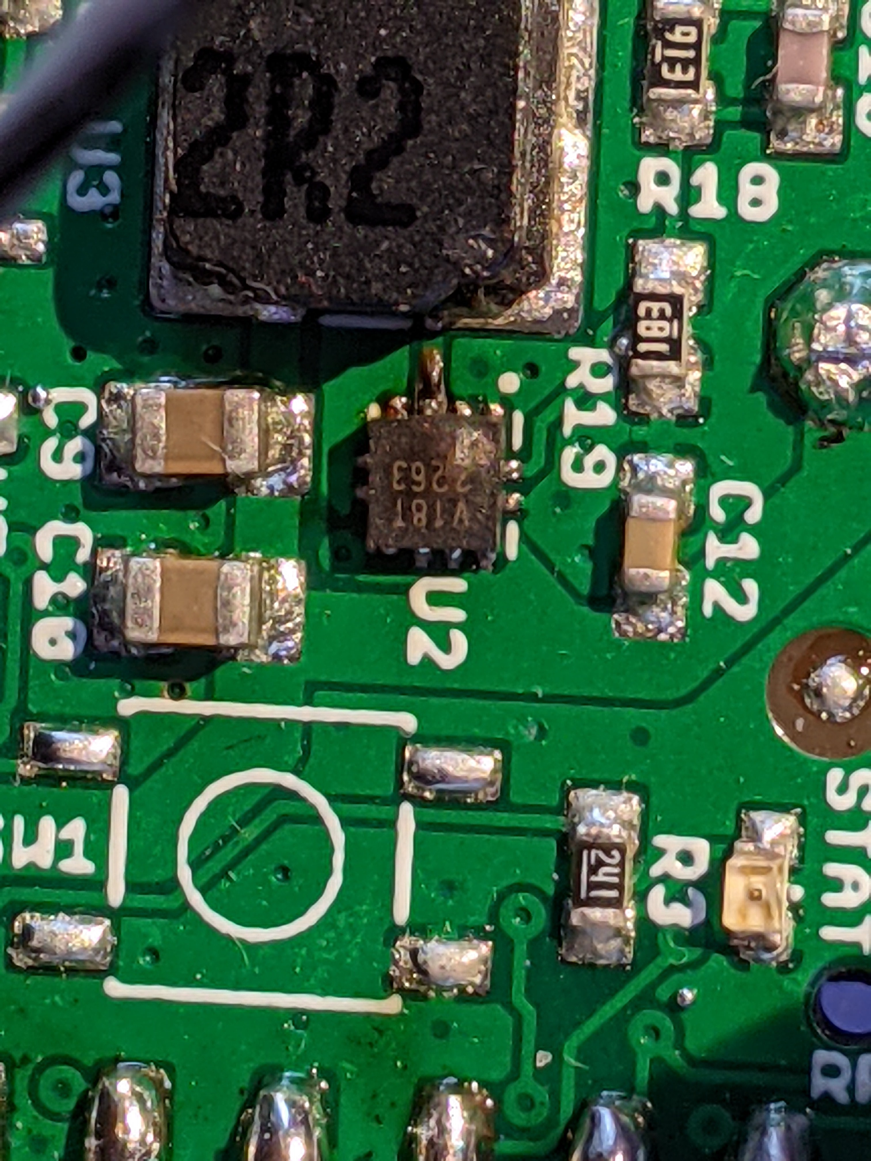
Then the magic smoke came out. :( What the heck?
![]()
Yep, the boost converter burned out.
I am very confused. I had already checked that the boost converter did the right thing when external power was applied in the very first project log I thought? The only difference is that I checked it with a lab supply instead of a Raspberry Pi (and its supply). Could this make a difference? Does anyone have an explanation as to why this would work when the external voltage is applied by a lab supply versus a wall wart?
I guess I'm happy it blew up so early in the project versus much later, after doing a bunch more work. The worst case would have been if it all seemed to work while I was prototyping and developing the whole thing with one particular supply, and then blew up when someone used another supply. My only loss now is the layout work and three prototype PCBs.
So, where to go from here? Well I don't feel like giving up just yet. It's not because a specific part fails that the whole concept is trash. So I decided to test the concept with a really simple setup. I connected a test circuit with two tiny 100 mAh LTO (Lithium Titanate) cells in series to the 5V GPIO. The nominal voltage of LTO cells is 2.4V, so two of them in series is close enough to 5V. LTO cells have low internal resistance, so even small cells have high enough current capability to power a Pi. For a short time at least.
Plugged in, time to pull the power cord:
![]()
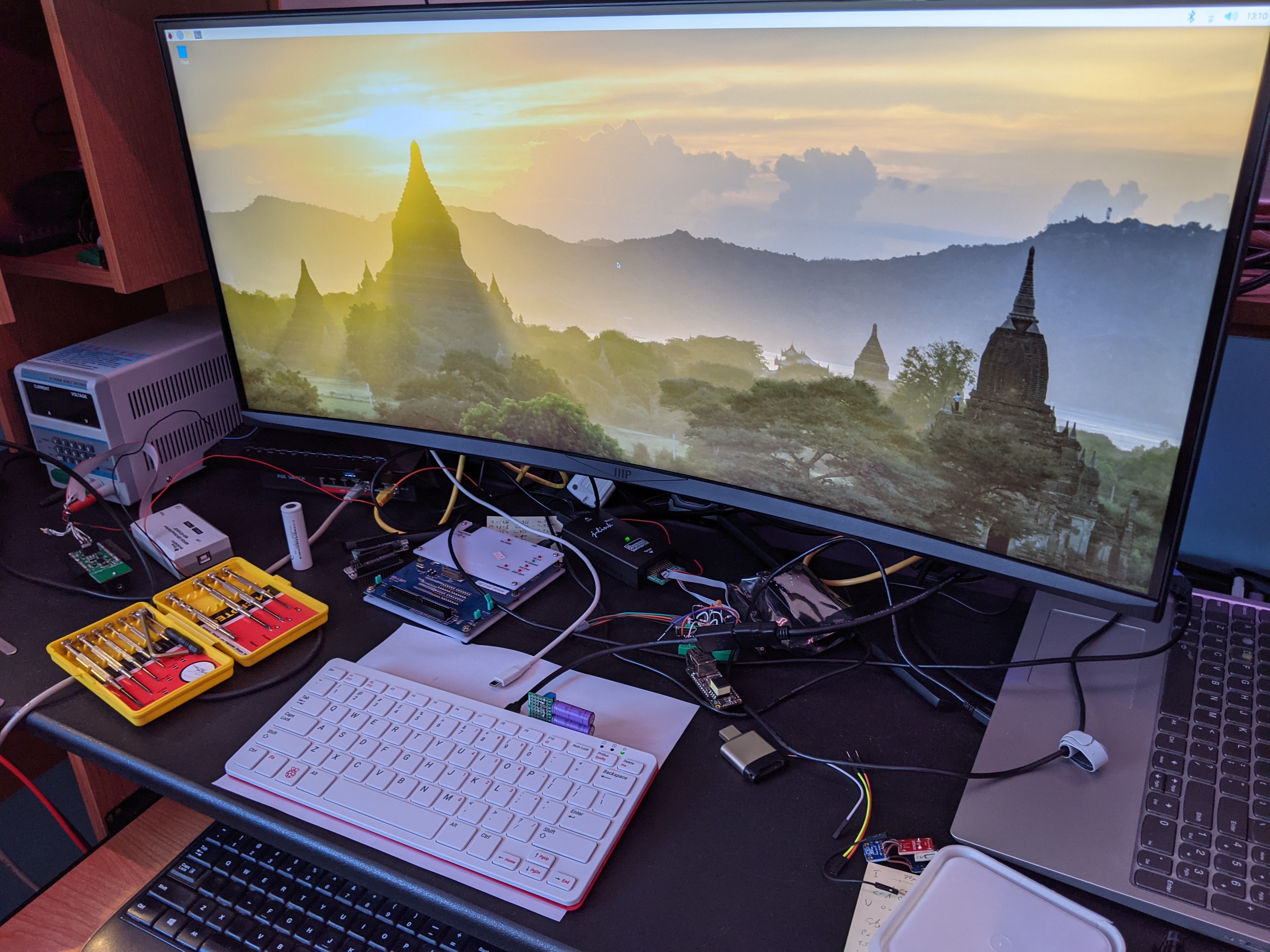
Excuse the mess on my desk, but you can see the Pi 400, with power cord pulled, still running from the two little purple LTO cells!
How long can it run? Well I did some testing with even smaller 60 mAh LTO cells. Running the "stress" test utility, it lasted about 10 seconds. Playing a video in the browser, about 22 seconds. Just idle at the desktop, I stopped the test after a minute but it was still going. I think the limit is not so much the capacity of the cell, but the voltage loss due to the cells' internal resistance and the loss across the Pi 400's GPIO 5V load switch. When the battery voltage gets down to about 4V, the Pi turns off.
So if shutdown is immediately triggered when loss of power is detected (terminating high load processes with it), this may be a workable design! I may not even need to add a power switch on the UPS, I could actually take advantage of the load switch in the Pi 400 which drops leakage current into the 5V pin to less than 1μA! But I probably will, because of the 40-pin header pass-through design I'm going for. The key to making it work will be to accurately detect whether current is flowing into the battery or out of the battery to the system, and immediately signal a shutdown to the Pi when power is provided by the battery. I may be able to salvage the current sense amplifier circuit from the failed design for this purpose.
-
Raspberry Pi 400 analysis
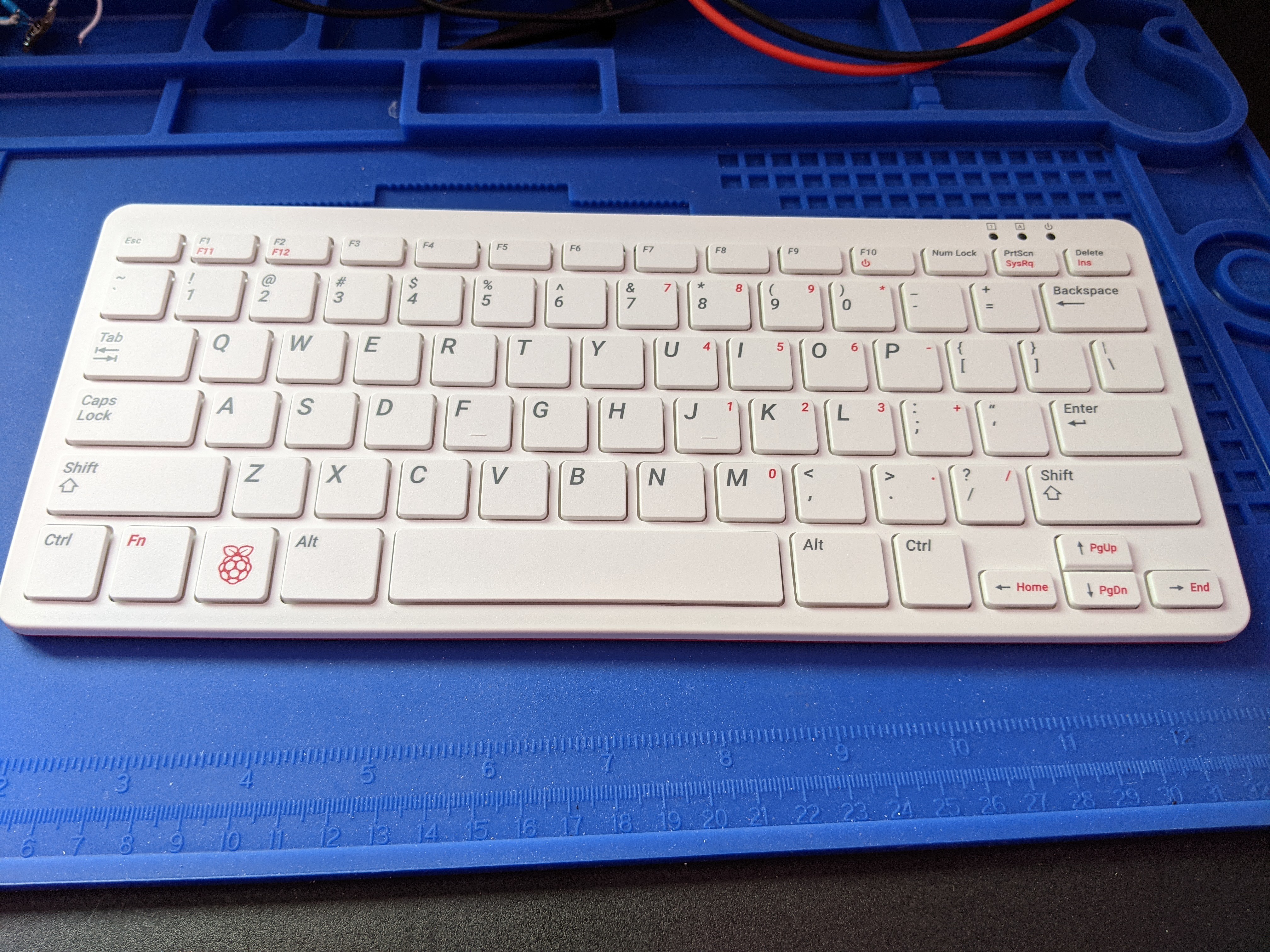
12/02/2020 at 17:08 • 2 commentsI finally received a Raspberry Pi 400:
![]()
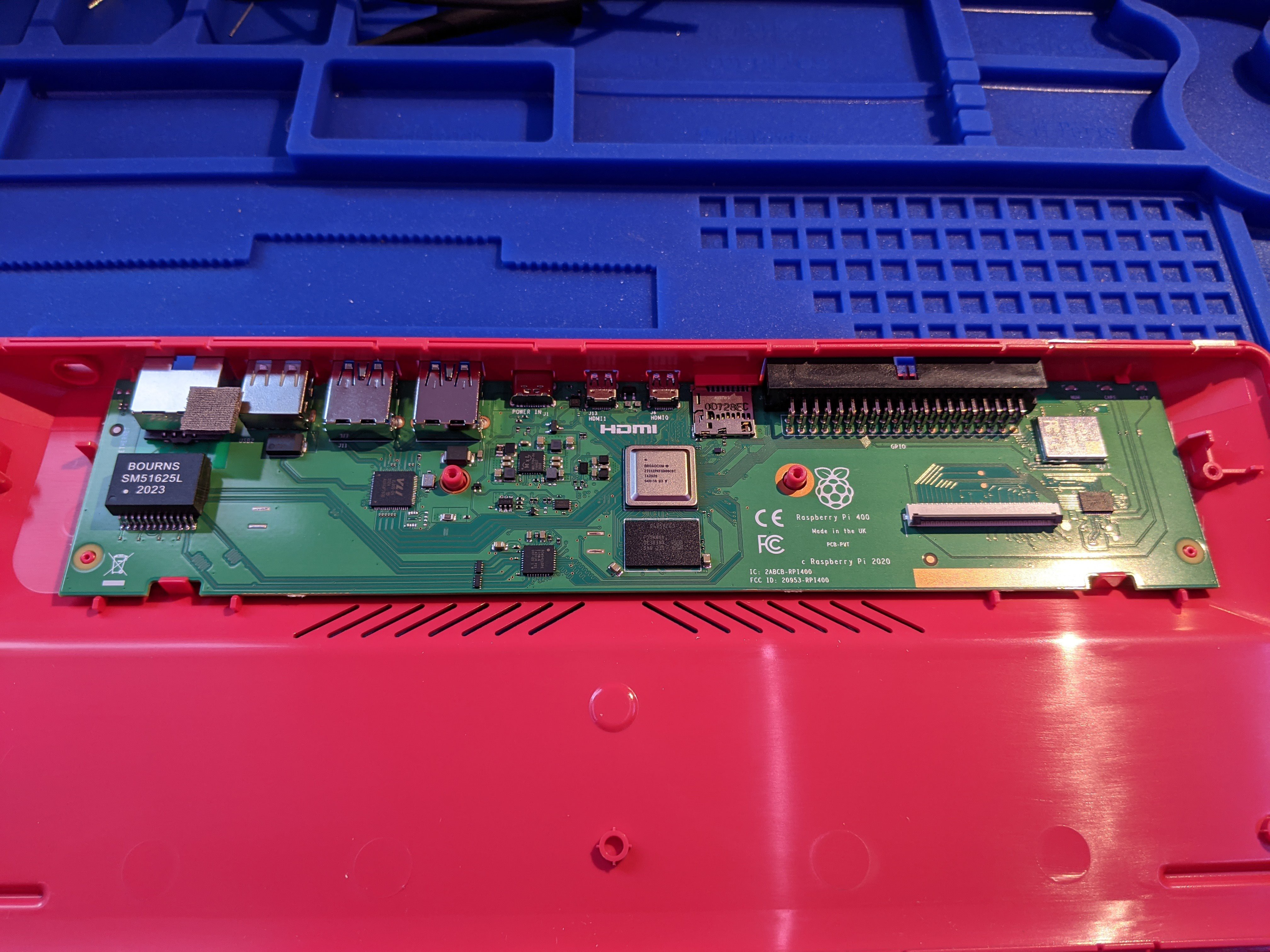
Time to take it apart and see what's going on with the GPIO 5V!
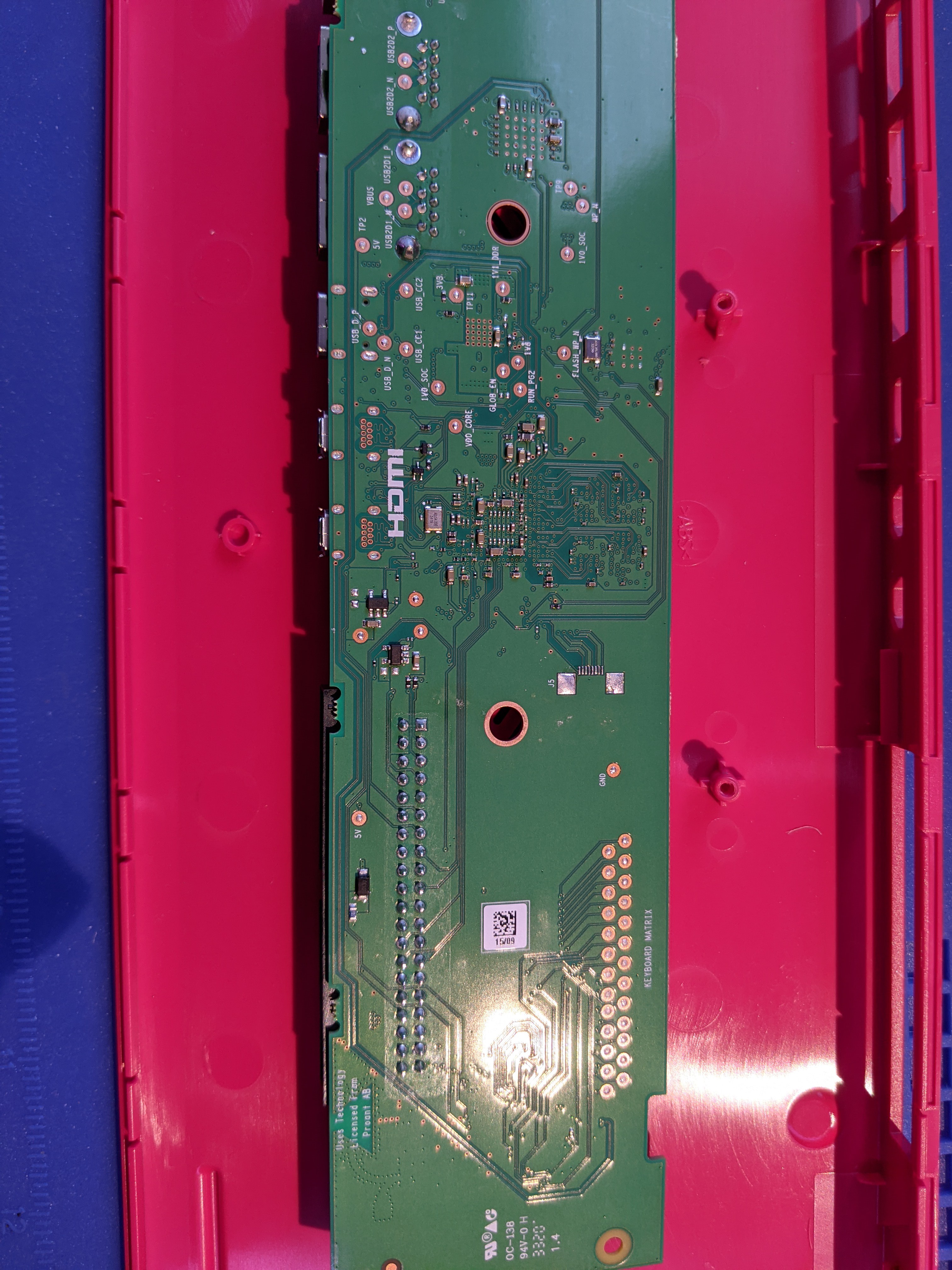
![]()
![]()
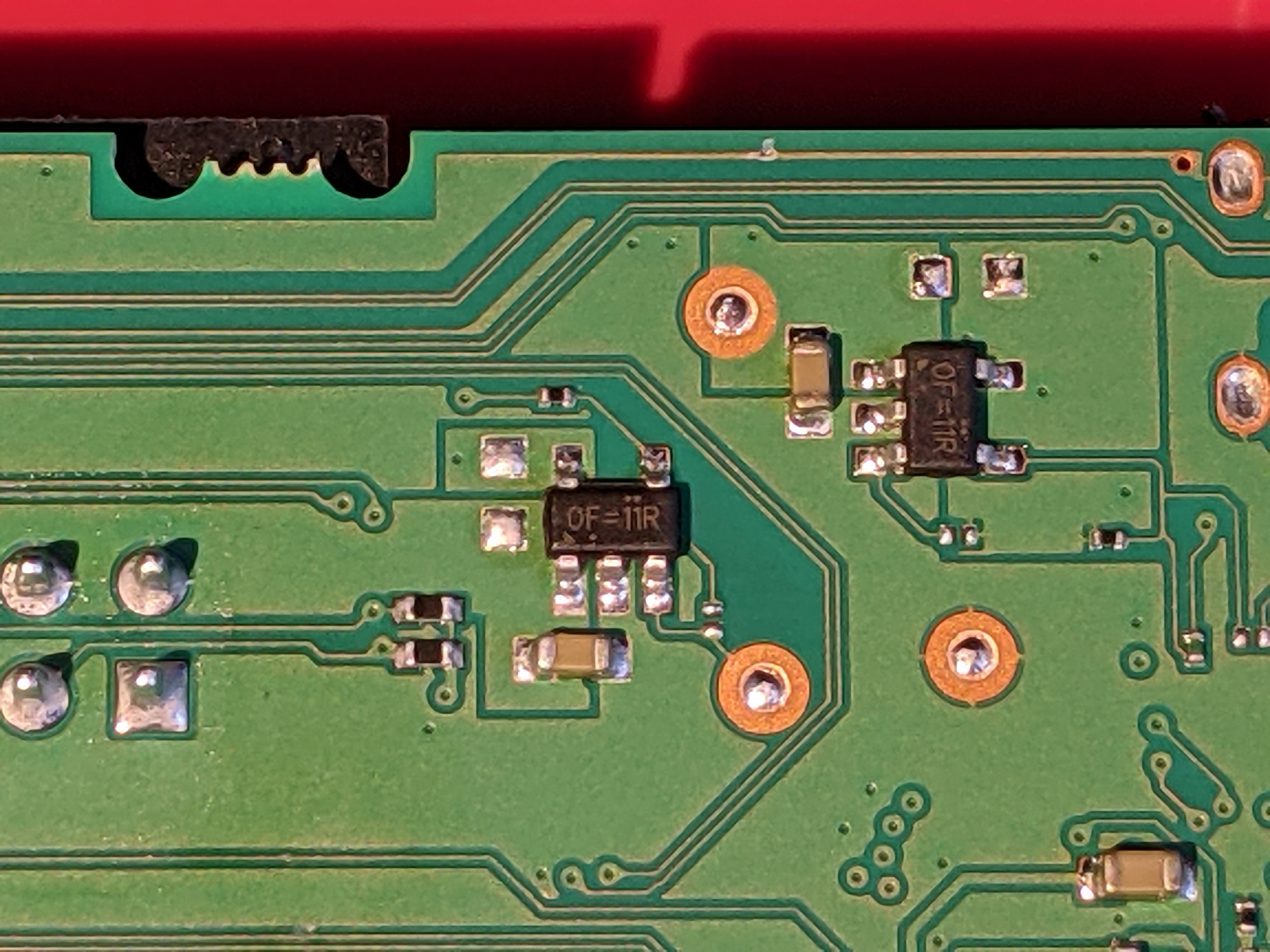
Most reviewers talked about the top size of the PCB and pretty much ignored the bottom. Contrary as I am, of course my main interest of course is on the bottom, specifically with these two parts:
![]()
These are identical parts, presumably the load switch talked about. Two of them: one to switch 5V and the other to switch 3.3V. The one in the center definitely drives the GPIO 5V pins, the other one switches 3.3V but oddly is not connected to the GPIO 3.3V! I think it switches the SD card slot power. Protect the one GPIO power rail but not the other? I don't get it.
They are marked "0F=11R". It took some digging to find what exactly they are, but eventually I figured out that they are almost certainly Richtek RT9742 load switches. The connections match the datasheet, as does the "0F=" marking. Oddly, two variants are both marked "0F=": the 3A RT9742ANGJ5F and the 1A RT9742GGJ5. The only difference to tell them apart is that one of them is in the "TSOT-23-5" package and the other in the "TSOT-23-5 (FC)" package. But if you check the mechanical outline specification for these packages, they seem to be identical according to the spec. I don't know what the supposed difference is then.
So I decided to just test which one it is. I hooked up my electronic load, and increased load from 1A up in 0.1A steps. It tripped at 1.4A, so it's the RT9742GGJ5 1A version.
The datasheet has this info about the pass transistor: "Unlike a normal MOSFET, there is no parasitic body diode between drain and source of the MOSFET, the RT9742 prevents reverse current flow if VOUT is externally forced to a higher voltage than VIN when the chip is disabled." So indeed no hope of turning the Pi 400 on from GPIO power.
Once the Pi is on, it may be possible to preserve power long enough for shutdown though. The datasheet says: "If VOUT is greater than VIN, current will flow from VOUT to VIN since the MOSFET is bidirectional when on." So UPS functionality is still possible.
-
Problems
11/23/2020 at 22:51 • 1 commentI guess that one update was where the good news ended. *lol*
I found out today that the Pi 400 seems to have a 1A load switch on the 5V pins going to the GPIOs. Not that there's any good way to find out since I can't get hardware here and the Foundation still hasn't bothered to release schematics! Lately it's like they are actively working to try and make the life of third party developers such as myself difficult. They've never been the poster child of openness, but it's getting worse all the time. It's like they're trying to become Apple, making shiny consumer gadgets and have forgotten their original mission of providing a hackable product.
Anyway, if this is the case, the approach I'm taking here likely won't work. Not sure if anything would work really. It is possible that once the load switch is turned on, I can send power back to the Pi. But I don't know by what mechanism the load switch is turned on. Also, it's a 1A load switch so depending on how much other stuff is connected to the USBs etc, there may be more than 1A flowing through it once I'd start to power the Pi.
It pretty much means that "running the Pi 400 from a battery" is pretty much out. Working as a UPS may still be salvageable. Only testing will tell. This topology may need to morph back into the original "simple UPS for a normal RPi" if it doesn't work for the Pi 400. The Pi 400 may need a different approach, involving only the USB Type-C power input.
I also did some load testing on the G2263 boost converter. This is supposed to be a 9A switch current part, a "compact solution for a 5V output, 4A load requirement" according to the datasheet.
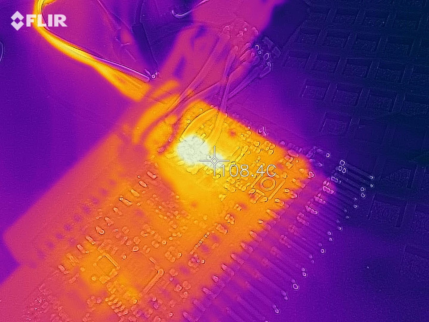
Well, in my testing it seems to be a whole lot less than that. I don't know what the limit is, but when I tested at 2A, the part got very hot (>150 °C, the maximum my FLIR can measure) and went into a hiccup mode (probably thermal protection kicked in to try to save the part from burning up). I tested it at 1.5A load and this is the thermal image for that:
![]()
Still very hot but at least it seemed stable. This heat production is another indication that UPS duty may be a doable goal while running for long periods from the battery isn't really. The part can provide 1.5-2A for a short period of time, long enough for shutdown to complete.
I have also confirmed that the current sense amplifier seems to do its job (although the reading seemed a bit high, but that might just be due to trace resistance that isn't yet taken into account). It outputs a positive voltage versus a reference when power is produced from the battery and a negative voltage when the battery is charging. That should do the job for being able to detect whether external power is provided to the Pi or we are providing the power from the battery.
-
Prototype build
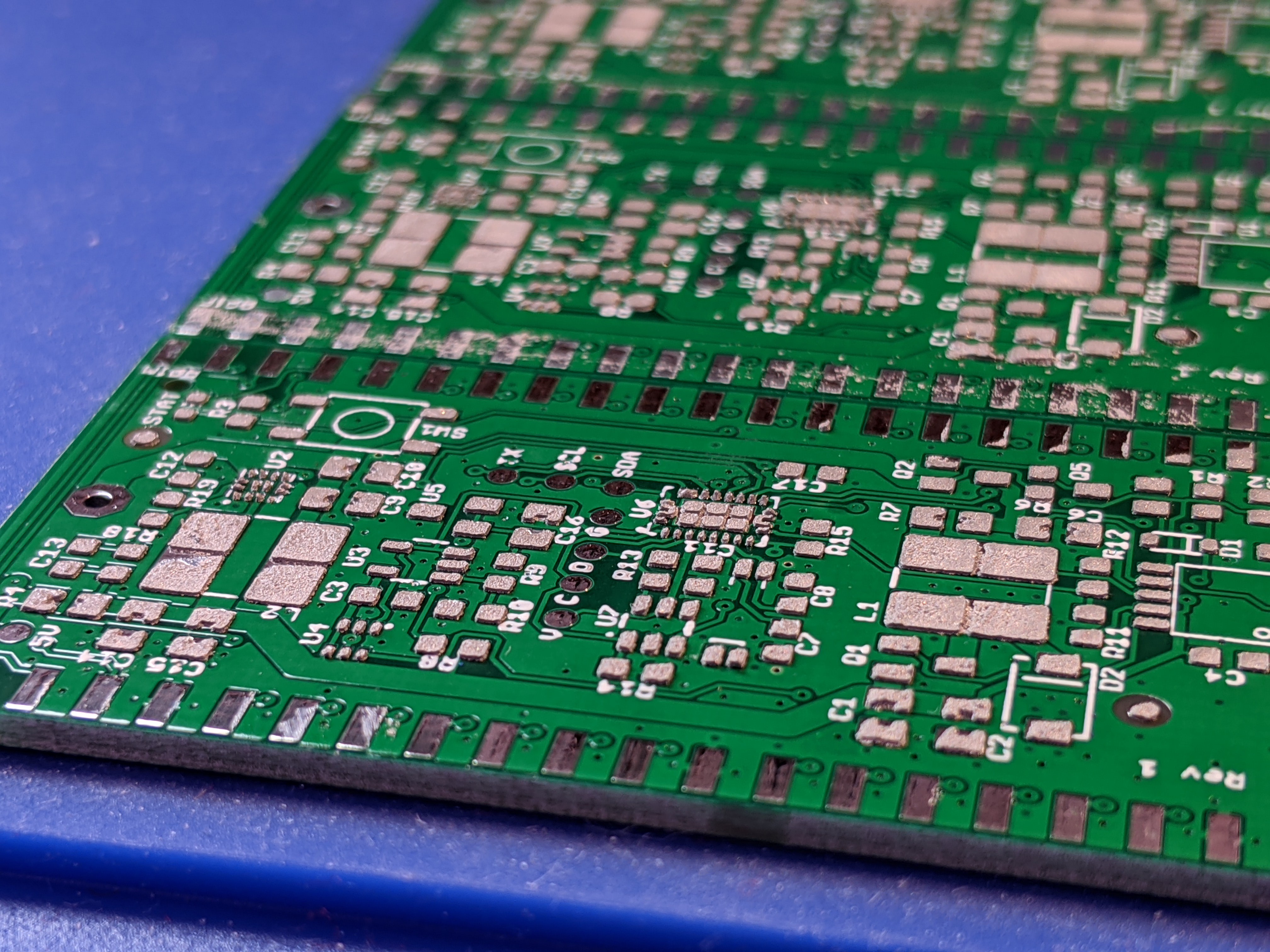
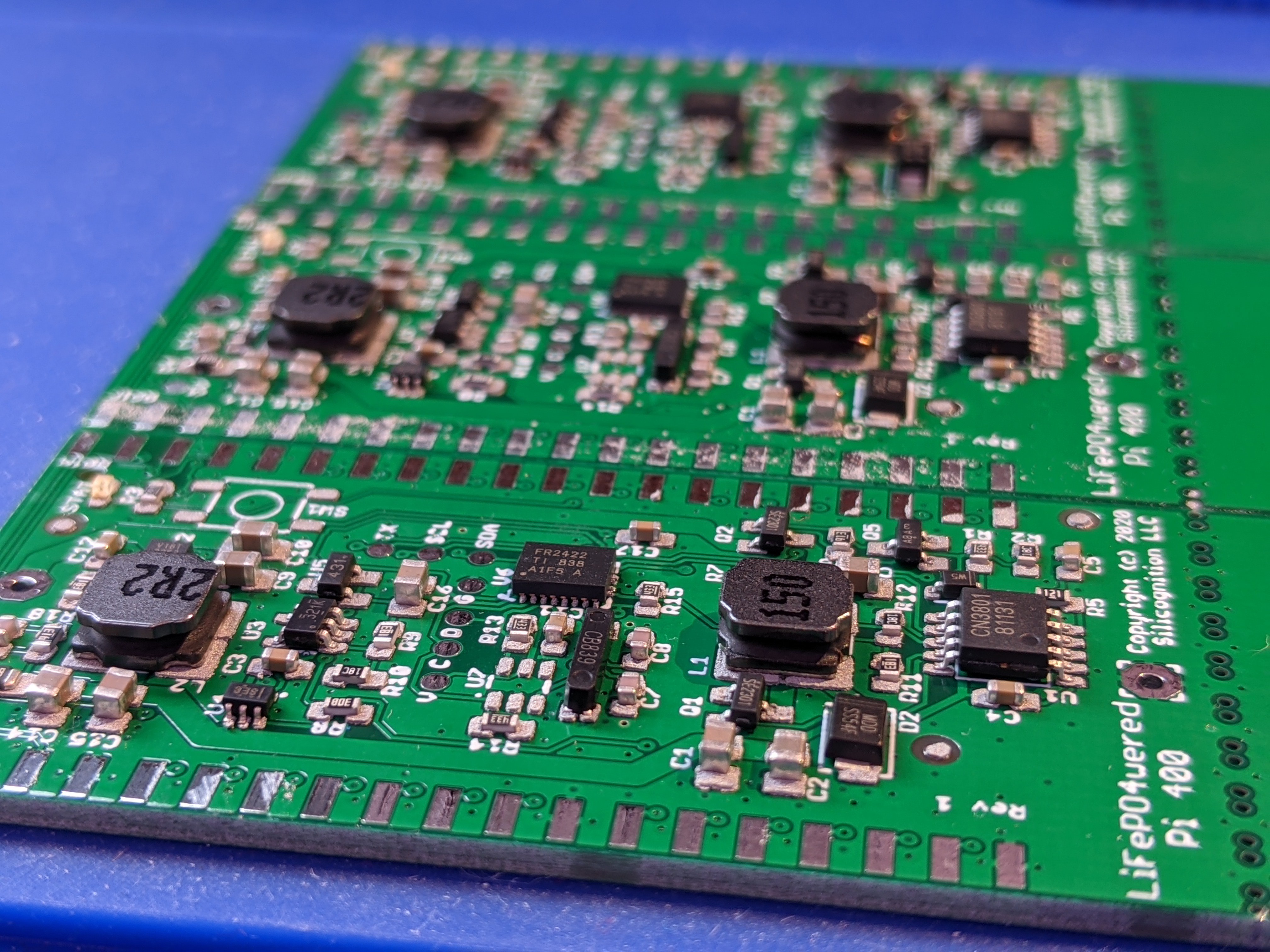
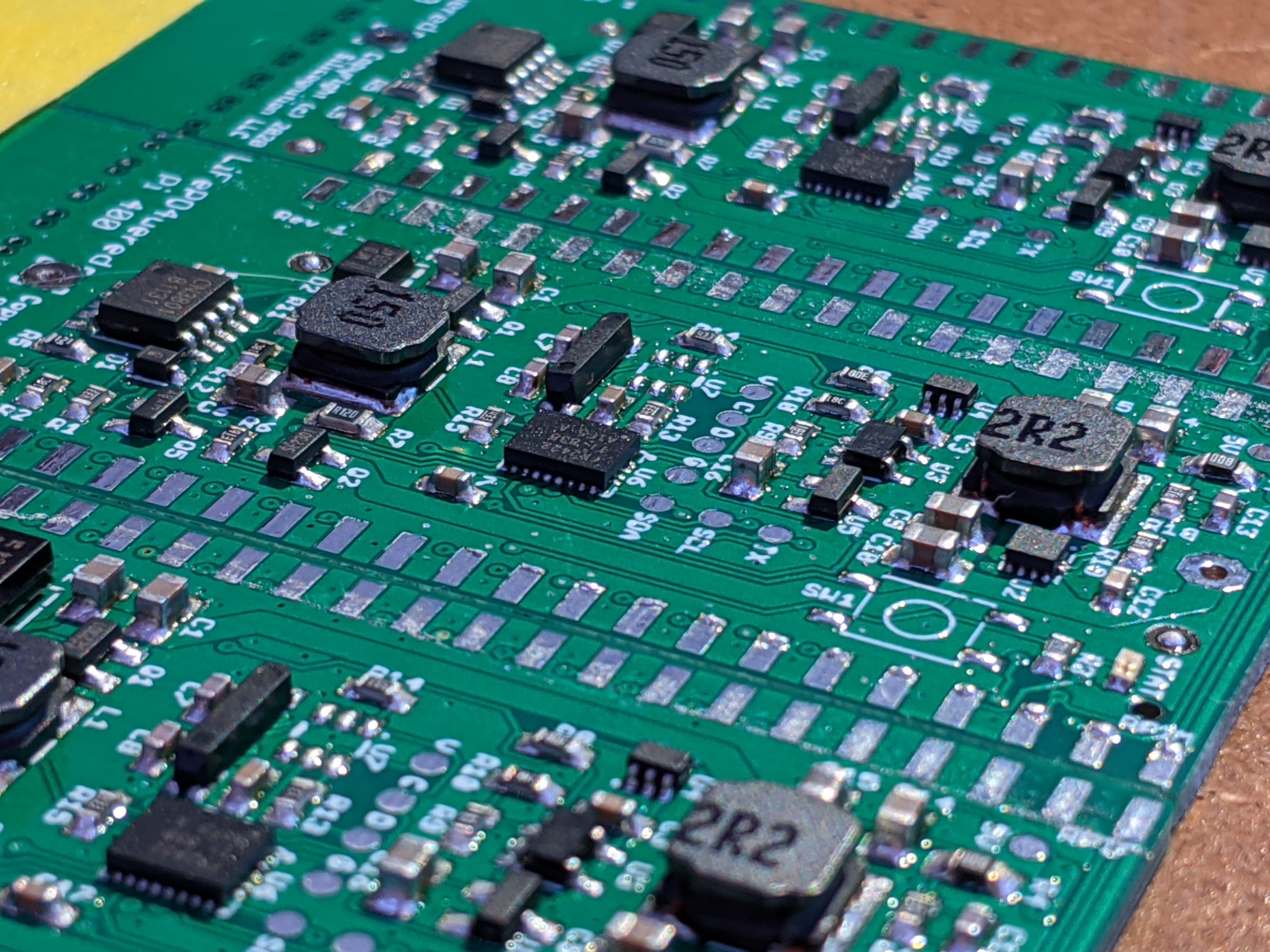
11/23/2020 at 05:37 • 0 commentsAfter creating the design, I ordered prototype PCBs and stencil from JLCPCB. This log documents the build of three prototypes.
![]()
![]()
![]()
The SMT part of the build went very smoothly. No obvious shorts I needed to deal with. Two parts are still missing: the button (SW1 which didn't arrive yet and I'll add later) and there's a footprint for a low cost 6-pin Padauk micro (U7) which will be used to enable firmware update of the MSP430 over I2C BSL. No point in mounting an OTP micro until I've figured out its programming. :)
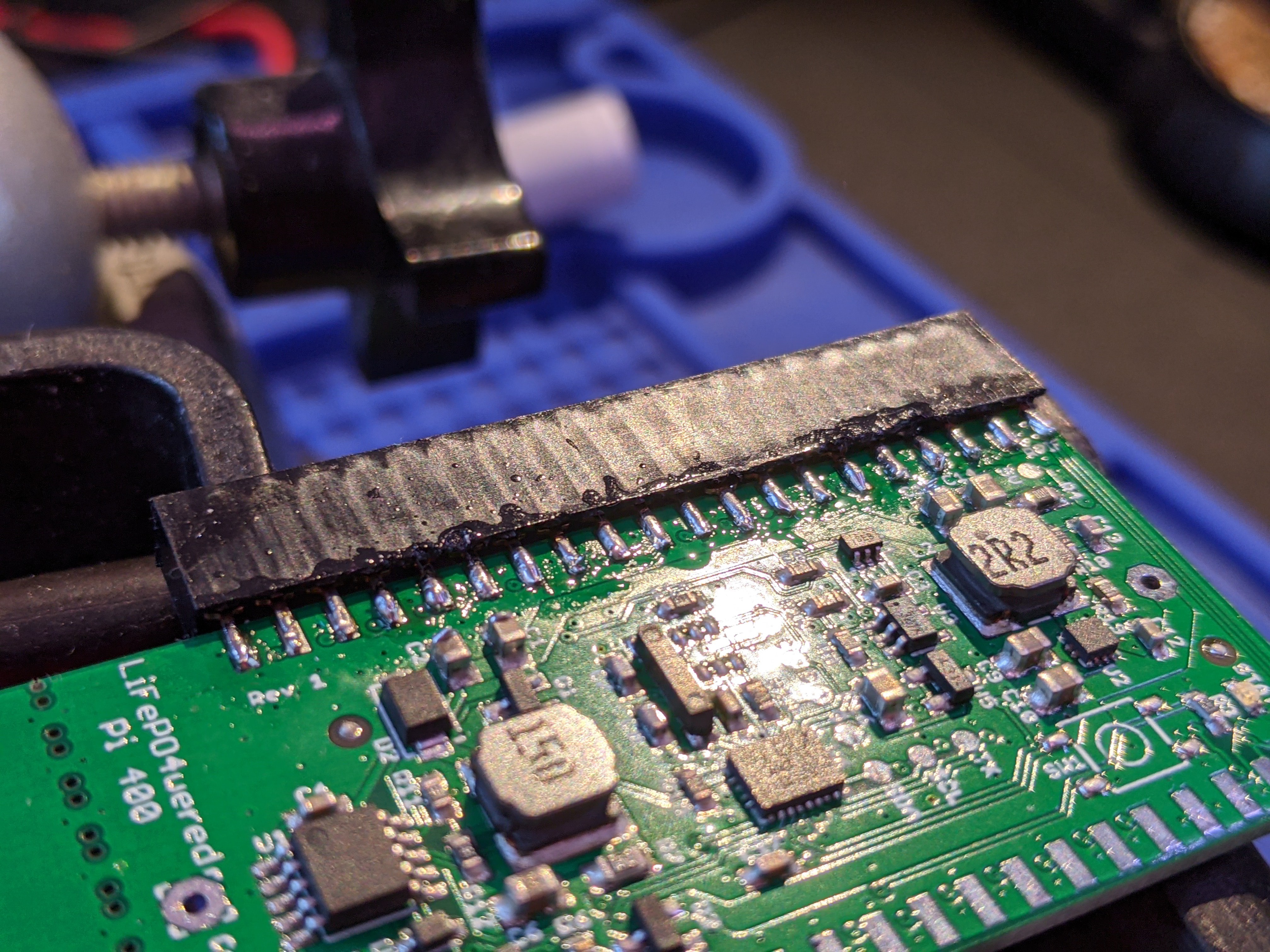
After such a smooth SMT build, connecting the headers unexpectedly was a whole lot more troublesome:
![]()
Ugly, I know. I had a lot of trouble getting both the pads and pins to wet and connect. In hindsight, the pads are too small as they are completely under the pin so they're hard to heat together with the pin. Also, the board is thinner than the spacing between the two rows of pins, so there's a gap that needs to be bridged. I'll have to investigate thicker PCB options for a better fit.
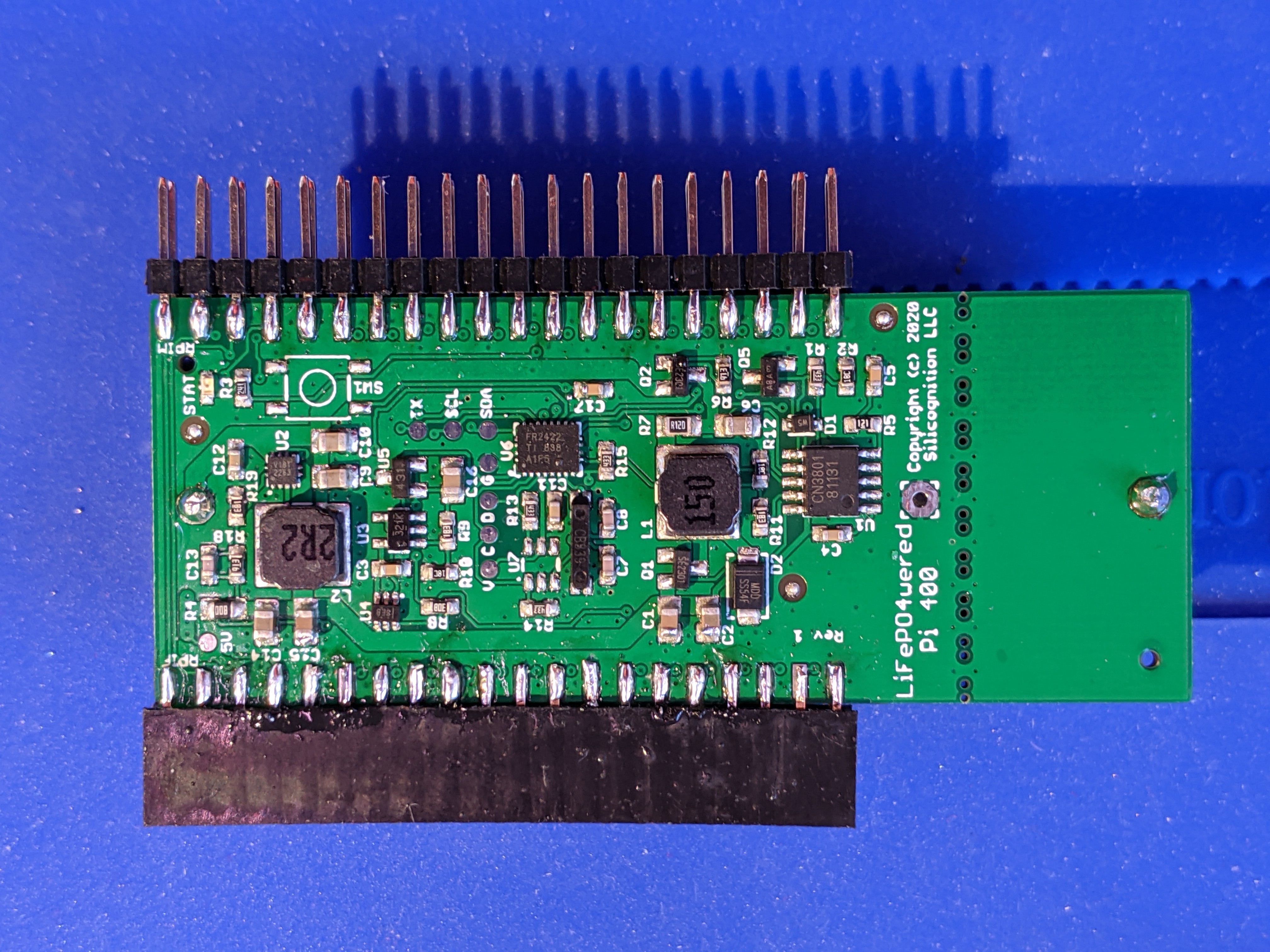
I got a prototype together in the end:
![]()
The battery holder for an 18650 LiFePO4 is on the bottom of the board. I was able to confirm some basic functionality:
- I could connect to the MSP430 microcontroller using the MSP430-FET.
- I could enable the 32 kHz crystal oscillator for system clock generation and RTC timekeeping.
- The battery would charge when external power was connected and charging enabled.
- The boost converter would generate ~4.85V when enabled (I did not test current capability yet).
- The boost converter could be enabled while external power was applied and nothing would blow up! The boost converter would simply stop switching with the voltage above its setpoint, and start up as the voltage would start to drop when external power was removed.
This last test was really important, the whole concept of this UPS would stand or fall with the result of this test. And as far as I could tell, it passed with flying colors! I could have the boost converter enabled and apply and remove external power at will, the boost converter would just take over when external power went away and stop providing power when external power came back. You could see the voltage on the scope go from 5V to 4.85V and back to 5V and the whole thing would be completely glitch-free!
Next things to test:
- Output current capability.
- ADC measurements of system and battery voltage.
- ADC measurement of input/output current, and the accompanying detection of whether we're supplying power or external power is present.
Once these are confirmed, I can start writing the firmware for this new micro. It's still an MSP430 like in the #LiFePO4wered/Pi+, but this is a newer generation device with FRAM and enhanced peripherals compared to the part I used in previous designs, so some porting will be necessary.
LiFePO4wered/Pi400
Simplified low cost UPS and battery power for the Raspberry Pi 400
 Patrick Van Oosterwijck