Communications
Maxim's MAX7221 LED Driver chips communicate with the host computer via the SPI (Synchronous Peripheral Interface) bus. SPI based systems normally have a single bus controller (in this case a Raspberry Pi) and one or more target devices (in this case, LED Driver chips). It is normally a short distance bus and transfer rates range from a few hundred Kbits/second up to 25Mbits/second. Most uses of it are at the lower range of speeds. A SPI bus has 4 primary signals and a ground. These signals are:
CS Chip Select or Chip Enable, a usually active low signal that indicates the beginning and end of a SPI transaction. This signal comes from the bus controller.
SCLK Serial Clock, this signal synchronizes the data transfer within the transaction. This signal comes from the bus controller.
MOSI Master Out Slave In, this is the data out of the bus controller, destined to the target device(s). On target devices, this may be labelled Data In. This signal comes from the bus controller.
MISO Master In Slave Out, this is the data from the target devices to the bus controller. On target devices, this may be labelled Data Out. This signal comes from the target device.
One method of creating a bus with SPI communications is via "daisy chaining". Daisy chaining allows connecting multiple target devices in a sequence. Not all SPI devices support the daisy chain method of interconnecting targets, but the MAX7221 devices do. In a daisy chained system, the CS and SCLK signals are common to all devices on the bus. The MOSI signal from the controller is connected to the DataIn signal of the first target device in the chain. The DataOut signal of the first device becomes the InterDigit_Data_1 signal and is connected to the Data In signal of the second target device in the chain. This connection of target DataOut to the next target DataIn signals is repeated for the rest of the devices in the chain as InterDigit_Data_N. In some systems, the last MISO/DataOut signal may be connected back to the bus controller, but in this system, it must not be. The Raspberry Pi runs on 3.3V and the MAX7221 chips run on 5.0V. The last target devices MISO/DataOut pin will be a 5.0V signal that would damage the 3.3V MISO/DataIn pin on the Raspberry Pi. There is nothing useful to read back in any event.
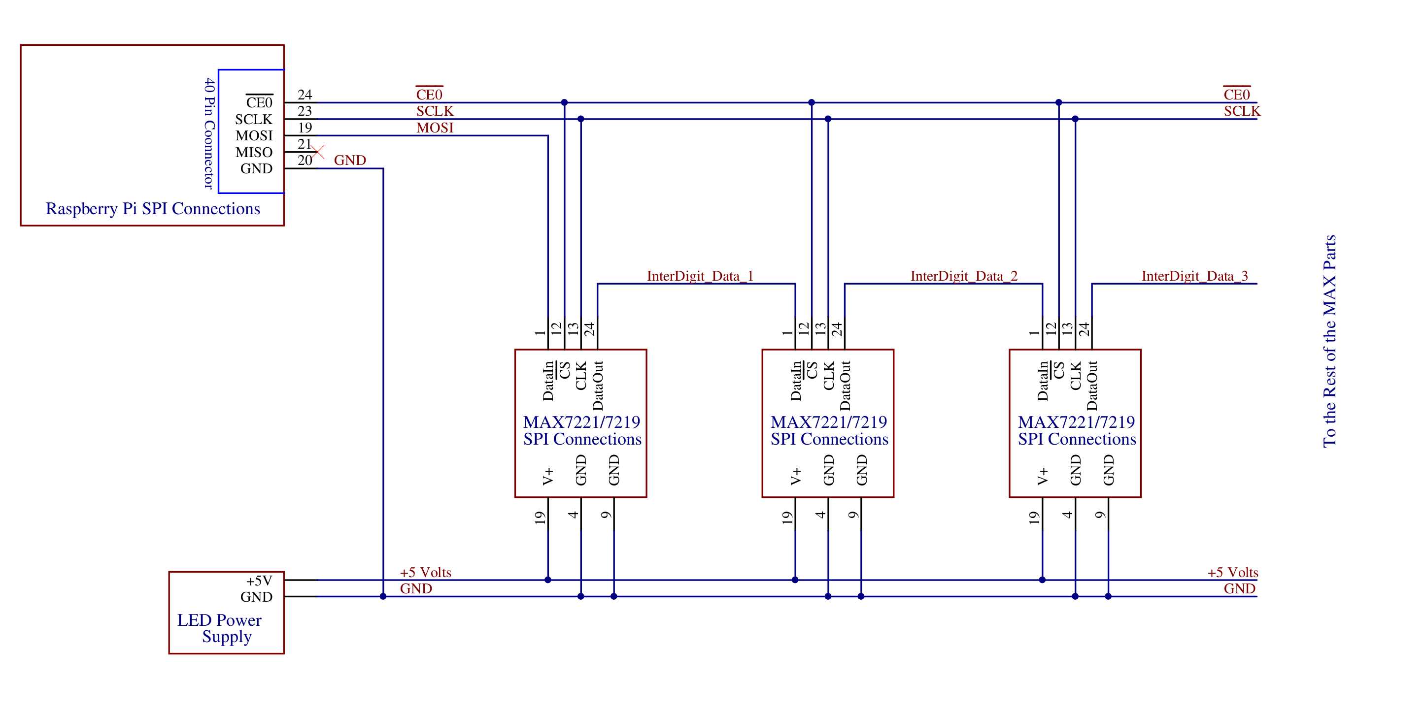
Pin numbers on the Raspberry Pi 40 Pin Connector are shown. Pin numbers on the MAX7221/7219 chips are shown for reference. In practice, there will be connectors on the edge of the board for each display module, but the layout and pin numbering of the display modules are specific to the design of the modules and will vary depending on the module source.
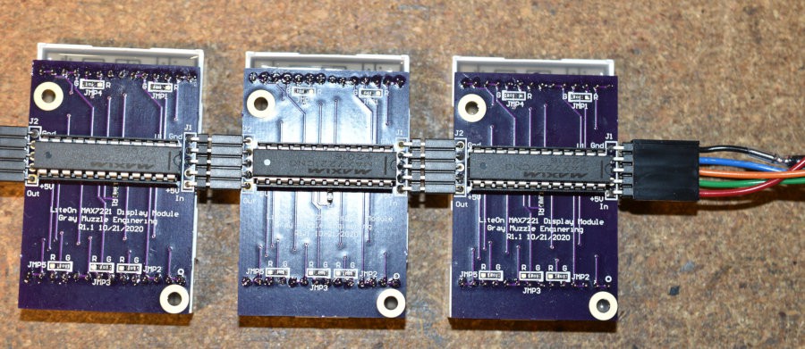
In the picture above, the Raspberry Pi is connected to the cable at the right end of the 3 modules. Note the In and Out labels on the boards below the connector.
Details of a SPI Transaction
The following description of a SPI transaction refers to the most common configuration called Mode 0 that is used by the MAX7221 and should be accepted by the MAX7219 chips. Other Mode configurations result in different timing relationships between the SCLK and the MOSI signals and the CS signal may be inverted from what is described here.
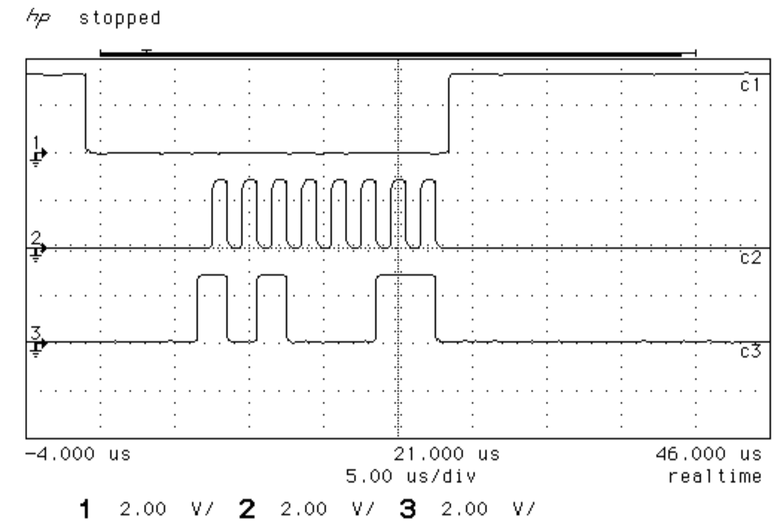
In the scope shot above, the picture starts with the Chip Select (CS) signal high and the Serial Clock (SCLK) signal is inactive. The value of the MOSI signal does not matter while the CS signal is high and the SCLK inactive. The falling edge of the CS signal is the start of the SPI transaction. This transaction is sending the hex value of A3 or binary 1010 0011. The Most Significant Bit (bit...
Read more » Bharbour
 Andrew Tudoroi
 sjm4306
 Dorijan
 Mike Szczys