Arduino UNO Pinout and Board description
I will explain the description of the Arduino UNO Pins and the board in the post. Arduino Uno is a standard board of the company, even though other boards e, g. micro, Nano, mega, Leonardo, 101. Due and Yen. Arduino also manufactured IoT (internet of things), Bluetooth, GSM/3G, Wi-Fi, and motion sensors boards.Arduino Uno board
The Atmega328P Microcontroller is an 8bit with 32k byte internal flash memory. To program the main chip, a 16 MHz crystal is part of the board. The Arduino board requires only 5V DC to operate.
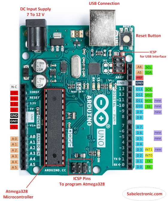
Arduino Pins color shows pin functions. Blue color represents Power pins, Pink for analog input pins, Light blue for Digital pins, Green for communication, and Purple for PWM pins.
FIG-A
Arduino Uno pins detail
Arduino UNO board has analog/digital (PWM) pins. These pins could be GPIO or using for specific signals.
Vin Pin
It uses Vin pin for 7-12 VDC apply to the board as an external power source. We can use a 9V battery cell for the input supply voltage.
Analog Input Pins
Pin A0 to A5 Used as analog input pins (for Sensors modules) used as analog output. It contains 06 ADC (analog-to-digital converter)with a 10-bit resolution. These Arduino pins have the functionality of general-purpose digital in/out pins.
SDA/SCL
We use it for I²C (inter integrated-circuit) / TWI (two-wire interface) communication. A Wire library is available to communicate with different devices with the Arduino board.
Serial-UART (SPI Communication)
Pin 0 used as RX and 1 TX (in fig-A as D0&D1)used for TTL Serial Communication. RX is to receive data, and TX to transmit the data.
SPI Communication pins
10 (SS), 11 (MOSI), 12 (MISO), 13 (SCK). These pins support SPI communication.
Interrupt
Pin 2 & 3 can use as INT0 & INT1, we can configure it to act as external interrupts for a function written in the program.
PWM
Pin # 3, 5, 6, 9, 10, and 11 used for PWM function (Pulse Width Modulation). Analogwrite function () is very effective to operate the DC motors and varying led light in many electronic projects.
AREF Pin
We use an analog reference pin for analog reference. AREF is used to set external analog input voltage. We cannot use less than o and over 5 volts for the AREF Pin.
Arduino Uno Pins(GPIO)
We use 14 digital pins as input or output. From 0 to 13 used as general-purpose digital in/out has internal pull-up resistors that can be high/low to ON/OFF maximum current per pin 40 mA.
As showing in fig A from D0 to D13 pins. A built-in led function through pin 14 (D13).
PWM (Pulse Width Modulation)
We use digital out as High or Low even with PWM outputs function. We can use these pins, As analog out/we can control the motor at different speeds. Digital write() function used for high/low pins.
USB Communication Interface
For USB/Serial communication, we use mostly two chips, CH341A or Atmega16U.
CH341A
CH341a has used a USB interface chip for UART communication, It is a standard parallel port, memory parallel port, and synchronous serial (I2C, SPI Communication). We use the CH341A chip in many cheap programmers.
Atmega16U
We use atmega16u Microcontroller for USB serial communication interface. To program the Microcontroller, an ICSP pin header is available on the board.
LM358
LM358 is a dual-channel op-amp IC. In Arduino, used for an auto-voltage selection circuit, but in reality, it operates as an auto...
Read more » Shahbaz
