Sasha Shturma
-
Week N. Sharing is caring
07/26/2021 at 03:00 • 1 commentAfter a long pause, I was finally able to get my hands on the project again. After some polishing, the design files are now ready to see the world:
https://github.com/renetec-io/cm4-panel-jdi-lt070me05000
Enjoy!
-
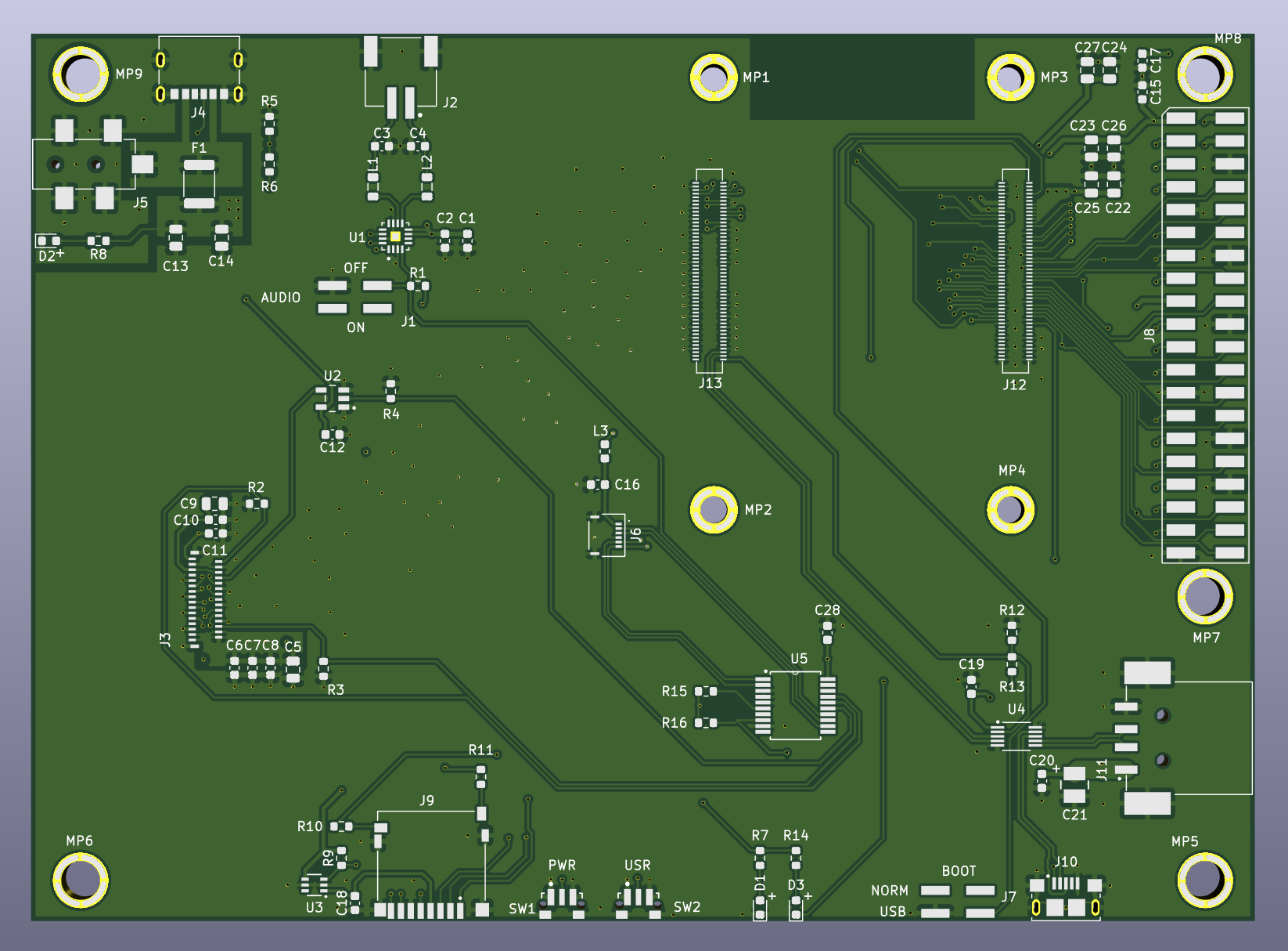
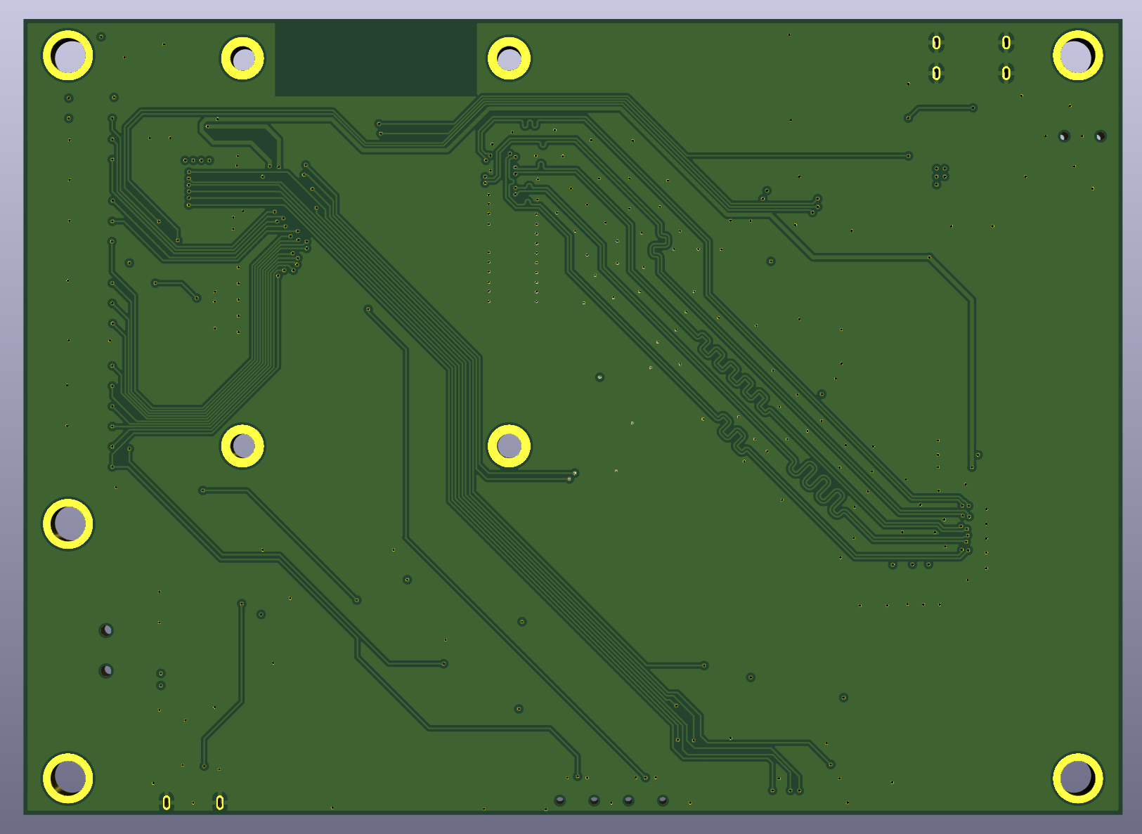
Week 12. New PCBs sent into production
02/22/2021 at 05:01 • 5 comments![]()
![]()
-
Week 11. Working on PCB Rev. 2
02/15/2021 at 19:15 • 0 commentsNow finishing the board design in KiCad. I will share the project in the end after it is tested. The list of changes is under "Read more" link.
Meanwhile, check out my tutorial on DIY PCB assembly here:
Instructables: How to Assemble a PCB With Tiny SMD Parts
---------- more ----------- Changed GPIO expander from SX1508B to MCP23008T, which is supported without rebuilding the kernel.
- Selected more DIY-friendly IC packages for the expander and the USB switch.
- Corrected board dimensions to exactly match the display.
- Removed unnecessary 0-ohm jumpers.
- Added capacitors near host USB connector.
-
Week 10. Touch and sound are now working.
02/09/2021 at 03:10 • 0 comments -
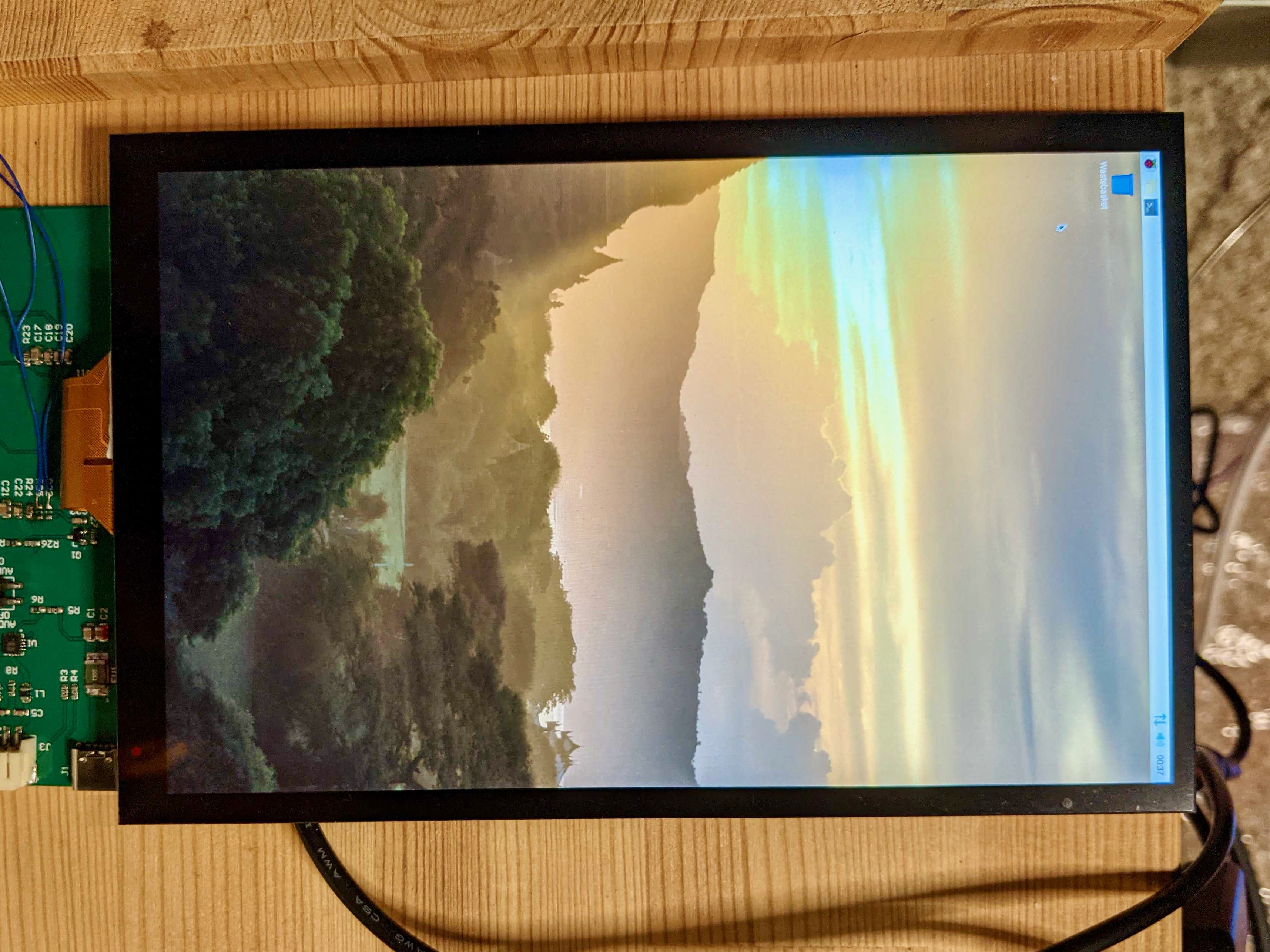
Week 9. Software stabilized.
01/31/2021 at 04:34 • 0 commentsIt looks like we got it working reliably now. As I promised in the last update, sharing the details of our software bring-up struggle, click "Read more" below the image if interested.
![]() ---------- more ----------
---------- more ----------Whatever you do, someone has already done that before. LT070ME05000 bring-up is not an exception. There are two great discussions to follow on the Raspberry Pi forum: [SOLVED] DSI Panel JDI LT070ME05000 bringup issues and VC4 Video Driver dont start DSI Interface. Many thanks to Raspberry Pi Foundation engineers that are willing to offer their help with the issues along the way. For someone, the Nexus 7 driver just worked out of the box: GitHub: harlab / CM4_LCD_LT070ME05000. We are not that lucky.
What we have learned:
- Working with a custom DSI panel requires the Full KMS mode GPU driver, which is being in active development and only works with changes from kernel version 5.10+. Currently, the official stable version for RPi is 5.4. We had to update the kernel ahead of its official stable release.
- As we use the I2C GPIO expander to save user GPIOs, we needed a kernel driver for it. The driver exists but apparently cannot be built with DKMS as it is using some unexported kernel functions and needs to be built with the kernel. That is unfortunate because it means maintaining our own kernel builds just for this driver. We are considering another expander (MCP23008) for the next PCB revision. That one seems to be supported by default.
- The display panel driver also needs to be enabled in the kernel build configuration, but this one can be built with DKMS and automatically re-built on every kernel upgrade.
- The biggest surprise: there are counterfeit display panels out there! This is really interesting. The panels that we received as samples from a Chinese supplier require some changes to the initialization sequence found with trial-and-error. They don't strictly follow what is written in the datasheet and require the "exit sleep mode" command after the "set display on" command, while in the datasheet (and the mainline driver), it is the other way around. Even after fully enabling the panel, a sleep mode flag in the power mode register tells us it is still "sleeping," which doesn't make sense. I ordered a repair kit for Nexus 7 from Amazon to get a different panel sample under the same part number for comparison. That one worked as specified. Another interesting detail to notice - there is no serial number (which is supposed to encode revision, manufacturing time, and location) etched on our samples. This makes me think there is a non-authentic version of this panel that is used in some tablets for the internal Chinese market. That is just my assumption. The display still works fine, but the driver requires some changes to the initialization procedure.
- Another surprise: the driver is not properly turning the panel off before the signal disappears when the software blanks the screen. When this happens, something gets seriously screwed up between the panel driver IC and the LCD matrix. It then results in persistent visual artifacts and screen flickering that takes hours to dissipate. Powering the poor thing down does not fix that. It looks like it is under control now with our latest driver changes.
That is it for now. It seems to work reliably, but our fingers are crossed in the hope not to run into another issue soon. The next step will be to enable touch input. It is supposed to be trivial, but who knows.
-
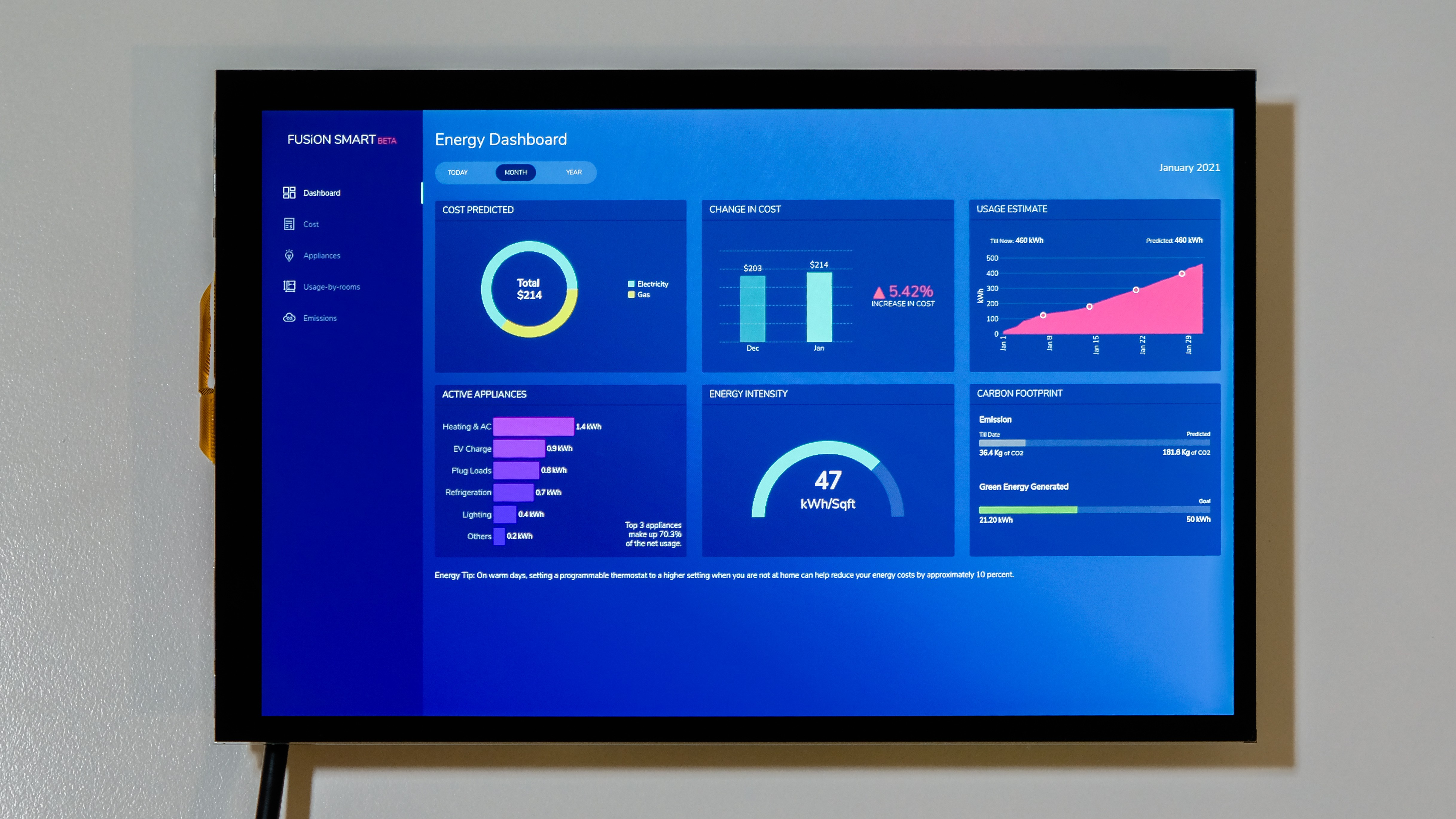
Week 8. It is up and running!
01/24/2021 at 02:12 • 0 comments![]()
We got the image. Still, there is work to do, I will share the details later.
-
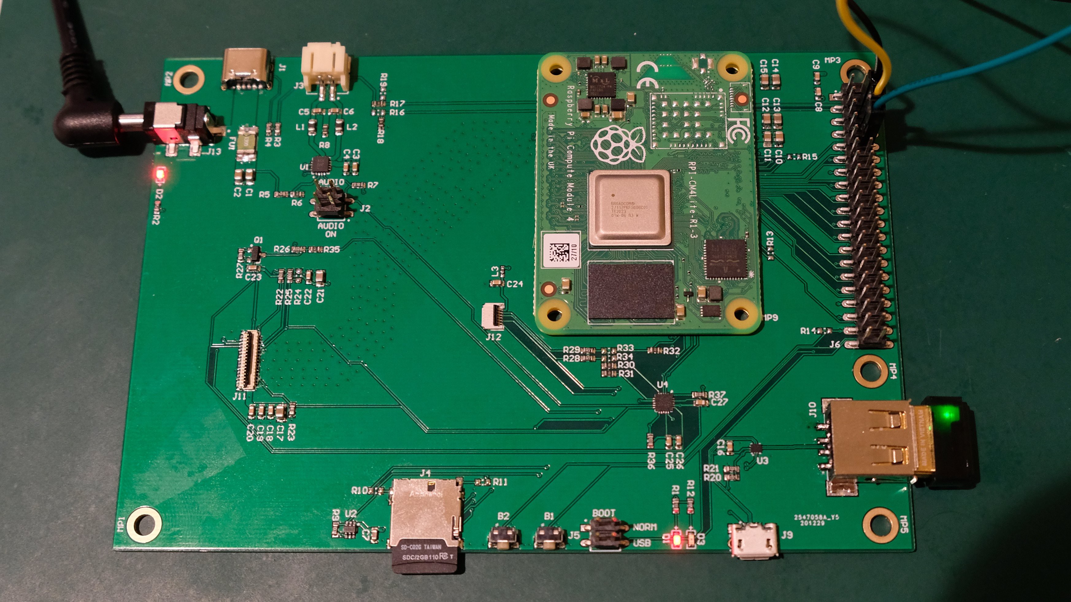
Week 7. Ready for bring-up.
01/19/2021 at 08:12 • 1 commentAssembled the board, the next challenge is software.
![]() ---------- more ----------
---------- more ----------There is a chance the display will just magically work with existing DSI kernel drivers and panel drivers from Nexus 7 bring-up back in the days. There is an interesting and inspiring thread on Raspberry Pi forum, https://www.raspberrypi.org/forums/viewtopic.php?t=253912. The topic starter was doing the same bring-up with CM3+, and eventually, he succeeded. The new parameter to the equation is the difference between BCM2837 and BCM2711. Also, the DRM stack is in constant development by Raspberry Pi Foundation, and what worked just yesterday may no longer work with after the latest update. We will see.
-
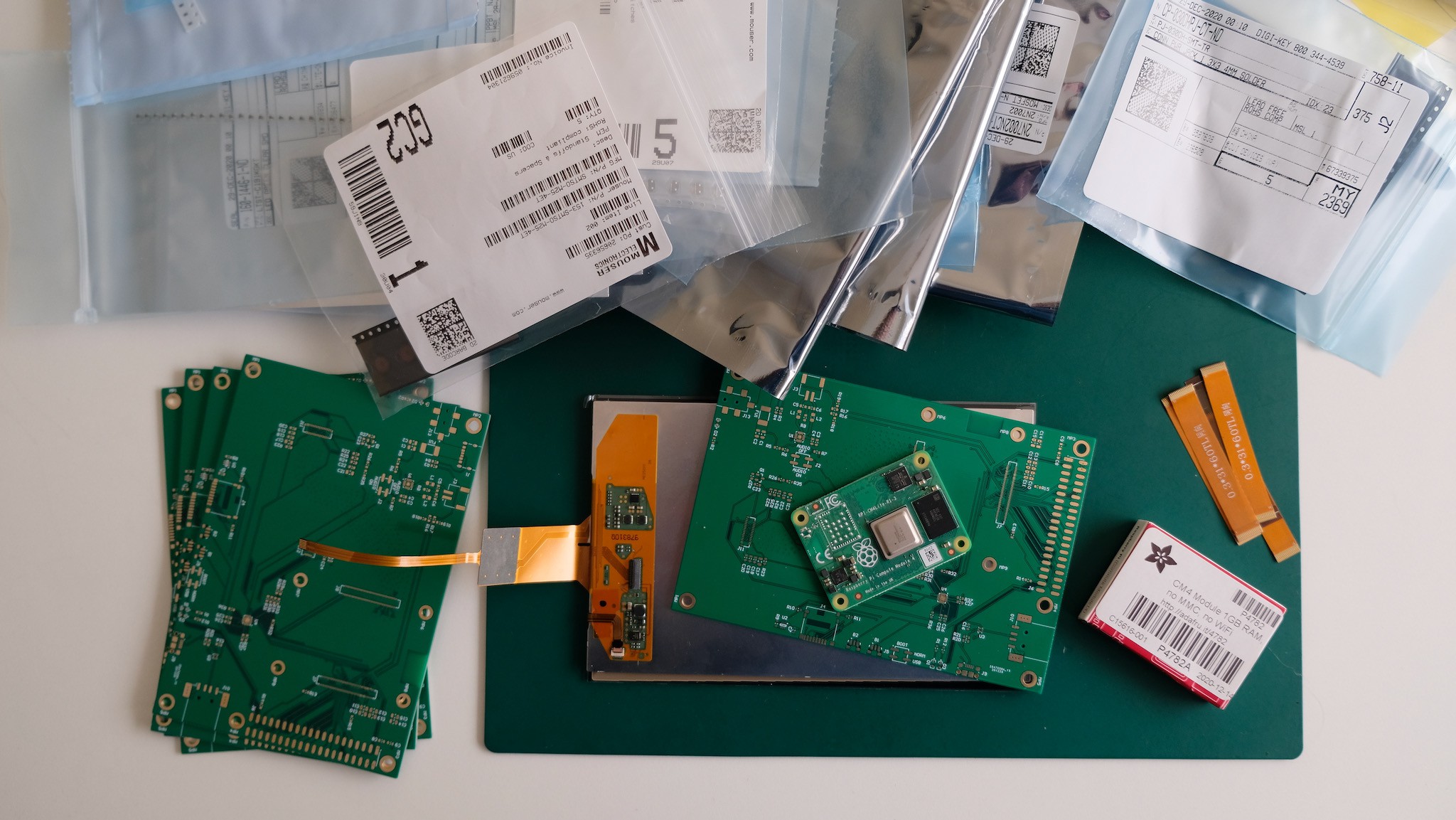
Week 6. Getting ready to put the hardware together.
01/11/2021 at 05:09 • 0 commentsEverything has now arrived: PCBs, displays, compute modules, components. Time to get hands dirty with the solder paste.
![]()
-
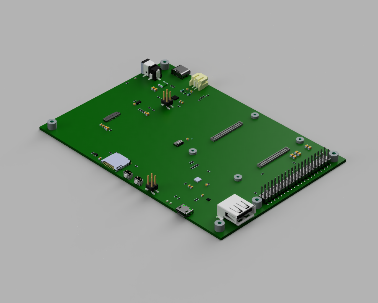
Week 5. PCBs ordered.
01/05/2021 at 19:36 • 1 commentAn exciting milestone in the project was achieved right before New Year's Eve: the design is finished for the first PCB revision, time to order the boards.
---------- more ----------We ordered bare boards (no assembly) and STM stencil from JLCPCB in China. We will solder a couple of initial prototypes ourselves, and it is going to be fun. I expect that CM4 connectors may be challenging for manual soldering. We will see.
A spoiler for the next update. PCBs are already on their way from China.
![]()
-
Week 4. The board architecture is finalized.
12/29/2020 at 03:21 • 2 commentsWe are now done with the architecture, BOM, and most of the schematic.
---------- more ----------Our display panel's good thing is that it has all power circuits on-board, including the backlight driver. That saves us a few bucks on bucks, pun intended. BTW, Raspberry Pi CM4 also has its voltage converter on-board now. The power architecture will be very straightforward, unlike in our previous board with CM3+ and a different display.
The unpleasant surprise in the CM4 is that there are no additional GPIO pins available on top of those 28 that are exposed on the 40-pin header of regular Raspberry Pi boards. We want to preserve the header untacked, but that means we don't have any lines to use for controlling LCD and touch driver ICs. At least, there is still the I2C bus 0 available to us. We will use GPIO expander with I2C interface to partially mitigate the GPIO shortage. There is a nice SX1508B expander from Semtech with software support in the Linux kernel. It also has two separate power domains for 3.3V and 1.8V, which helps us avoid additional level shifting. Nevertheless, we are still reserving two pins, specifically GPIO 16 and 17, for time-sensitive things like the touch-sensor interrupt line and the "tearing effect" line (a vertical synchronization for the framebuffer to avoid the tearing).
The next step will be to finalize the schematic and order all the components for the first prototype.
Raspberry Pi CM4 Сarrier with Hi-Res MIPI Display
An interface breakout board for Raspberry Pi Compute Module 4, permanently attached to a 7" IPS touchscreen display