 David Tucker
So in my quest to engrave pocket hugs faster we already talked about upping the line step and how that has really only one proper setting. You can get quite a speedup with this, but you sacrifice a lot of quality in the process. The other way to speed things up is to bump up the speed the laser can scan at. This has the advantage of not significantly effecting quality (up to a point) but there are hard upper limits on this.
For starters if you double the speed you need to also double the engraving power to get the same power per mm. In the case of my N40630 5w module I'm already pushing the power about as far as I can. I could possibly engrave a bit faster, I will experiment with it, however I need my 4x stronger A40640 10w module to really benefit from this.
I experimented with bumping up the x axis velocity but quickly ran into a hard upper limit of 4,000 mm/min, at that rate I get a hard fault and the system stops running. My power supply is a 24 volt 3 amp unit, I have often wondered if this was strong enough. I'm using 4 stepper motors (5 with the rotary) and each is setup at around 1.5a power. In my mind that would require a 7.5 amp supply. However I found this article from Gecko Drive that says you need a power supply that is rated for 1/3 the amperage of the stepper. In that case my 3 amp supply is plenty since all steppers activated would only use 2.5 amps. They also give some interesting torque/power curves that suggest going with a higher voltage can in fact give you more torque at medium speeds, but no matter how strong the torque eventually falls off as speed increases.
I'm already running a 24v, and the drivers I'm using only go up to 28v so there is no real potential for bumping up the voltage. That leaves the amperage. To test out if I need a larger supply I pulled all the stepper motor drivers from my machine but the x axis. That way no power is being used by the drivers or motors and all the current is available just for the single x axis motor and driver. Repeating my tests I still had the same failure at 4,000 mm/min. So amperage is not the problem.
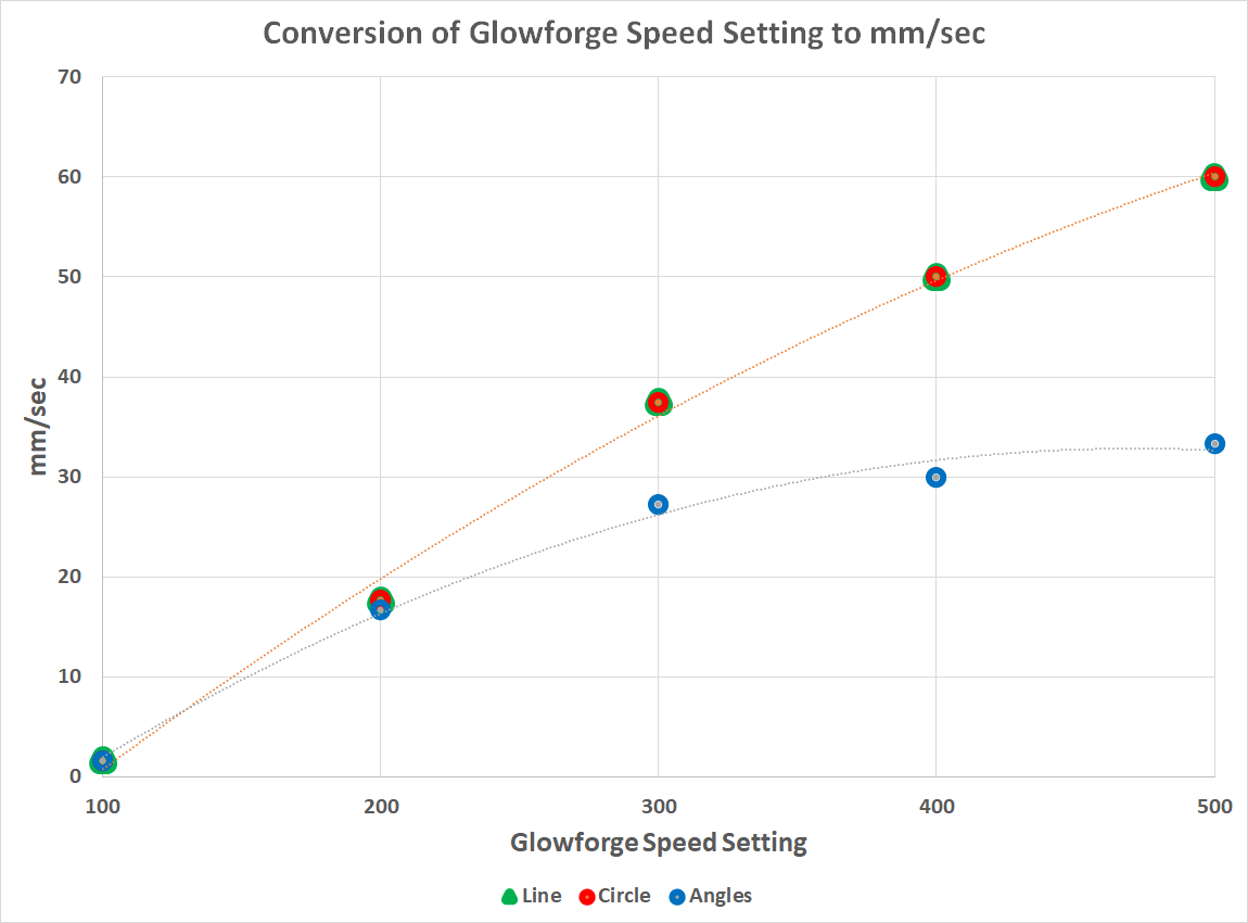
Another idea is that the arduino micro controller just cant keep up with number of steps required to run at these rates. My X axis takes 25 steps per mm, but with 16x micro stepping that is bumped up to 400 steps per mm. Running at 4,000 mm/min or 66 mm/sec that works out to around a 25 kHz step rate. The rumor is that an arduino could in theory run at 100 kHz step rate but things like interrupt handling may not be able to keep up at even 30 kHz. To test this theory out I pulled all the jumpers from my stepper, leaving it in 8 micro step mode. A quick tweak to the firmware to let it know about the change and I was able to run the X axis at speeds up to 7500 mm/min (125 mm/sec). So we found the culprit and I can in fact run my axis faster. However this comes with two catches. First the faster we go the more acceleration plays a role. That means that running at 6,000 mm/sec is not 2x as fast as running at 3,000 mm/sec over the full travel of the move because the start and finish of motion must begin at 0 and accelerate up to full speed. You can see this very clearly in this image from the Glowforge forum where they compare the actual speed of a 300 mm long cut using a straight line vs a series of 50 mm jogs in x and y. As they try to push the top speed up there is a point where acceleration overwhelms everything and there is little to no benefit to running faster.
We can play around with acceleration settings but eventually we will run into issues with lost steps when making small rapid motions, the same goes for jerk settings. Still it is something to play around with.
The other problem is that the stepper motors are not stable through there full range of speeds. Mine have an annoying resonance at around 3,500 mm/min. Running faster than that gives me smooth motion, but passing through that speed can result in a jarring sound and presumably unstable motion as well. This highlights a third closely related problem. These high speeds are fine for long linear motion but if we were trying to run at these speeds while tracing a complex shape we would most likely get oscillation when we have to rapidly change directions, like when cutting a square corner. And of course these speeds are not suitable at all for milling with a spindle. The motor torque is lowered at higher speeds and we would certainly miss steps, even if our spindle was capable of handling the speeds.
It would be nice to know what other machines manage to run at, that is a good way for us to estimate if we are in the ballpark or not. I did some digging around to find recommendations for various CO2 laser machines. I'm seeing numbers in the 100 mm/s to 300 mm/s range for the most part. That is 6,000 mm/min to 18,000 mm/min. Were never going to get up to 18,000 mm/min with this heavy laser diode on the end of a z axis but we could possibly hit the 6,000 mm/min range. Honestly I'm very suspicious of that 350 mm/s number, not that the machine can't be asked to run that fast, but that it has much impact on the real world speed, ie that the laser head can actually accelerate fast enough to achieve the speed it was asked to travel at.
I came across another note from a laser manufacturer that suggested that CO2 lasers can't really cycle faster than about once every millisecond. If your trying to hit a 0.1mm dot size that limits you to about 100 mm/sec for the top speed, 200 mm/sec if your going for a 0.2mm spot size (more realistic with a CO2 laser). You can of course go faster but your resolution will drop. And of course a CO2 laser has a larger dot size than a diode laser so they can run faster in the Y direction as well, but a diode laser will have an ability to engrave at a finer resolution.
Anyway I need to go back to the garage and actually try engraving at faster speeds to see if the laser can keep up and the motion is stable. I won't really be able to dig into this fully until I get my new laser module, but it has some serious potential to speed things up.
---
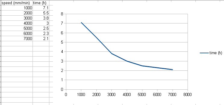
Here is a comparison of estimated run times (in hours) for engraving my project at 0.1 mm line spacing and varying the top speed from 1,000 mm/min to 7,000 mm/min using the current acceleration values for my machine. You can see that as we get above 4,000 mm/min the acceleration starts to overwhelm the process and the gains rapidly diminish with only a 30% decrease in time when going from 4,000 to (estimated) 8,000 mm/min. Note that doubling the acceleration only drops the run time by a small amount, there is more going on here than just the x axis travel.
---
I went ahead and pulled all the jumpers off of my x and y stepper motors, lowering there micro stepping from 16 to 8 (from 400 steps per mm to 200 steps per mm). This keeps my x and y axis using the same resolution. I left the Z at 400 micro steps but it probably could be lowered as well.
While I was testing everything out I noticed that a few of my clamps and backlash nuts on my lead screws had loosened up a bit. A quick bit of tuning things up and I was able to get rid of a lot of the resonance at 3,500 mm/min speeds.
In the end after some playing around I settled on a max speed of 6,000 mm/min in x and y with an acceleration of 200 mm/sec^2. This seems stable and yet does not over exert the machine. That is only good for doing a scan over a large area. Trying to do a vector cut at 2,000 mm/min caused some stability issues when doing rapid changes in direction. It is possible that I could tune this out by lowering acceleration, but that reduces the benefits of the higher speeds. For now I will leave it like this and just manually limit the speed of vector cuts to 1,000 mm/min or lower.
My birthday is on Wednesday, I cant wait to try out my new laser module and see what it really can do.
Discussions
Become a Hackaday.io Member
Create an account to leave a comment. Already have an account? Log In.