David Tucker
-
bear down
07/14/2021 at 04:52 • 0 commentsSo I'm thinking more about the idea of a rotary attachment. One part to work out is what step resolution we need.
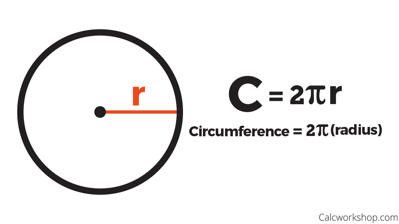
![]()
If the maximum diameter object we could ever machine is 90 mm then doing a bit of math we can work out that the circumference of that object is 3.14 * 90 mm = 283 mm. If we used a smaller object the circumference would be reduced as well. For example a 30 mm diameter would give us only a 94 mm circumference.
Our existing linear axis has a full step resolution of 25 steps per mm, with 16x micro stepping that is increased to 400 steps per mm, but we probably don't retain anywhere close to that resolution between errors caused by backlash, flex, and inconsistencies in the micro stepping.
The stepper motors we are using are standard NEMA 17 motors with 1.8 degrees per step. Again with the math that is 360 deg per rotation / 1.8 deg per step= 200 steps per rotation. With 16x micro stepping that is increased to 3200 steps per rotation.
If we don't use any gear reduction then at 90 mm diameter we would have a resolution of 200 steps / 283 mm = 0.71 steps per mm, with micro stepping that is increased to 3200 steps / 283 mm = 11.3 steps per mm. Compared to the x/y resolution this is 35x lower resolution!
To match the X/Y resolution we can use a 35:1 gear reduction, that will take something like a worm gear or planetary gear to achieve, and it may not be worth it if there is too much backlash in the system. More than 0.05 degrees of motion would nullify any benefits, that would take some tight tolerances.
We could use a belt drive, that is a popular choice. The largest off the shelf belt drive setup I could find was 60:20 teeth or a 3:1 reduction. That would increase our steps per mm from 0.71 to 2.1. That is still 12x lower resolution than the X/Y axis but it is better than the default. Again we need the belt to have relatively low backlash and flex or the benefits are lost.
If we just focus on lasers then we need a minimum of 0.1 mm resolution to ensure that we can draw one laser line directly next to another (assuming a 0.1 mm kerf). Doing a bit of math that requires a 14:1 reduction if we are trying to use full steps, If we rely on the 16x micro stepping then we don't need any gear reduction at all, but that assumes 16x micro stepping is really 16x, chances are that is a bit of a stretch.
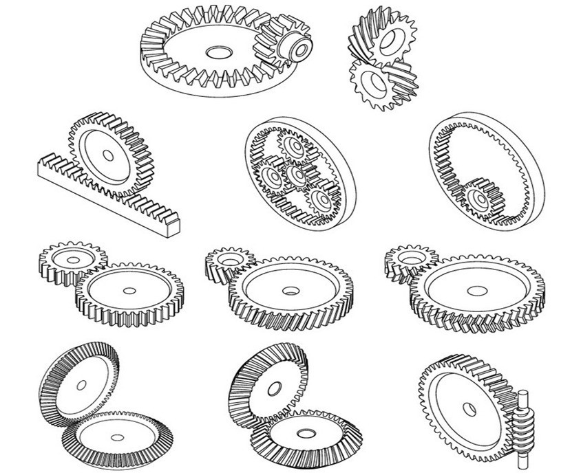
![]()
There are many different types of gear reductions we can use.
- The obvious candidates are a toothed belt drive or standard spur gear setup. These both can be 3D printed (minus the belt) and could easily be built into our support structure. On the down side the reduction is low if we don't chain gears together, probably no higher than 4:1. In addition it can be difficult to control backlash, especially with 3D printed parts.
- A worm gear is a great candidate. They can have much higher gear ratios (14:1 is easily achievable), and the backlash is relatively low. By using a duplex style worm we can adjust out the backlash completely, at the cost of some additional friction. But since we are not moving quickly the friction is probably not a big deal. On the downside the worm gear has higher friction, the gears are not as simple to print as a spur gear, the setup can't be back driven, and the motor needs to be set at a right angle to the chuck.
- A planetary gear will also give us a large reduction with minimal backlash. However there is even more friction (and more backlash) in this setup. The big benefit to a planetary setup is that it can be made very compactly. We don't need that in this case.
- In the more extreme and exiting we can use a cycloidal drive, also known as a wobble drive. These have a high contact area so they are relatively strong. However you need many bearings to make it work smoothly.
- Finally we have the truly wacky harmonic drive also known as strain wave gearing. This also has a large gear reduction, low backlash and a relatively compact design. The problem again is that we need quite a few bearings to make it run smoothly. This is very intergang but it requires relatively close tolerances to make it work. On the upside we can get very high gear reductions with almost no backlash.
Anyway this is just exploratory work, there is still quite a bit left to go.
-
Round-a-bout
07/10/2021 at 05:36 • 0 commentsI have been thinking about adding a rotary axis for a long time. It could be used with the laser to carve pictures into water bottles or other round objects, and with the mill to make round or complex shapes that are milled on 4 faces.
If I remove the spoiler board I have around 90 mm of Z height between the floor of the machine and the bottom of the Y carriage. I could just barely fit a 3" chuck in that space (when fully opened). However the cheapest 3" chuck I can find cost just a bit over $50 and that is a lot to pay for a low cost 3D printed router.
![]()
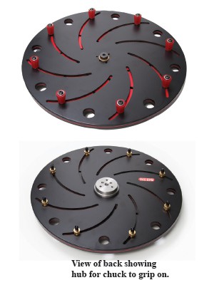
I could pick up or make a longworth style chuck. This is made out of two flat pieces of material and could easily be 3D printed. However the jaws on this chuck don't grip very well and it is really made for much larger material than the 90 mm we have to work with.
![]()
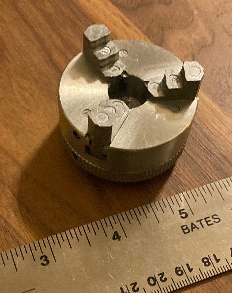
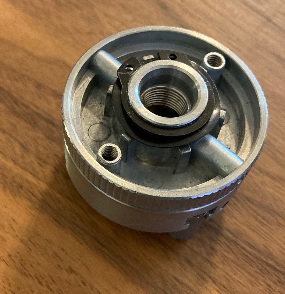
So a while back I ordered a small 2" chuck (48 mm) from Amazon for $12. This is made out of some cheap cast material and is very stiff but after taking a file to it I managed to free it up enough to work. It has a clamp diameter between 2mm and 65mm depending on how you arrange the jaws and if you are clamping on the inside or outside.
![]()
It takes a 12 mm center bolt, or two 4 mm bolts on the back side for mounting. It is good enough but not a great chuck. I wanted to see how it would work, and to use it as a template for a larger 3D printed chuck at some point in time in the future.
Anyway this is still just in the initial planning stage. I need to work out either how to swap the Y axis stepper with the new A axis rotary stepper, or I need a new 5 axis controller and a 5 axis version of GRBL or Marlin to go with it. Still it has some promise, at least it will be educational.
-
Micro Stepping
07/10/2021 at 04:46 • 0 commentsI came across an interesting blogger, Jim from Jim's Embeddedtronics. There are lots of interesting posts in here, but I wanted to highlight one. He has a machine to measure torque of a stepper motor at speed and he ran a series of tests on micro stepping.
The end result is simple enough, micro stepping does not reduce the torque of your stepper motor but rather it helps smooth out the motion of the motor. I had run a somewhat similar test a while back and came to the same conclusion, but it is nice to see it verified with better equipment than a postal scale.
There is a lot of confusion about this online with people assuming that if you run 1/16 micro stepping you end up with 1/16 the holding torque. The truth is that when the stepper is on a full step the holding torque is at full force. And when the stepper is half way between poles (half step) the torque is reduced by 30% or so. However as you push the rotor closer to a pole (full step) the holding force increases. So micro stepping can't necessarily hold position accurately between the poles but it can't reduce the accuracy any lower than without micro stepping.
Basically it is a win-win, when the motor is not pushed to its limit it increases accuracy and smooths out the motion. But when the motor is pushed to its limit it works as good as if you had no micro stepping at all. Basically, as usual, whatever you read online is probably wrong, to some extent.
-
Plane and simple
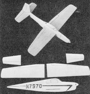
07/07/2021 at 05:28 • 0 commentsI was casting around for a project to try with the laser and I hit on making a small balsa wood glider. I came across this website with plans from an old issue of American Aircraft Modeler for two different balsa wood plains.
![]()
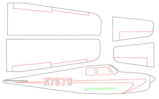
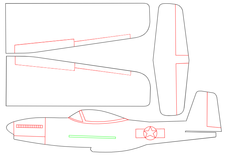
These use 1/16" wood for the wings, and 1/4" thick wood for the body. The original plans call for a piece of each that is 3"x3' but I don't think you need that much wood. Anyway I took the liberty of tracing the plans they provided in inkscape and have posted them here. I think this is ok since the plans are out of print and the page is already posted to the internet. However the original author still holds the copywrite, so don't try to sell these.
![]()
![]()
I need to go down to the hardware store tomorrow and pick up some wood, but I think these will turn out good.
-
Measuring the kerf
07/03/2021 at 03:57 • 0 commentsMatthias at WoodGears.ca ran an interesting experiment a while back. He used a simple test file to measure the kerf width when cutting with a laser. The idea is to cut fingers out of a part, and then by using a dial indicator we can measure how much slop there is between the parts. In addition he flips one half of the part over to get a rough measure of how much taper there is to the kerf. Or more exactly to measure how close to the center of the piece the focal point is.
He later had another user re-run the test with a better calibrated laser, this really shows the genius of his test. The new machine is not only cutting sharper, with less angle on the cut but the cut is much cleaner as well with minimal scorching.
Anyway this is a really neat idea, I will try to replicate it on my machine.
-
Know your limits
06/30/2021 at 02:26 • 0 commentsI love my project and I would love to see everyone try to build a machine just like mine. However I have seen several people build it and struggle with one part of the build or another. I wanted to drop a note to call attention to how complex of a build this is (or any home built machine). You need skills in electronics, programming, mechanics and a good eye for detail as well.
In particular while I have worked hard to simplify the mechanical build as much as possible the electronics and software remain quite complex. No one that I know of has put together a CNC controller in a box type setup where all the fiddly details are taken care of for you. It would be a great addition to the community if someone could come up with that solution. This is one really nice aspect of buying a commercial kit, the software and electronics are taken care of and you don't need to understand how they work.
I don't want to discourage anyone, just set realistic expectations. It may take some time to build up the skills to complete the full build. You may want to start small and put together a 3D printer kit, or mess around with an arduino for a few weeks. It is an achievable project, but it is not a small one. Be kind to your sanity and start this project with your eyes wide open.
-
Focused-er
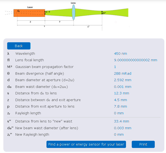
06/27/2021 at 20:43 • 0 commentsUsing the numbers from my last post, I plugged them into a focus spot calculator and came up with the following outputs.
![]()
With a short focus distance we end up with a thinner waist (spot size) at the focus point, but a faster converging beam, so we get a finer spot for etching, but a thicker kerf for cutting.
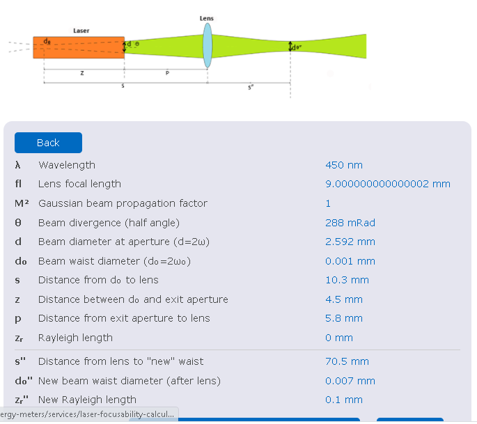
![]()
With a longer focal distance the properties reverse with a thicker spot size and a thinner beam convergence, so better cutting performance and poorer engraving performance.
Keep in mind that I'm not 100% certain on most of these parameters so these are just rough approximations and could be totally wrong.
-
Focused
06/27/2021 at 00:16 • 0 commentsI have been trying to work out the math behind how a laser diode is focused. There is a lot of talk out there about what lens or focal distance works best but I'm struggling to find any actual hard proof of how it all works. It seems to me that if one focal length works better than another that we should be able to prove it mathematically.
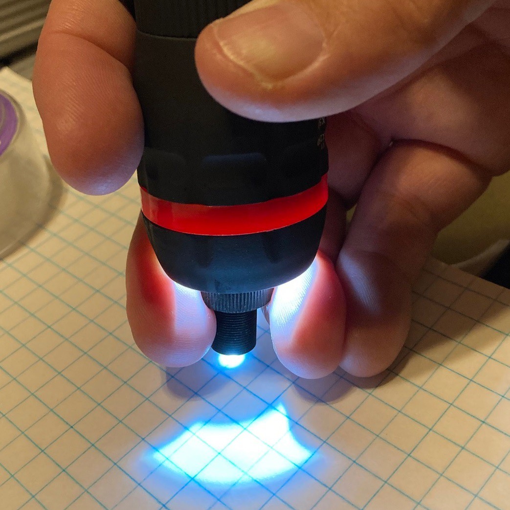
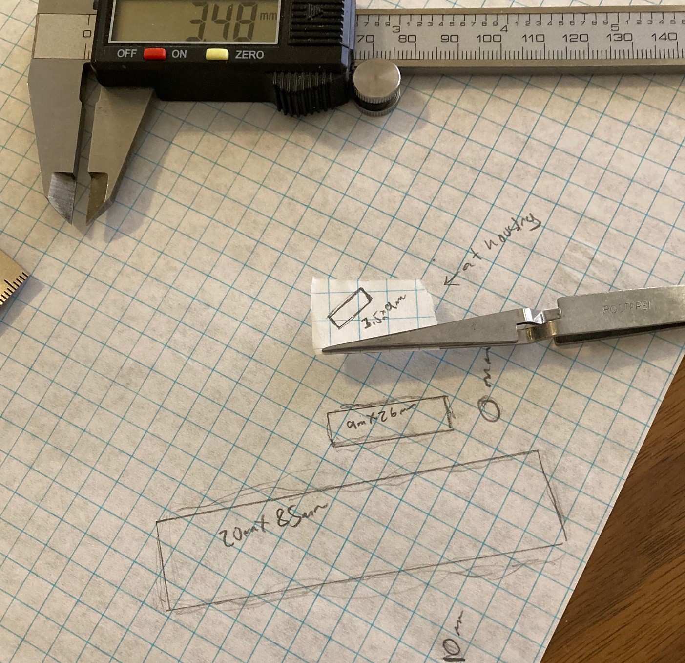
I came across a writeup on Gaussian laser focus, and another on Math behind a collimating lens. In order to follow the equations we need to measure some details on our lasers. First up was the focal length of the lens.
![]()
This is a single element convex glass lens that is about 6 mm in diameter and 1.5 mm thick. To measure the focal length of the lens I shined a flashlight through the lens and focused the resulting light at a piece of paper. By measuring the distance to the paper, as well as how deep the lens is in the holder we can work out the final focal length. In this case I measured it at around 7 mm, give or take a mm. It is not clear in the image above because it is blown out, but the focal point is only a pinprick.
![]()
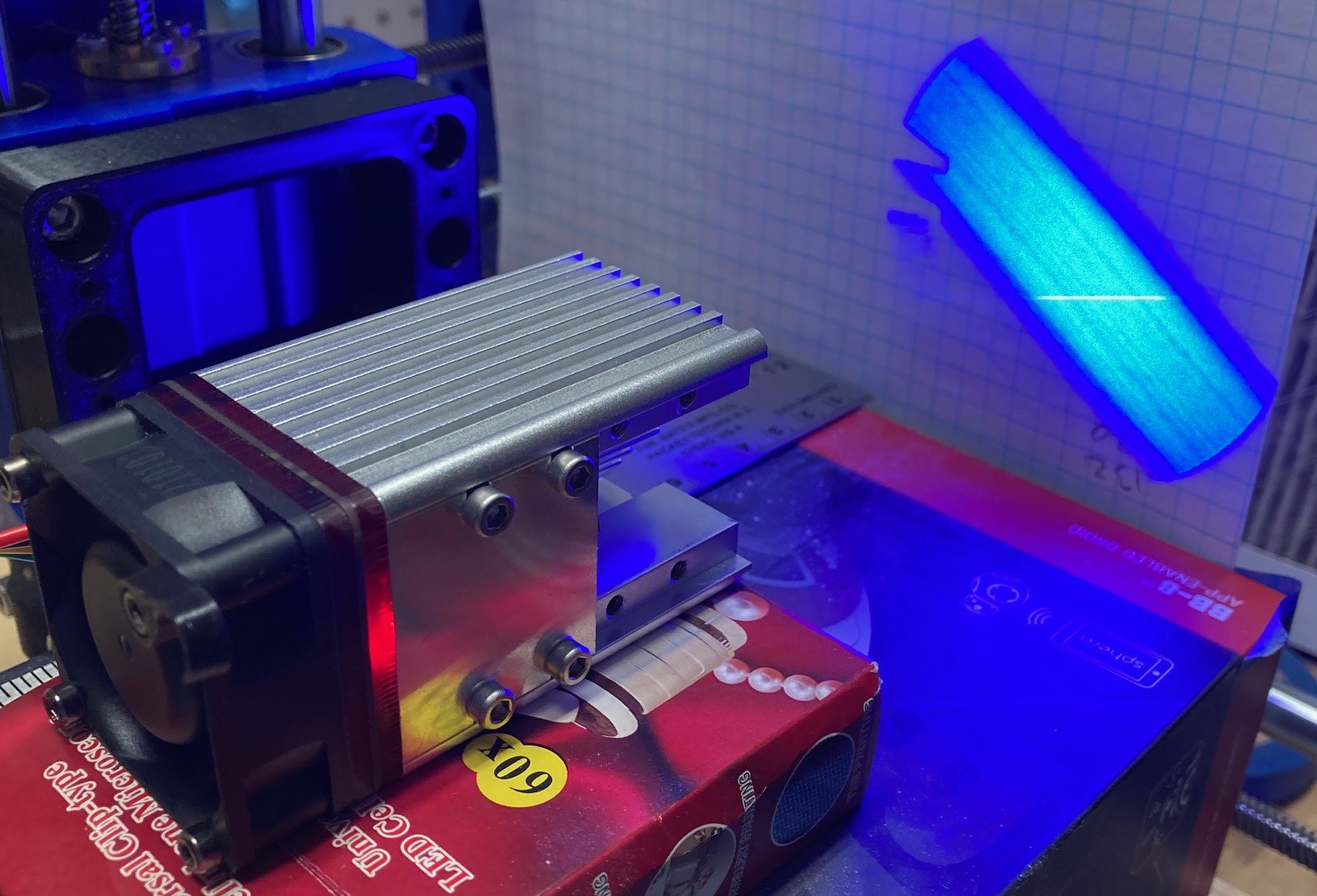
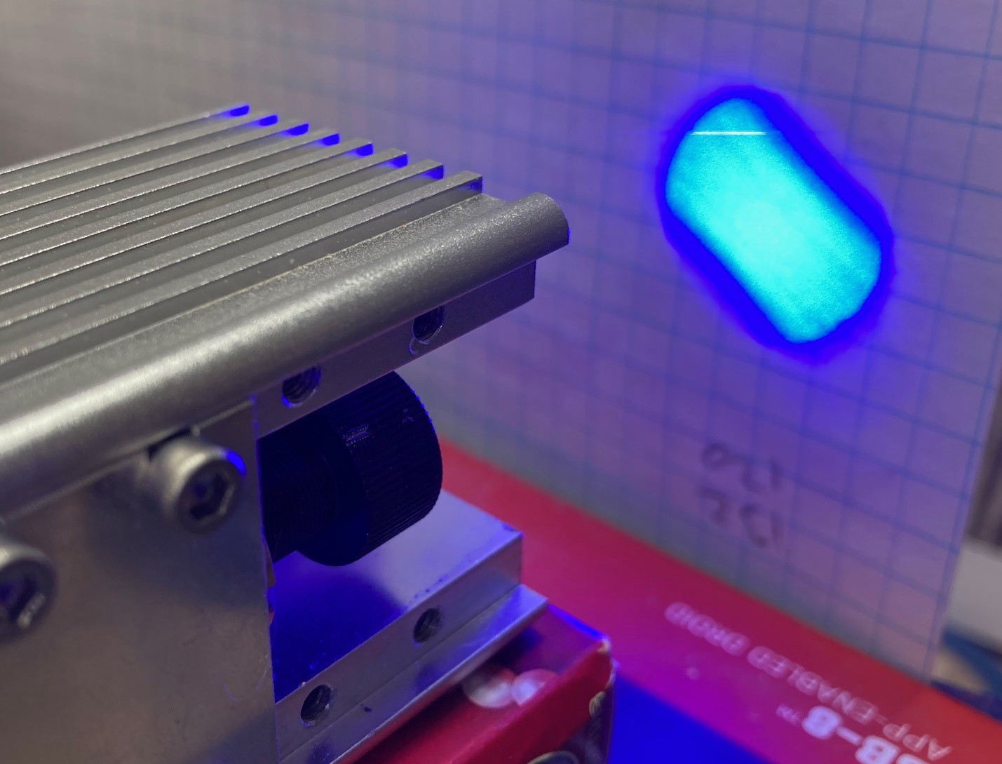
Next I wanted to work out the angle of divergence of the laser diode. I removed the lens and shined the laser at a piece of paper at fixed distances and then used a marker to outline the shape of the beam. I did this at 100 mm from the base of the silver housing, 0 mm from the base of the silver housing, and right at the end of the brass tube that the lens fits into.
![]()
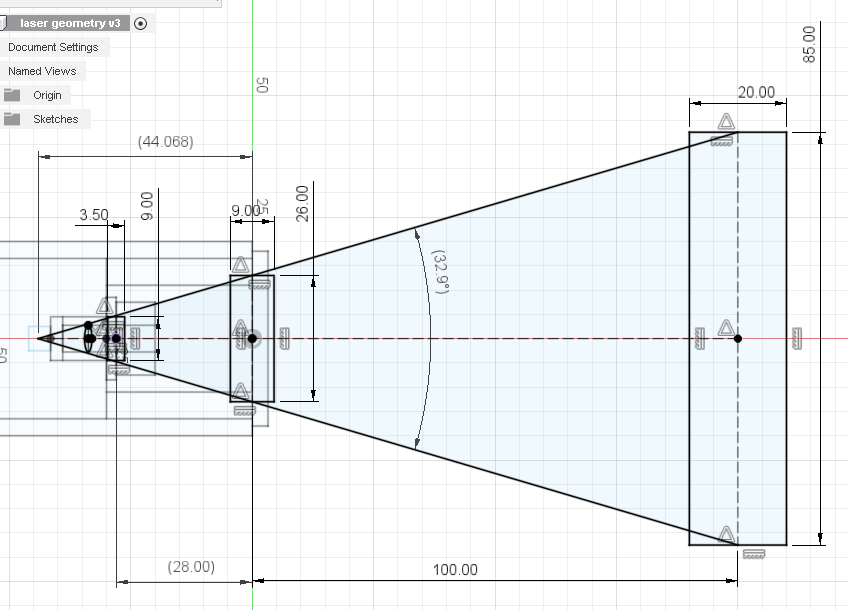
By plotting out the measurements and connecting the dots we can approximate where the origin or focus point of the diode laser is and its relationship to the lens.
![]()
One thing to notice right away is how fast the fast axis spreads out. The lens we are using has an aperture of only 5.5 mm with the retention ring in place. That limits how far away from the laser you can move the lens before the housing starts to seriously block the edges of the light. Here is an example with the lens screwed out about half way in the housing. Notice that we are blocking about 1/3 of the laser light!
![]()
Given the above information and by experimentation we can work out the practical limits on our focus range. With the lens screwed all the way into the housing we get a focal distance of about 40 mm from the base of the laser. And with is screwed out 2 mm from the housing we get a focal distance of 0 mm from the base of the housing (as close as physically possible).
![]()
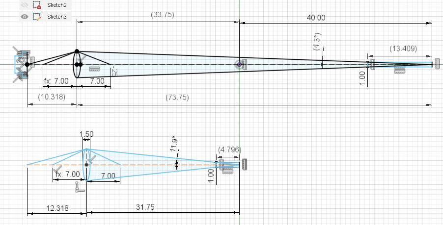
Putting it all together we can work out the geometry of the lens, focus point, and laser. Using the thin lens formula from the articles linked above we can plug in the above values to double check them. The thin lens formula is:
Where s is the distance from the laser to the lens, s" is the distance from the lens to the focus point, and f is the focal distance of the lens (7mm). Doing a bit of algebra we can solve for any variable. In this case lets solve for f and see if we were close on our lens focal length. A little algebra gives us:
Plugging in 10.318 and 73.75 for s and s" we get an f value of 9.1 mm, and plugging in 12.318 and 31.75 in for s and s" we get an f value of 8.9 mm. I think that I must have measured the lens incorrectly and it is in fact a 9 mm focal length lens, although it is possible some other part of the measurement was wrong.
Anyway this does not solve the problem of knowing what focal length is better but it does get us a bit closer to understanding how the laser works.
You can see in the last image that a longer focal length does make for a more narrow beam, and that should translate into better performance when cutting material. I marked out the depth each would cut if they removed 1mm of material, you can see a large increase in depth with the 40 mm focus height (from the bottom of the housing). I will try to setup a test to verify this one way or the other.
-
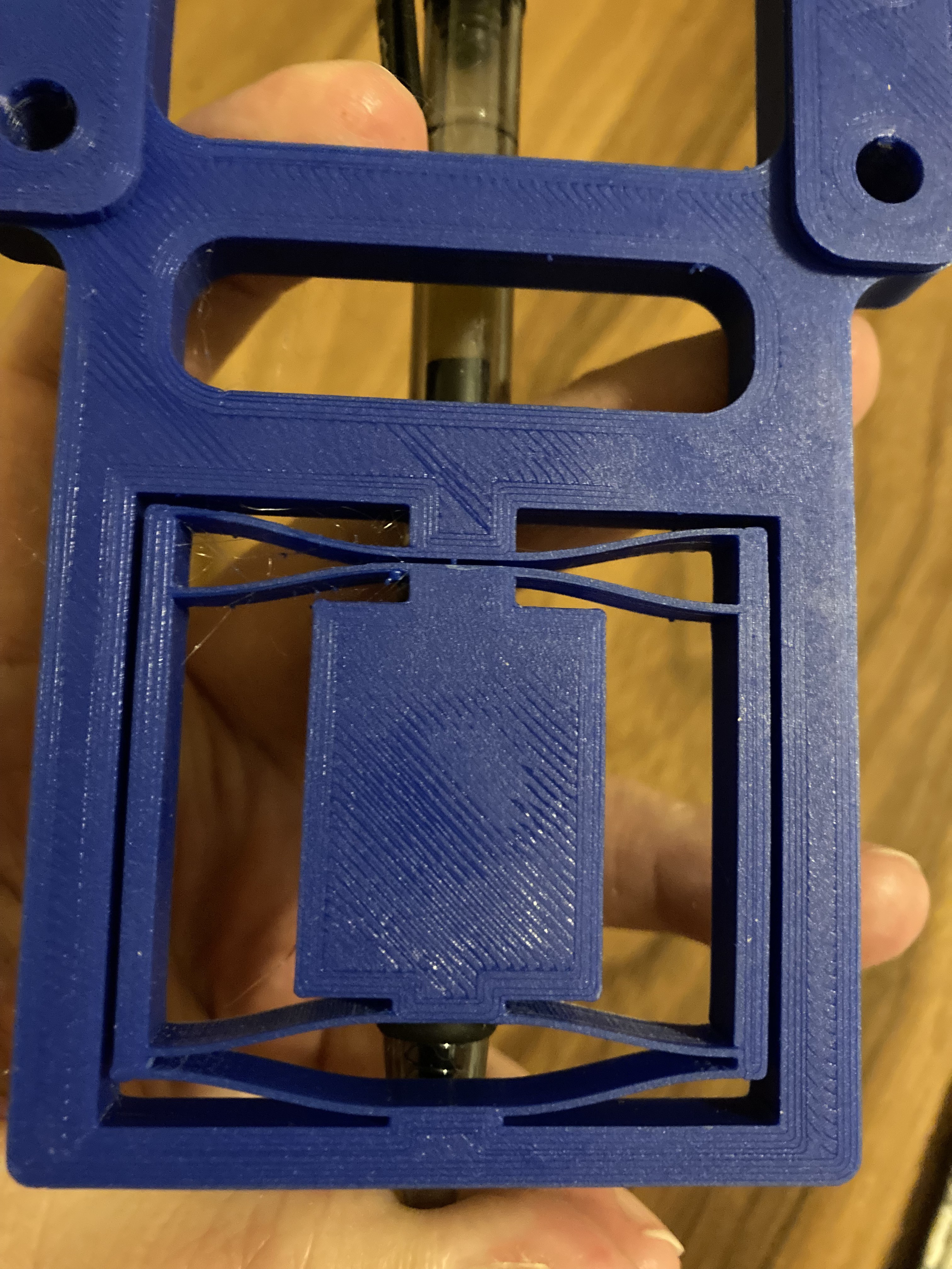
Flexures
06/21/2021 at 04:30 • 0 commentsI did a small writeup on flexures, a fascinating way to make constrained motion using a 3D printer and no moving parts (nothing pivots or slides). Maybe not the most elegant writeup, but hopefully it will inspire someone.
![]()
-
Slice it up
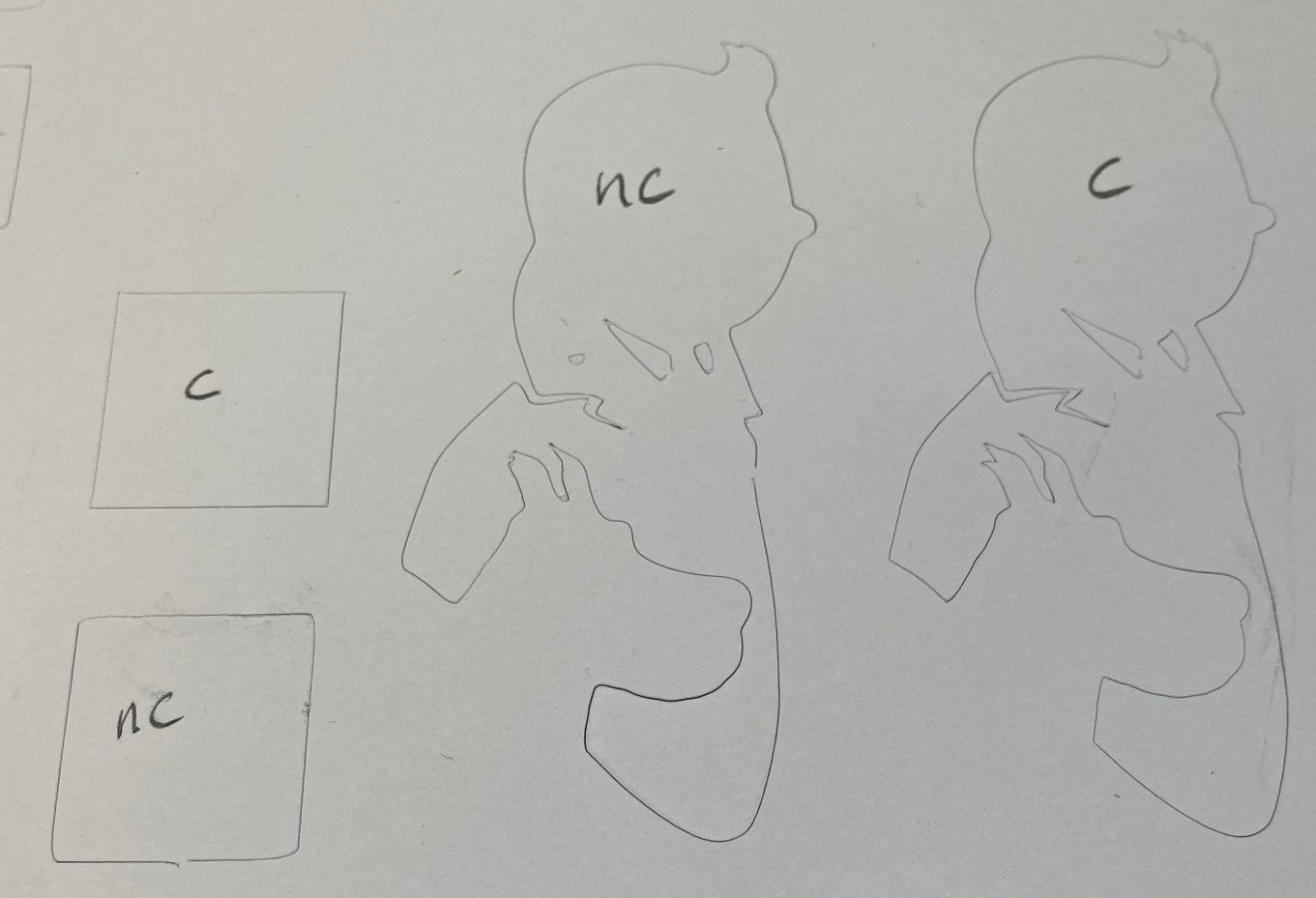
06/17/2021 at 03:44 • 0 commentsI got a chance to test out my new drag knife holder and it works great! I was worried it would still wiggle around a bit so I lowered it onto the bed with the blade retracted and ran it around for a while and it looked great. I still think you want to be careful not to lower it too much to reduce friction.
![]()
I ran two tests, one a 20 mm square and then a 70 mm tall Tin-Tin and Snowy. I ran each twice, once with the raw gcode from Fusion 360 (marked NC above) and again with the correction using the DragKnife plugin for Fusion360. I had previously experimented with different values and settled on a blade offset of 0.6mm and a swivel height of 0.2mm and the default tolerance of 20 degrees. These seem to work ok, although I think the blade offset is set too high, I may try 0.5mm next time.
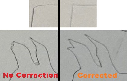
![]()
You can see from the pictures above that without correction the corners are soft and sharp turns tend to be lost. The correction seems to have helped a lot. I'm not sure that this blade needs any lift at all to work, it is so small and the cardstock paper is so thin (0.3mm) that it did not seem to do much at all. I need to experiment with setting the lift height to 0 to see if we can save time on the corners by avoiding the lift motion.
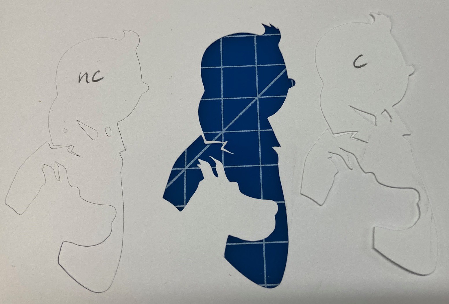
I just taped the corners of the paper to my waste board and I ended up having trouble with the paper moving a bit. I had to hold the paper down during the cut to keep it all stable. I really need to look into how to apply a sticky substance to my cutting mat that will hold the paper still without holding it too well. You can buy special matts with sticky applied that are made for cricut style cutters from Amazon as well.
![]()
The details are amazing, it looks as good as with the laser cutter, or at least close enough. That brings us to the question of what is better, a laser or a drag knife. The answer is (as always) it depends.
Drag knife pro's:
- Clean, safe and quiet. You can run this indoors without any worry and without needing to watch it while it runs. If the material comes loose the job is lost but there is zero danger of fire or serious damage.
- Kid friendly(er). Nothing about this machine is really kid friendly, there are too many exposed parts, however a cricut or other personal drag knife machine would be quite safe, with only a small chance of nicking your finger if you got ahold of the blade.
- You can cut materials like vinyl stickers without worry of dangerous chlorine fumes.
- You can cut foam, cork, thin clear plastics and coated paper that lasers won't penetrate.
- Can cut really fast on certain materials, I used a cutting federate of 2000 mm/min, although I doubt we ever got close to those speeds with these small cuts.
- You can cut partially through the material by controlling the blade height (how far out of the holder it sticks out) .
Laser pro's:
- You can cut harder and thicker materials like plywood that the drag knife won't penetrate.
- You can etch certain materials like metal and glass (with the right laser and accelerant).
- Can burn the surface of certain materials such as wood and some plastics to draw as well as cut.
- It never touches the material so there is less chance of tearing on thin details.
- Material setup is simpler, no need for a sticky backing. However dealing with fumes probably counters this benefit.
- More tolerant of any warp in the material or waste board. Keep in mind that neither are very tolerant, but the drag knife blade sticks out less than 0.5 mm so you need a very flat working surface. While a laser can probably handle several mm of deviation without too much trouble.
- Can more easily cut perforations.
- Better accuracy, the drag knife can still fail if you are not careful to start each cut in the same direction as the previous cut ended.
- Lasers Baby!
I'm not sorry to have both, I'm sure I will use each. For now I'm more attracted to the laser but the drag knife really is the better place to start. I have the parts to try and make a larger drag knife based on a utility blade. This would allow me to cut thicker material like cardboard and cork. I'm working on a 3D printed holder that is strong enough for the job but that only uses a few bolts and some skateboard bearings.
MultiBot CNC v2
A low cost 3D printed CNC that can be built with minimal tools yet is capable of great things.