I decided to run a few more tests now that I'm all setup to measure cut depth. I ran all of these on the pine since the MDF does not seem to cut quite as nicely. I ran using my NEJE 30w laser at 80% power and 150 mm/min speed. This was using the Simple Deluxe 1189 aquarium pump as an air source.
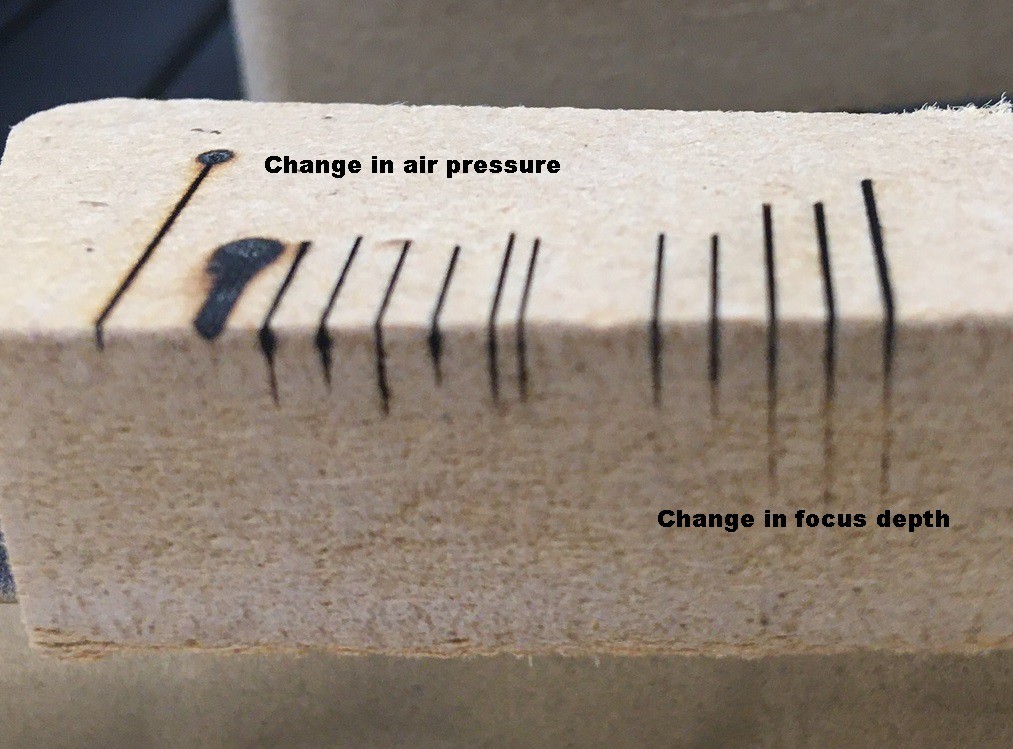
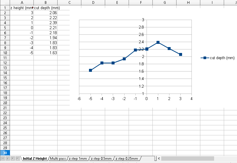
For the first test I cut a series of lines all using a single pass but varying the focus height from 3mm above the surface to -5 mm below the surface. You can see from this that I probably have my focus set wrong, it appears that being 6 mm above the surface is more in focus than the 5mm I'm currently using. It is also possible my focus block is not made correctly, I need to double check it.
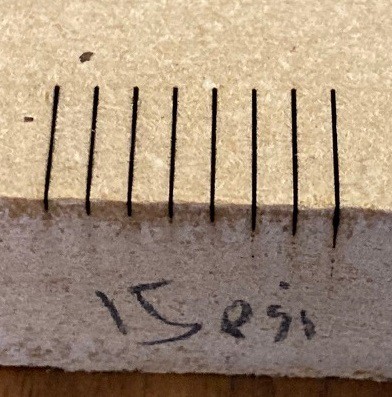
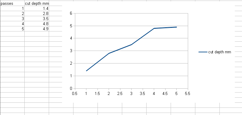
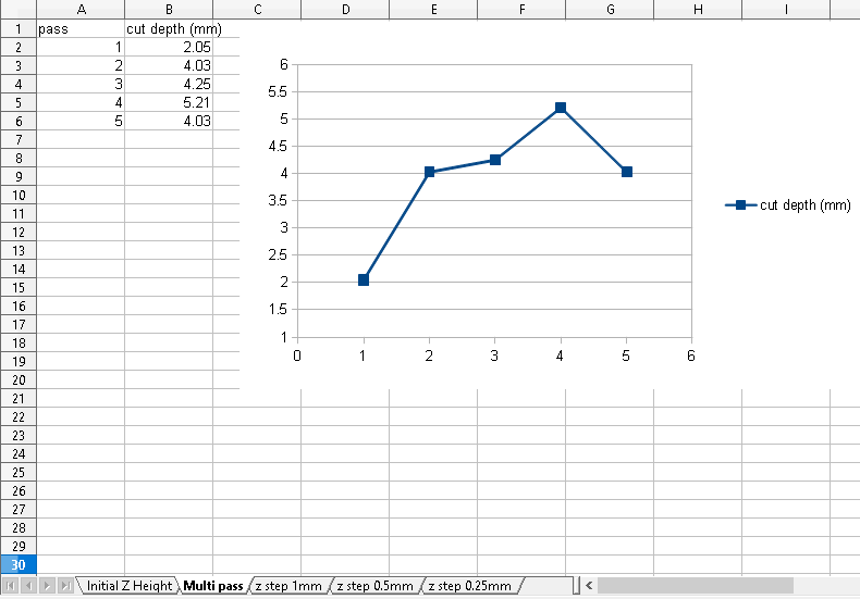
For the second test I focused at the surface, but ran 1 to 5 times over the same line without lowering z. Running twice over the same line seems to have a nice improvement in cut depth, from there it is a bit inconsistent. The 5 pass cut is actually worse. I suspect I'm getting charred material caught in the cut and that is messing up the measurement.
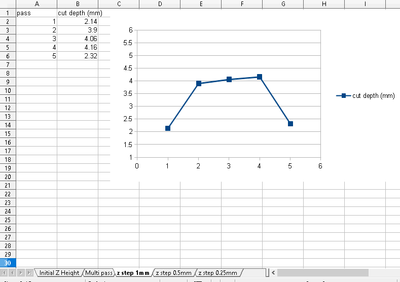
Finally I repeated the same experiment but lowered the laser on each pass. This is the data where I lowered the laser by 1 mm each time. You can see the same behavior as the last one, there is no significant benefit. For some reason the 5th pass is making things even worse, still can't explain that.
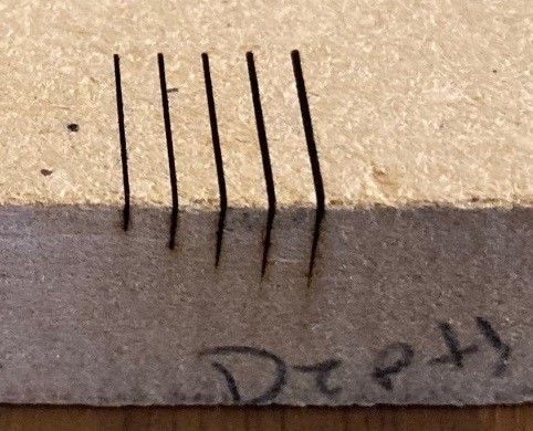
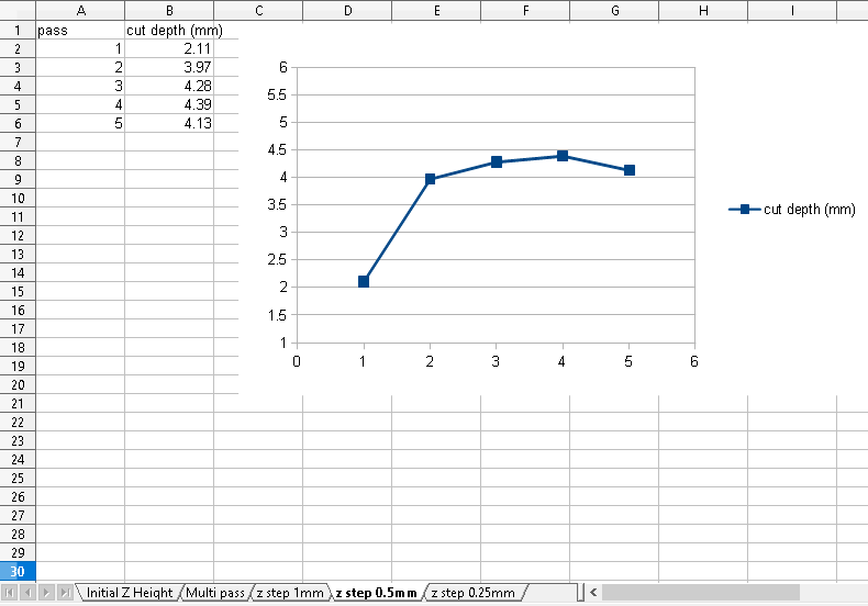
Same as above but lowering by 0.5 mm on each pass, this fixed our last pass issue, but otherwise shows no significant benefits.
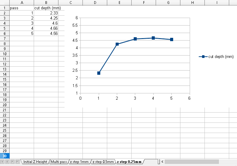
Finally lowering z by 0.25 mm. I suspect my measurements are drifting a bit since my start depth is magically deeper when using identical parameters. Anyway we are seeing a small benefit to this, at least it is more consistent.
In summary multiple passes help a bit but lowering the z on each pass does not seem to have a significant benefit on pine at least. It is interesting that there is an upper bound on the cut depth. I suspect lowering the laser makes the beam hit the side of the walls more causing a loss in power at the bottom of the cut.
---
I did another test, running 19 times over the same line and lowering the cut by 0.25 mm on each pass, just to make sure the above data is not just a hiccup of some sort. I rand it twice, once at 150 mm/min and again at 50 mm/min (3x slower). I measured the cuts at 6.94 mm and 7.05 mm, those are within the noise on my measurement. Basically lowering the laser speed has no benefit in this case. It could be that this is the limit of how deep we could cut with this laser on pine. For sure this laser can't cut super thick materials, we probably need to stick with 5 mm ply or thinner.
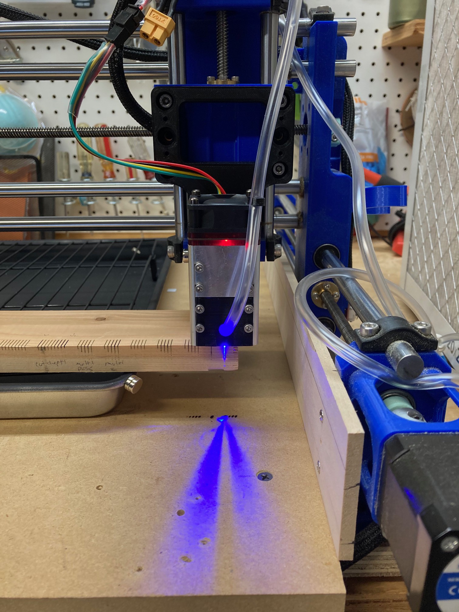
One thing I noticed when running this, my target was hanging off the edge of my pan and so the laser would come into contact with the waste board on every cut. That resulted in a series of burns in the waste board. You can't quite see it in this photo but the defocused laser spot was about half an inch wide and it still burned the wood easily. It is giving me newfound respect for the laser, I can see why reflected light is so dangerous.
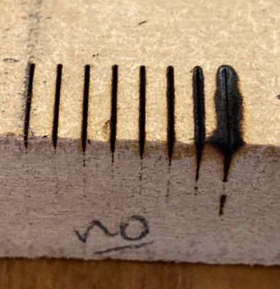
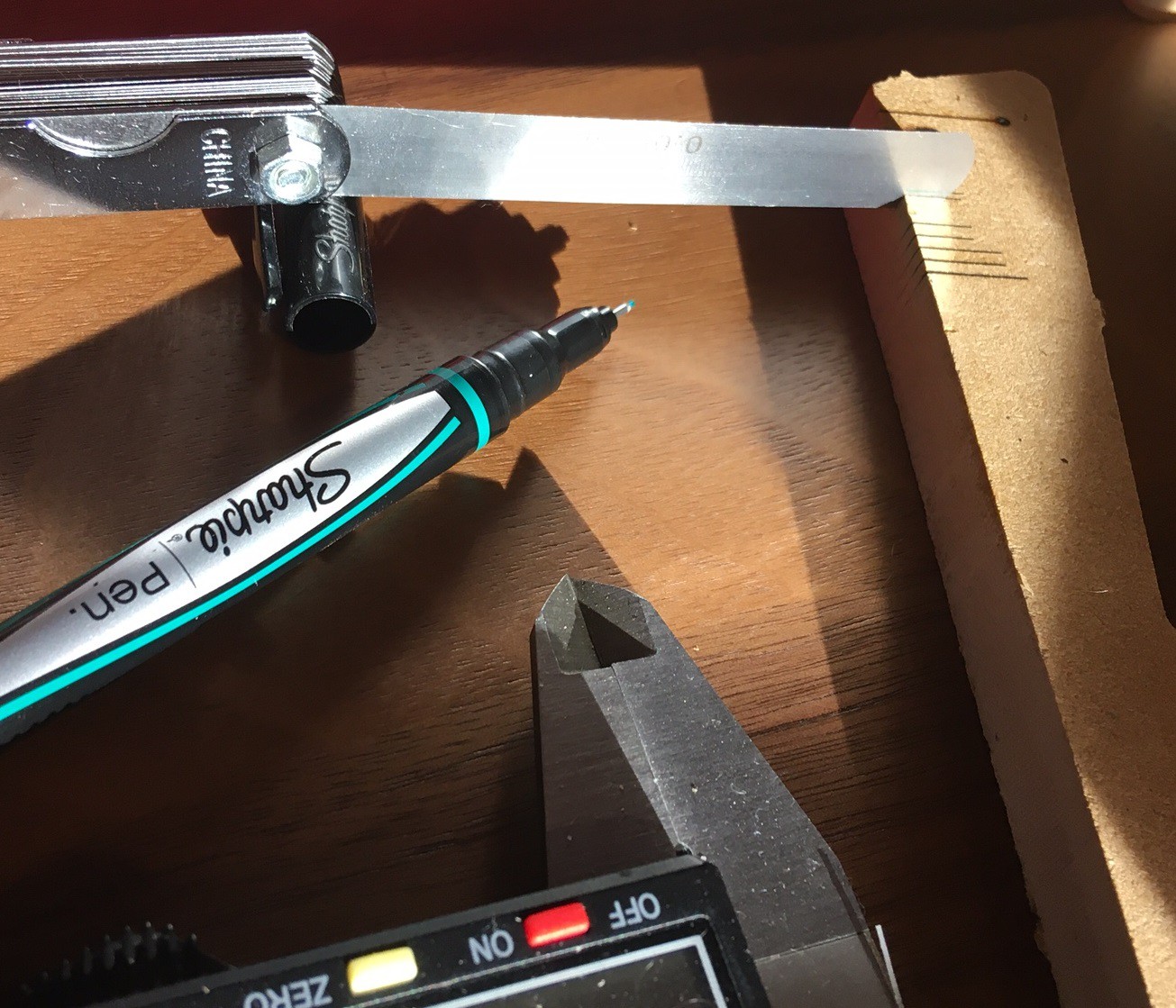
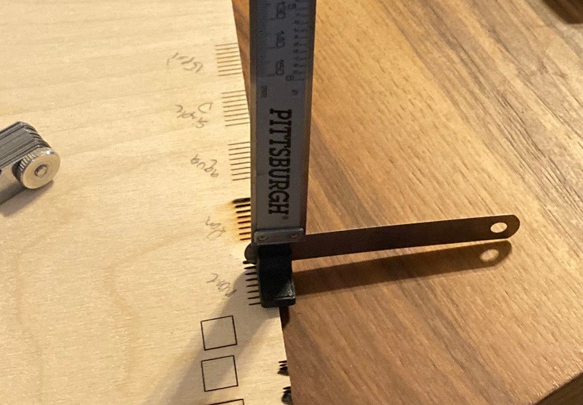
I have been struggling with finding an optimal way to measure the cut depth on my recent tests. I have tried several things but none of them were very repeatable. I finally hit on a new idea. I printed a small right angle and added a 6mm magnet to it then removed a 0.076 mm feeler gauge from my pack and used the right angle to hold it in place. Finally I used my calipers to measure the height from the top of the gauge to the tabletop, after first zeroing the whole thing out on the surface of the material. This allowed me to get a reasonably accurate measurement of the cut depth, within 0.1 mm or so at least.
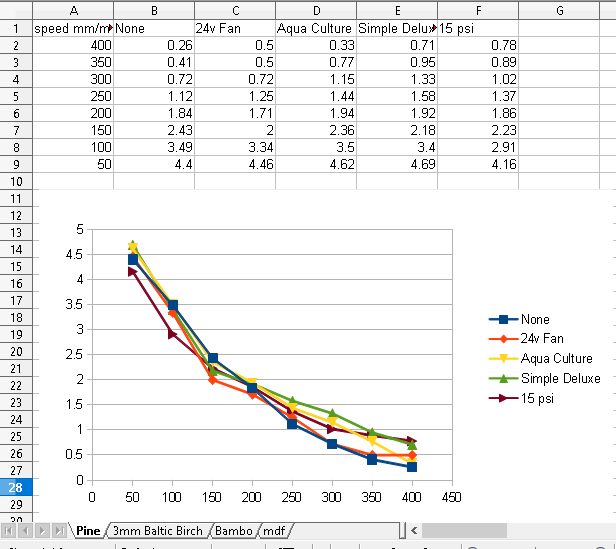
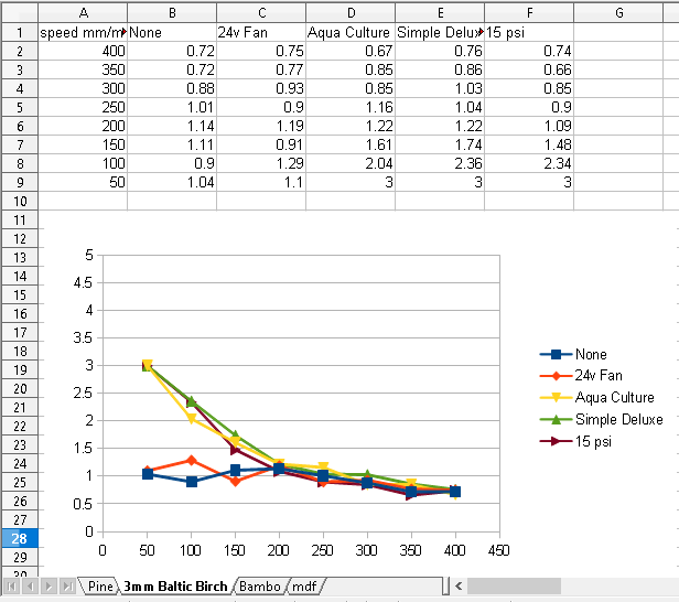
This seems to be working quite well and allowed me to measure all the cuts I made previously and summarize them in the tables below. These are all run with a NEJE 30w laser focused 5 mm below the base of the laser housing and run at speeds between 50 and 400 mm/min and using various air sources as seen in the link above.
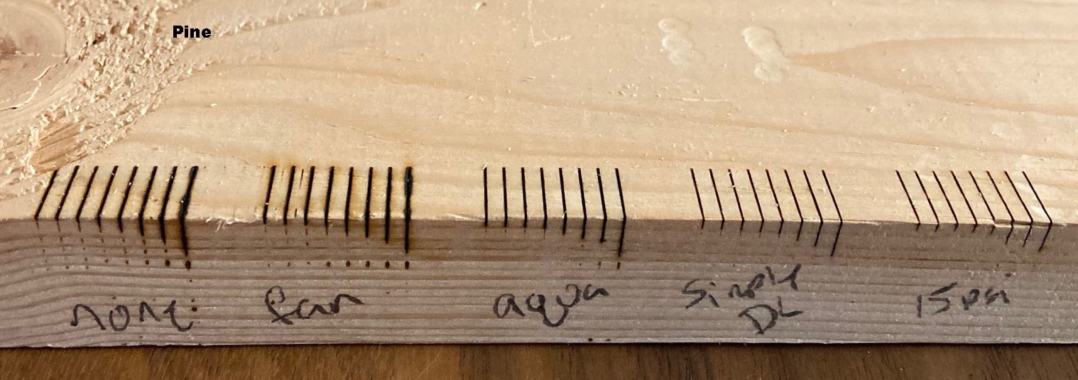
Pine works the best, we see a very nice relationship between cut speed and cut depth, the air assist has little impact on the cut depth, but does improve the look of the cut for sure. There is a 0.5 mm improvement with air vs no air, but it is nothing to write home about. Notice that cutting the speed in half results in less than a doubling in cut depth so it is possibly faster to run multiple passes at a faster speed than one pass at a slower speed. However you will need to really look closely at this, any non cut moves may push the balance in the other direction.
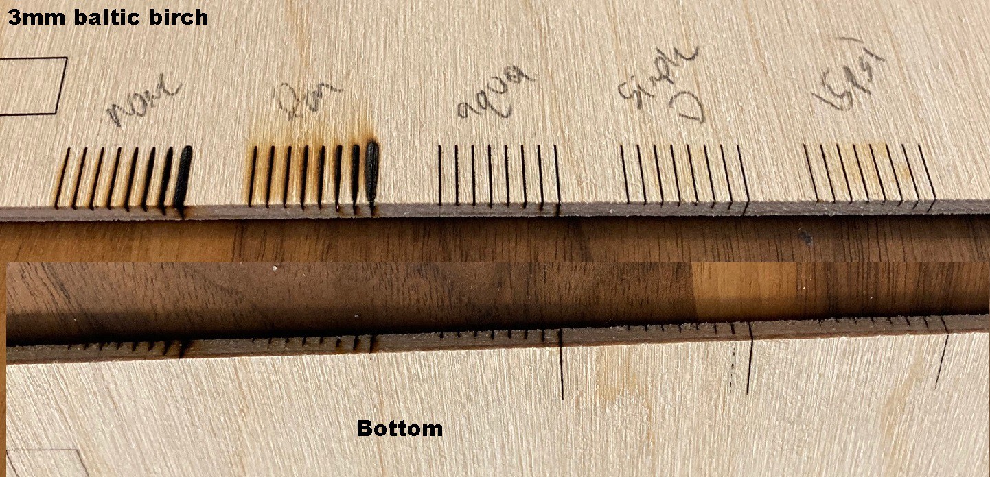
The 3mm Baltic birch shows a very clear benefit with the air assist. The fan and no air options don't increase there cut depth, no matter how slow we go. While any air focused at the cut gives us a very clear benefit. Also not using focused air causes a lot of charring on the surface.
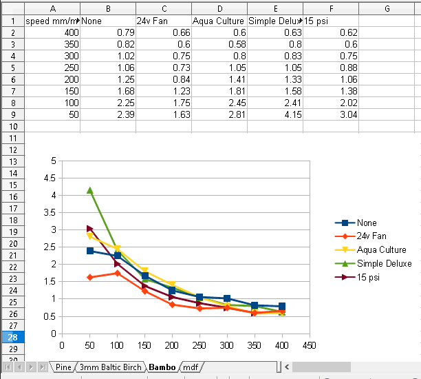
Bamboo is similar to the pine, but at the end the numbers go a bit out of control. I double checked the measurements and they are accurate. I suspect the spread is a bit random and has more to do with the non uniform nature of the material. I'm not sure how bamboo sheets are made but I would expect glue is involved, and it is also a very pulpy material.
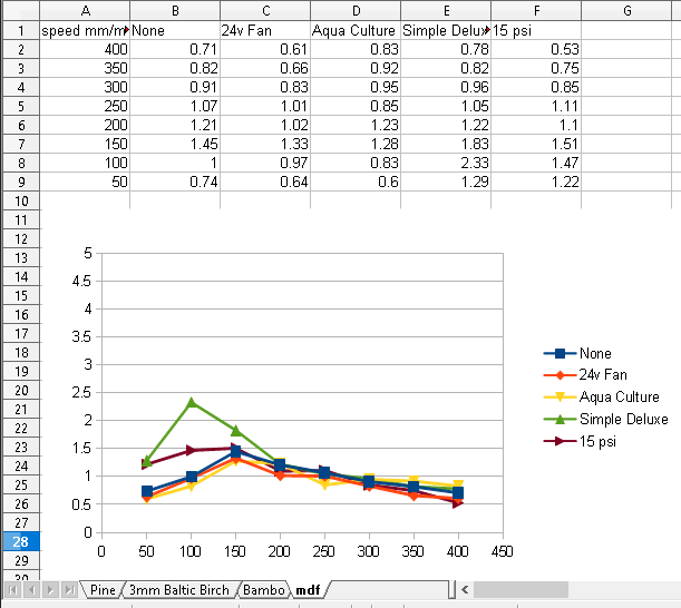
MDF is the strangest of the bunch, there is a clear loss in cutting power at speeds below 150 mm/min. Again the green simple deluxe trace looks unusual but I double checked the measurements and they are right. I suspect it is an anomaly in the material.
Anyway the loss of cutting power with slow speeds is hard to explain. Maybe the material starts burning when the speed is too slow? However there is little benefit from more air pressure. Maybe it would take a significant increase in air pressure to really benefit. This is a very gritty material, it almost feels like sand that has been glued together. It is possible that is throwing things off a bit.
---
In summary it seems clear from this data that increased air pressure does not help much in improving the cut depth. However from our previous test it does help improve the look of the cut, and visually it makes the kerf thinner as well. Basically if you have enough air then you have enough, more does not seem to do much for you. The $15 Aqua Culture 20 gallon pump is still probably a bit too small for our usage. You probably could get away with a pump double the size, but I'm afraid that will push you near to the cost of the $45 Simple Deluxe pump that has much more than double the output of air. I still feel this pump is the best compromise between cost and performance for my applications.
Keep in mind that we are dealing with about 5 watts of optical power here. Going with a 40 watt K40 laser or even better a 100 watt laser will probably require more air to help quench the flames. However I suspect the trend will hold true and once you have enough air to make the cut look good you probably won't see a large benefit from using even more pressure.
---
I need to do some speed tests between slower cutting speeds and multiple passes to see if there is any benefit at all to using a slower speed if you can't get through the material in a single pass.
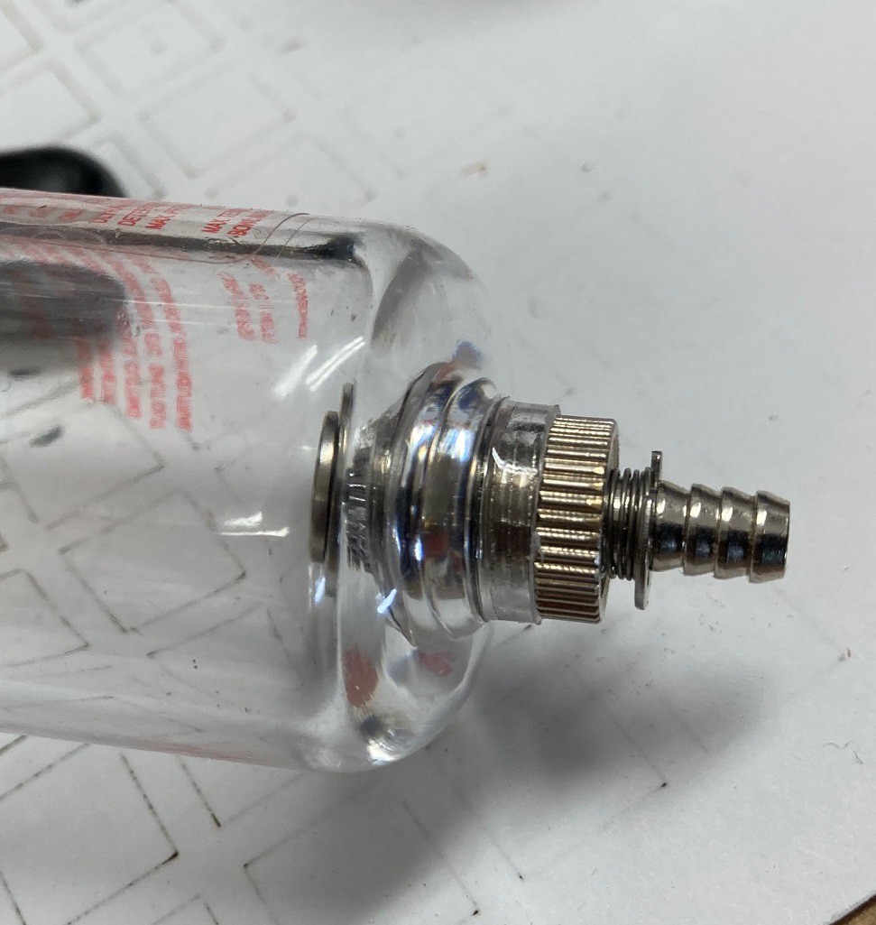
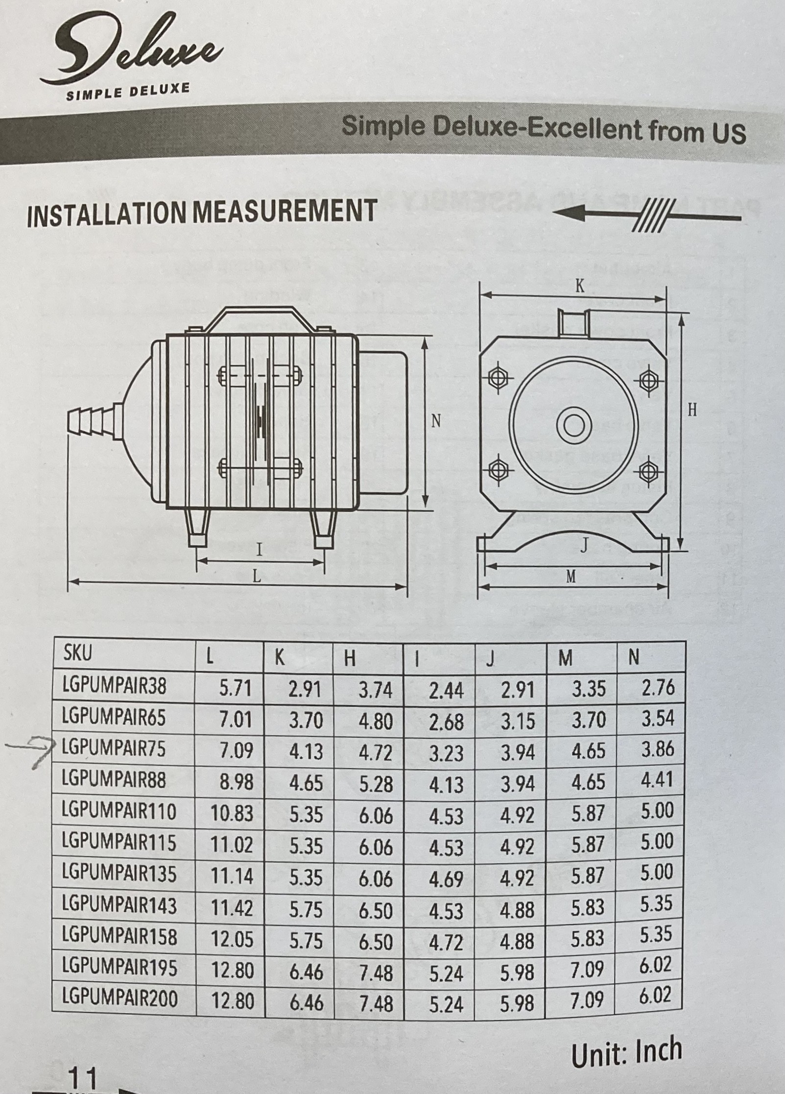
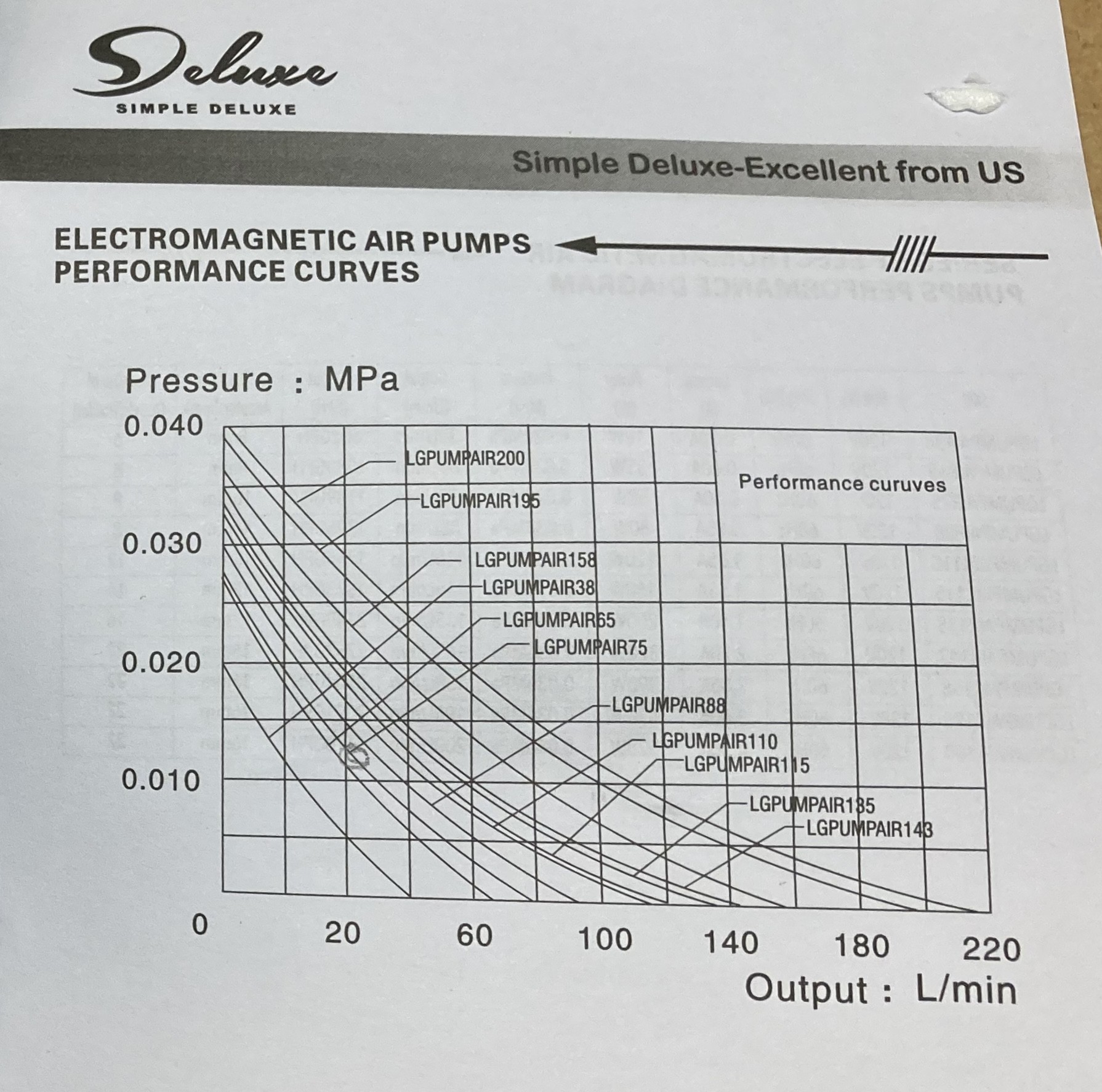
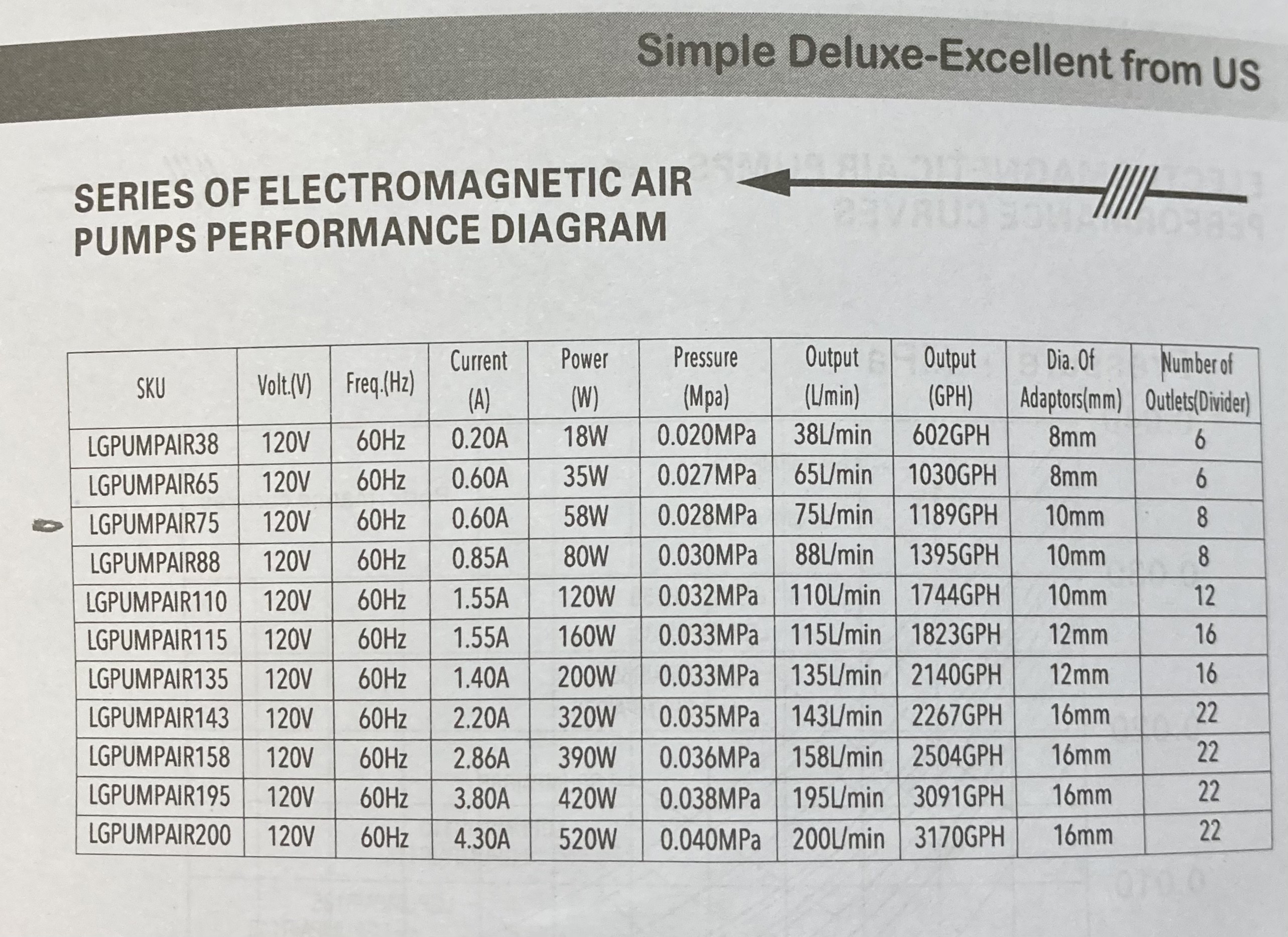
The Simple Deluxe air pump has very little technical details available online. However it came with a decent manual. Here are a few interesting pages from that.
I have been thinking for a while now that these projects updates are lost in the noise. So I decided to make a new hackaday project that summarizes my work (to some extent) so that maybe someone can find my work eventually. I don't plan on really maintaining that project, it is just a loss leader (or a desperate cry for attention).
---
I was worried my previous test on MDF was not accurate, so I ran it again with some pine, 3mm Baltic birch plywood, and a broken bamboo cutting board. The surprising news is that the $15 Aqua Culture air pump is holding its own with these materials. I suspect this has to do with them being denser and therefore less flammable. My theory is that cardboard or paper would not fare as well with this low flow pump. That is another test I need to do someday.
I also need to slow things down even more to see if we can get more depth out of the cuts. And I need to quantify the speed tradeoff between going slower and deeper vs faster with more passes. I suspect there is a sweet spot hiding in there somewhere.
—
it has worried me that previously I saw a clear correlation between air pressure and cut depth yet none of these tests seem to show that.
I think there are two parts here. The new sealed nozzle is probably more efficient so the smaller pumps work better. And previously I was measuring near the front of the cut and this time I measured near the back. I think the laser was able to burn deeper near the front where the air was able to flow more easily. There is definitely a deepening of the cut near the front at least.
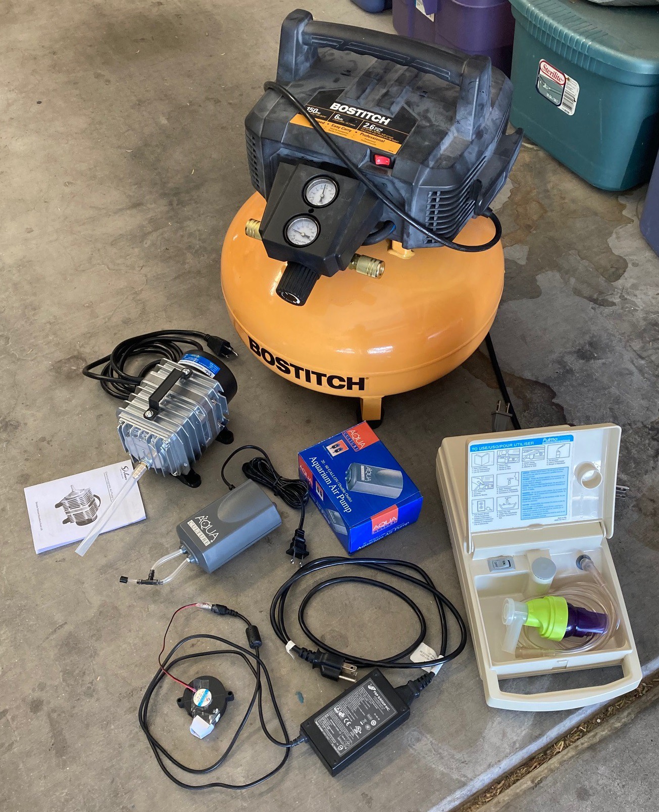
I have been on the hunt for a while now to try and work out the best way to use air assist with a laser diode. I would like to maximize the efficiency of the diode (get the deepest cut) as well as make sure the cut is as clean as possible and finally to do it all with the lowest cost and least noise. I decided to do a shootout with all the air pumps and compressors I have access too.
24v radial fan from an ender 3 to see if an air compressor is even needed ($1)
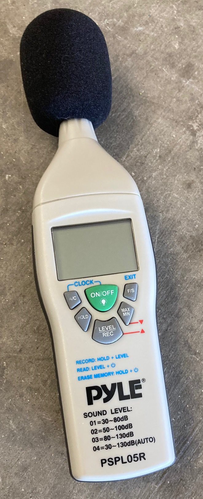
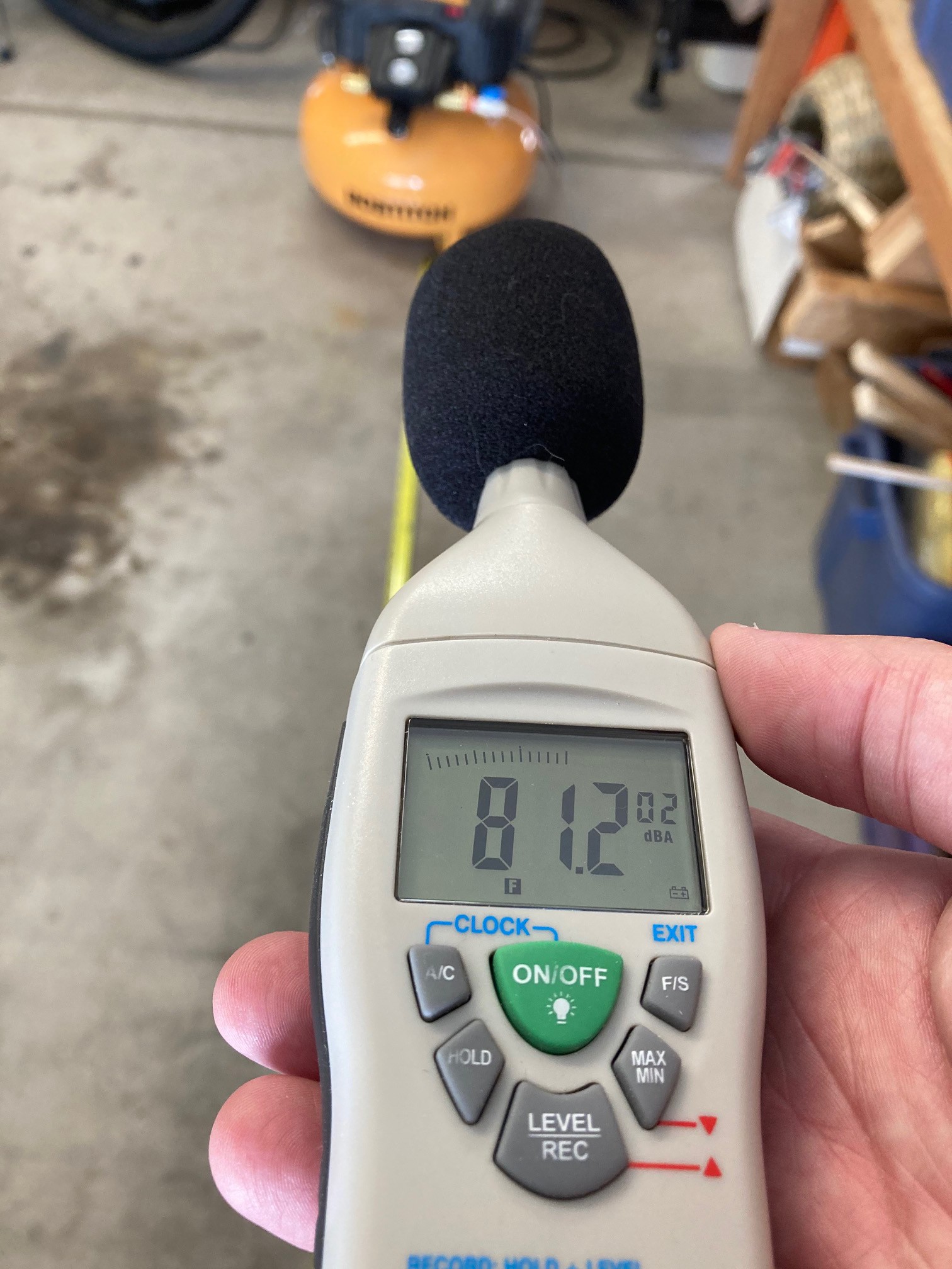
First for the noise, I just happen to have a Pyle dB meter laying about. I measured the dBA right next to each compressor as well as 5 feet away, all within my enclosed garage.
I also measured the max PSI each compressor could produce when no air flows, as well as the PSI when air is flowing unrestricted through my 2 mm nozzle. The results are summarized below.
Name
0 ft dB
5 ft dB
psi (air off)
psi (air on)
Bostitch 90 psi (15 psi regulated)
91
81
15
15
Simple Deluxe
64
52
5
3.5
Sunrise
78
68
19
3
Aqua Culture
46
35
3
?
24v fan
54
42
?
?
The ambient noise in the room was hovering between 30-50 dB, any measurements below 50 dB are probably not very accurate and can be considered basically inaudible.
The Sunrise compressor is capable of producing a surprising amount of pressure, but once you let the air flow the pressure falls dramatically. That plays out below with it not working as nicely as the simple deluxe air pump. The big news is that the simple deluxe manages to be significantly quieter than the Bostitch. It can't compete on the pressure level but if it can get the job done it will be great.
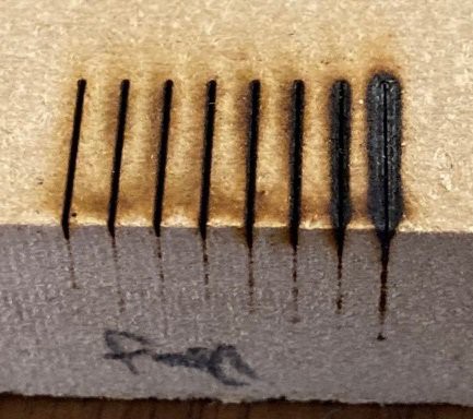
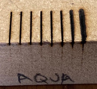
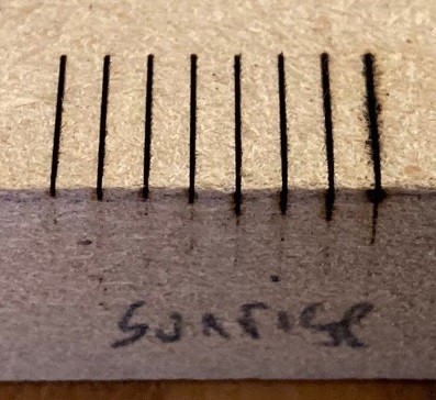
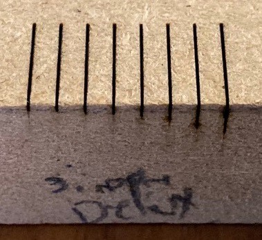
The next step was to evaluate how each works when pushing air through my over the lens nozzle with a 2mm orifice (or blowing at the side in the case of the fan). To test this I wrote a program to draw a series of lines, focused at the top of the work piece at 80% power and at speeds from 400 mm/min to 50 mm/min in steps of 50. The test pieces are shown below.
No air assist24v radial fanAqua Culture 20-60 gallon aquarium pumpSunrise nebulizer pumpSimple Direct aquarium pumpBostitch at 15 psi
Looking at these results, the radial fan is worse than no air assist. It blows the smoke back onto the workpiece and just makes a mess. No air is not very good, even a fast cut has a lot of extra scorch damage. The Aqua Culture pump is where we start to really see the value of air, it is more than enough to improve the lines as long as the laser is moving fast enough that we don't start a fire. However at slower cutting speeds (deeper cutting depth) we still see a lot of scorching. The great news is visually the simple direct pump is almost as good as the compressor at 15 psi. We know from previous tests that the compressor at 30 psi cuts even better, so the compressor is always the winner but a $45 aquarium pump is both dramatically quieter and still good enough for most work.
I tried my usual trick of using feeler gauges to measure the depth of the cut. However for some reason I am not seeing a significant change between the cuts. There is a large jump in depth with power, but going form no air to 15 psi only saw a 0.2 mm increase in cut depth. Part of the problem may be that I used a larger 0.1 mm thick feeler gauge rather than the 0.02 mm thick gauge I used last time. The 0.02mm gauge is paper thin and I was worried about damaging it. Cutting the speed in half did roughly double the cut depth.
I wrote one more test program that runs the laser at 150 mm/,min, 80% power, with 15 psi of air and that takes 1 to 5 passes across the material, lowering the laser by 1 mm on each subsequent pass. This proved to be very effective, with each pass deepening the cut by approximately 1 mm. Things seemed to flatten out on the 5th pass, it is not clear if that is just the end of what the laser can do or if the bottom of the cut was just deep enough that we would need a 6th pass to bring the laser back into focus on the bottom of the cut.
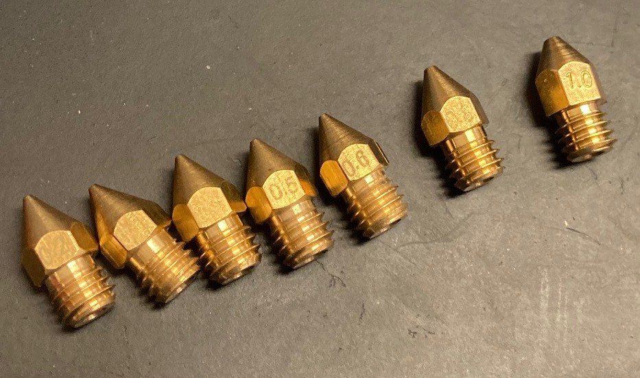
I recently remembered that I had picked up a variety pack of cheap nozzles for a 3D printer a long while ago. The quality was so low I did not end up using them, but they do have holes that range from 0.2 mm to 1.0 mm in size and so I could compare them to my 3D printed nozzles.
I'll keep this short, they did not work. I tested them on every compressor I have access to and in every case they were less effective than my 2 mm test nozzle. The air flow was lower, and the velocity at the tip was also lower. I think there is so much friction at the outlet that they constricted the air flow beyond what Bernoulli suggests. However the 1.0 mm nozzle was not too far below from my 2.0 mm nozzle, and my 2.0 mm nozzle was a solid improvement over the 5 mm tube with no nozzle. This just reinforces what I found earlier with my test nozzles, there is some sort of an optimal nozzle size near 2 mm that maximizes air velocity at the tip.
I suspect we could measure CFM for various nozzle diameters and would find that there is a non linear relationship where CFM falls off rapidly below a particular nozzle diameter. I will save that experiment for another day. I did find that the 1.0 mm nozzle produces a more steady flow than the 2.0 mm nozzle when using one of my smaller air pumps. However I don't think a smooth flow of air is nearly as important as a strong flow of air.
In doing all this testing I noticed that the water separator on my regulator leaks at very low inlet pressures. It needs 10 or so psi for the auto drain valve at the bottom to fully engage. Since we don't have any humidity in the air I never end up collecting any water anyway, so I took the valve apart and moved the spring from the top to the bottom so it holds the valve closed by default and you now have to manually push up on the valve to drain. This seems to work well and allows me to hook my low pressure air pumps to the inlet side without causing an air leak.
Since my operating range for air pressure is between 5-30 psi for cutting the 160 psi gauge on my air regulator was not very accurate. So I decided to pick up a Winters 0-60 psi 1/8" NTP gauge to replace it with. This is working great, the gauge starts to register at 3 psi, and appears to be quite accurate. It is much easier to dial in an exact value. I don't know that I need this level of control, but it is miles ahead of the mess on my compressor and will let me test more precisely going forward.
Bernoulli's equation can help us understand a bit more about what is going on between pressure and velocity with our compressor. In its simplest form (ignoring the gravity term) it is:
Where P is fluid pressure, ρ is fluid density, and v is fluid velocity. Assuming the density is a constant then this can be simplified into approximately:
This basically says that cutting the pressure in half gives us a 4x increase in velocity. You would think we would need an increase in pressure to get an increase in velocity but that is thinking about it backwards. We are releasing the pressure, it is at some psi in the line but when it exits the line then pressure drops to 1 psi or standard pressure. If there was no drop in pressure then there would be no velocity (no air would move).
I'm not exactly sure how this relates back to CFM, I guess cfm is just velocity over time.
Anyway the idea is that a doubling of supply line pressure results in a 4x increase of velocity at the outlet. Since area of a circle basically grows with the square of diameter then a halving of the diameter also results in a doubling of the exit velocity. Of course this is all in an ideal environment, there is a limit to how much we can increase the line pressure or reduce the nozzle diameter. There are line losses and turbulence at the nozzle that will sap energy.
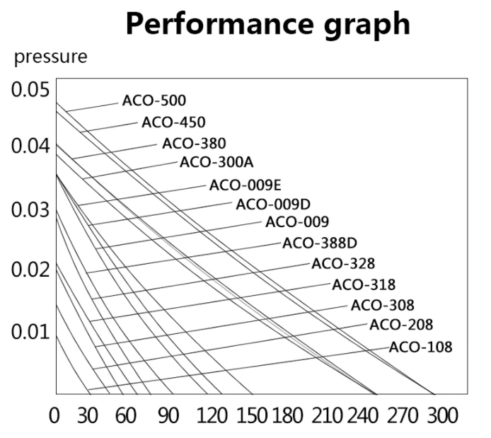
Not quite related but here is an interesting graph I found that compares line pressure to flow rates (liters per hour I think) for several of those metal aquarium air pumps you can get from AlliExpress and Amazon. You can see that increasing the line pressure results in a reduction of flow in the compressor. This does not follow Bernoulli's principle because the air does not flow cleanly through the pump. Turbulence through the pump causes things to behave differently and that in turn gives us more of a linear relationship rather than an exponential one.
I'm frustrated with the current state of standards in America. Not political standards but weights and measurements. There is a good reason we have standards, they help the consumer make better choices and reduce fraud. However it seems more and more businesses are hiding or even obfuscating there product specifications on purpose to confuse the consumer.
Most of the tests I have been doing for the last few weeks could have been set aside if the air pumps had published specs, especially specs that followed some semblance of a testing standard. I found pumps that were rated by tank size (20-40 gallon, whatever that is), wattage, liters per hour, cubic foot per minute, gallons per hour (gallons of air?), and a wide range of pressure values as well. If I could have looked at all the pumps and seen there cfm without pressure and cfm at 80% of max pressure I could have much more easily picked one for my machine.
The same goes for everything else. Men's pants for example are measured in inches for the waist and length, but lack any real info beyond that. Women's pants for some reason have 25" subtracted from there waist, and typically don't list the leg length at all, you get 'short' or 'long' instead. Kids pants have there own measurements that further confuse everything. To make it all worse a lot of close drop sizes all together and just go with small/medium/large. Finally some clothing stores take a few inches off there size to make you feel better. The end result is you can't reliably buy clothes online because the size may be all over the place depending on where you get them from. Europe seems to have this sorted with much more standardized measurements on there clothes.
This goes on and on, mattresses have different model numbers at different stores so you can't compare them together. Air filters may have a MERV rating, or may have there own made up value like Home Depots FPR rating. Some consumer air purifier filters have there own made up ratings as well (HRF for Honeywell). I have even seen filters that have a 'HEPA like' rating. What is hepa like anyway? Again just listing the flow rate in CFM and the filter MERV rating would be enough to easily compare units against each other and to help judge what size would fit best for your use.
In my day job I do audio programming, among other things. Audio equipment is the worst. Go line up several speakers from your favorite pc peripheral manufacturer and you will see that they use different ratings between there own products so you can't compare them to each other. The shenanigan's in audio land know no bounds.
I don't blame the businesses who fail to add proper ratings to there devices. It is hard to do the right thing when someone else does the wrong. But that is what standardizing bodies and governments are for, to encourage or even demand at times that businesses act in a way that benefits the customer more than there bottom line. We need standards and need companies to follow them, it seems mundane but it is an important part of helping consumers make informed decisions and that in turn encourages good innovations rather than smoke and mirrors to confuse and trick consumers.
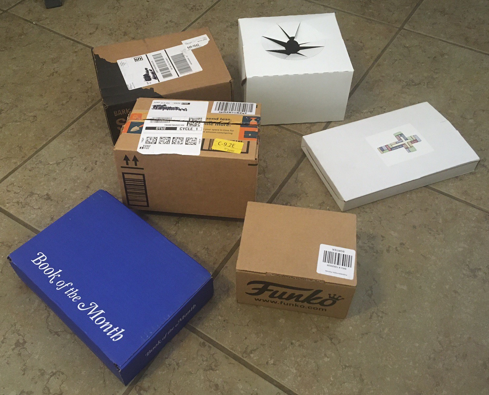
I have been hording boxes for a while now with the idea of taking them apart to work out how they are made. Well today is the day I finally send them on to the recycling bin. I have always found that one of the best ways to learn is to look at how professional products are made. Sometimes there goals are different than yours but for sure they have spent much more time thinking about how to manufacturer a product. Anyway in the spirit of learning from others here are the boxes I collected. As I get time I'm going to try to sketch each up and add it to the list.
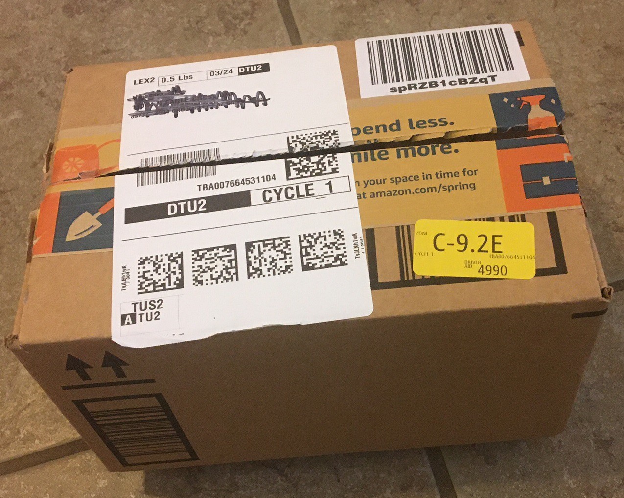
Amazon box
This is a standard box that is 23 cm x 15.5 cm x 13.5 cm and made from 1.8 mm corrugated cardboard. It has one glued edge and the top and bottom is taped together. Notice that they have left a gap of a little more than 2x the thickness of the material between the flaps. That both stops the flaps from hitting each other when the box is closed and it makes the tolerances on assembly much looser.
Cross box
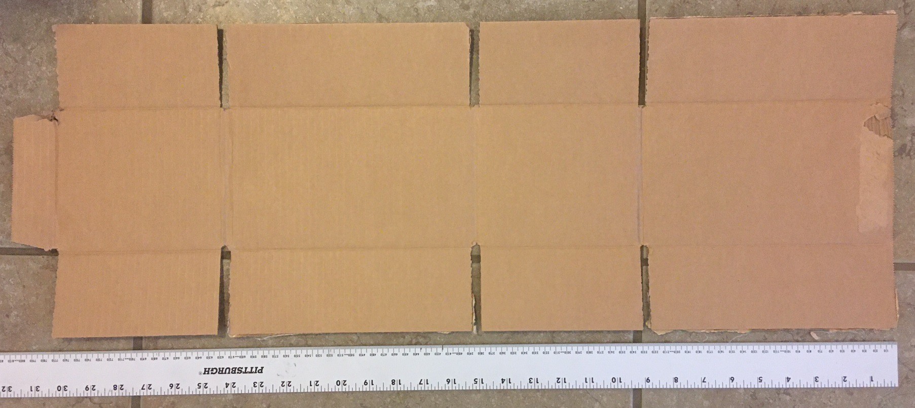
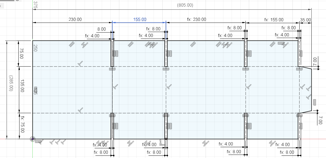
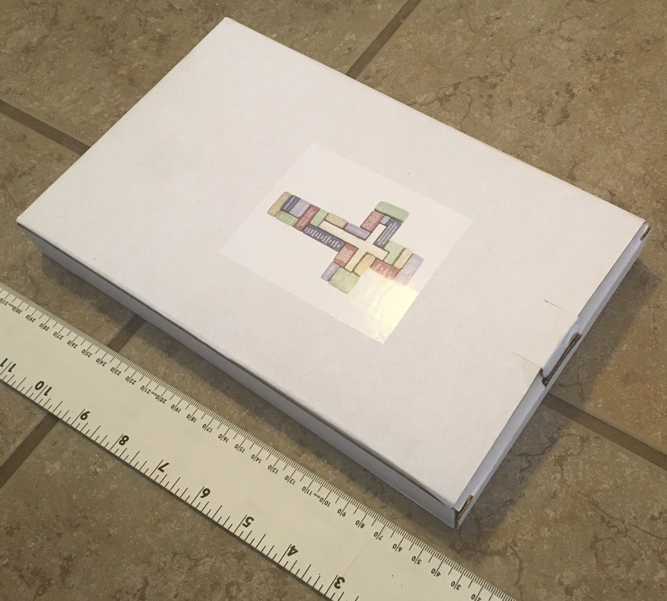
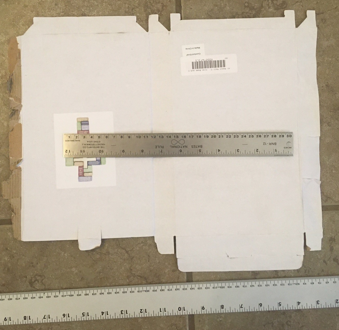
This box is 27.5 cm x 17 cm x 3 cm and is made from a very cheap 1.75 mm corrugated cardboard that pulls apart easily. It is similar to the Amazon box with one glued edge, but it uses a unique flap for the bottom that tucks together without glue while remaining relatively strong. The top has a flap that tucks in place as well but it is designed to be easily opened.
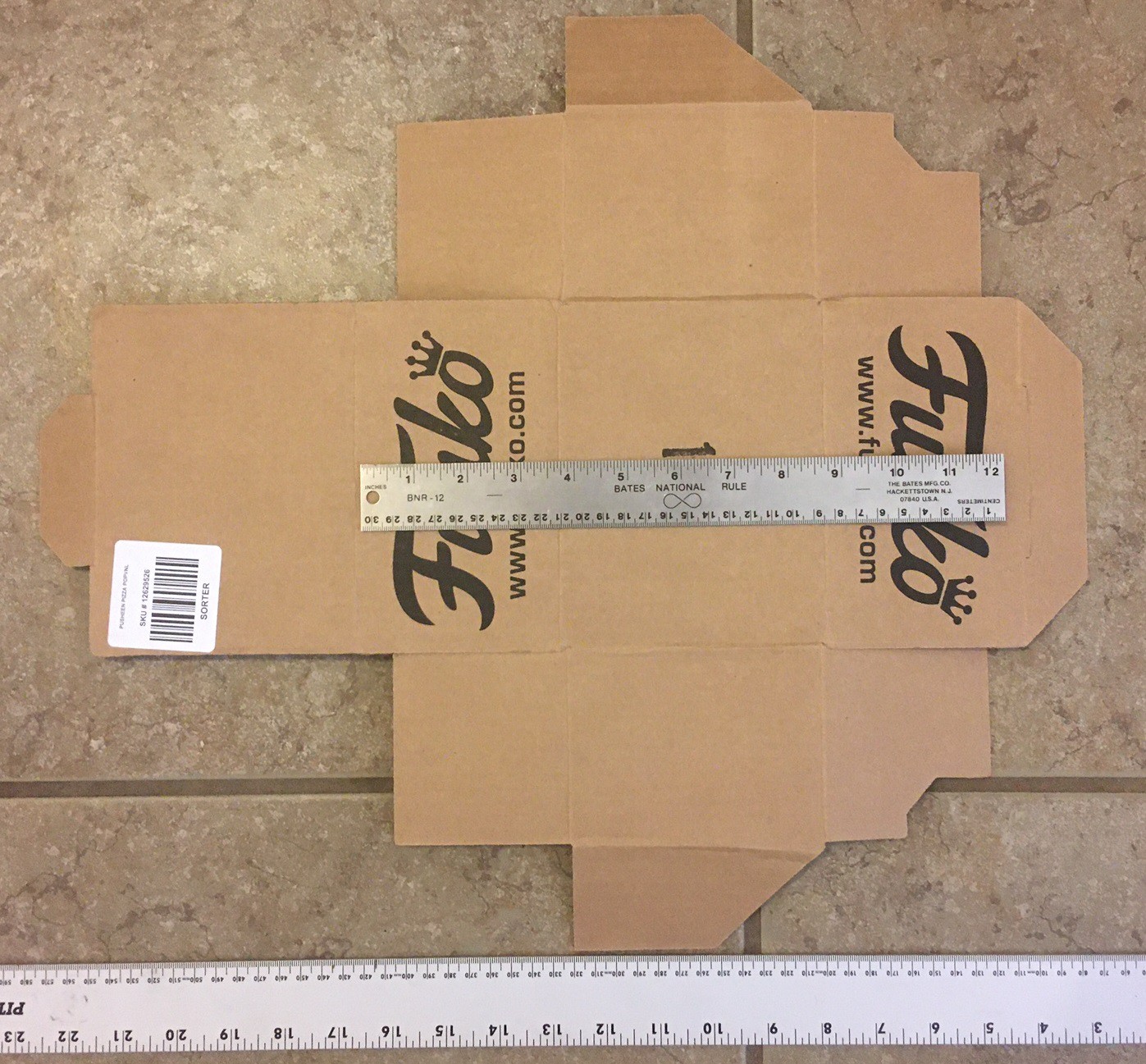
Funko box
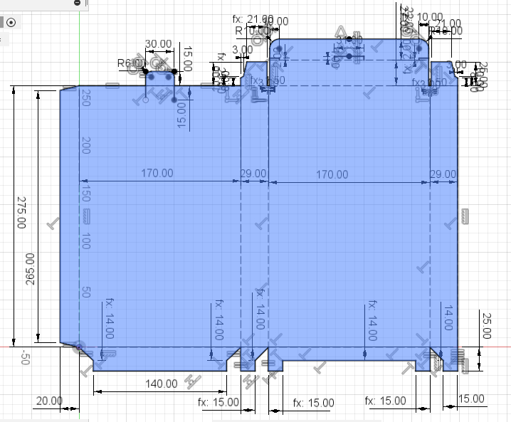
This box assembles without glue while being almost as efficient on material as the Amazon box. It is not as sturdy, in particular once the lid is released it basically falls apart, but it is functional. It has an outer dimension of 17 cm x 13 cm x 9.5 cm and is made from 2.2 mm corrugated cardboard. Notice that the sides are shorter than the back, by just enough for the bottom and top tabs to fit.
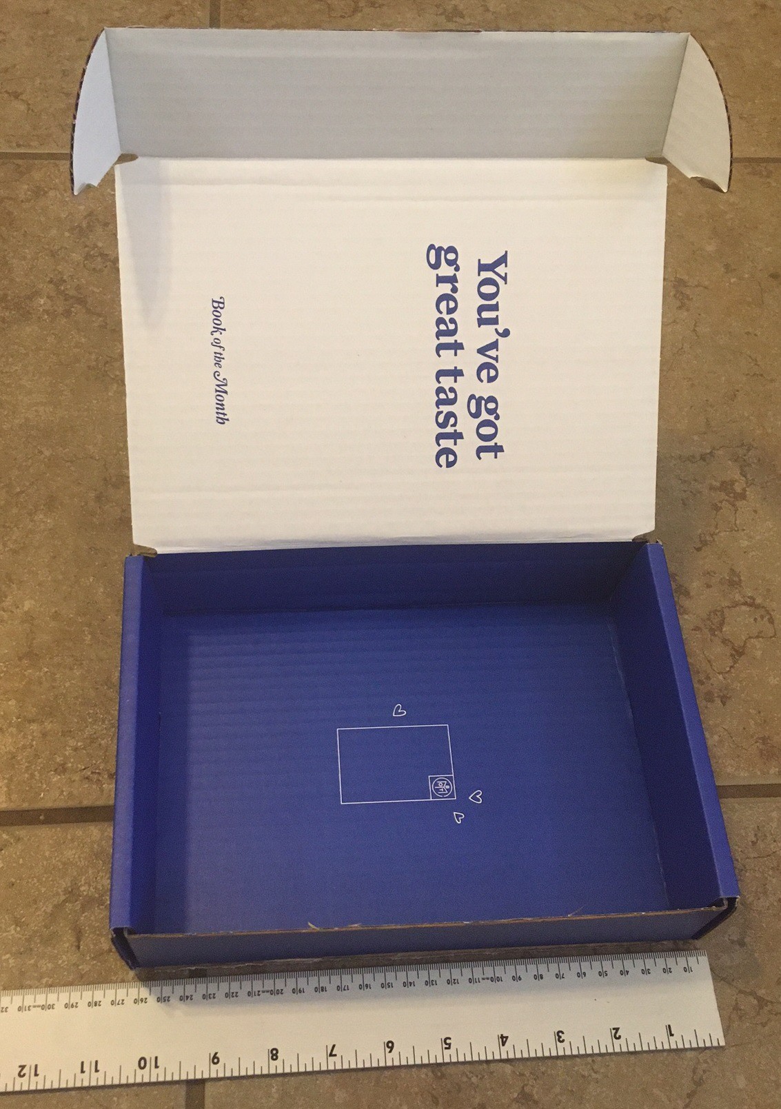
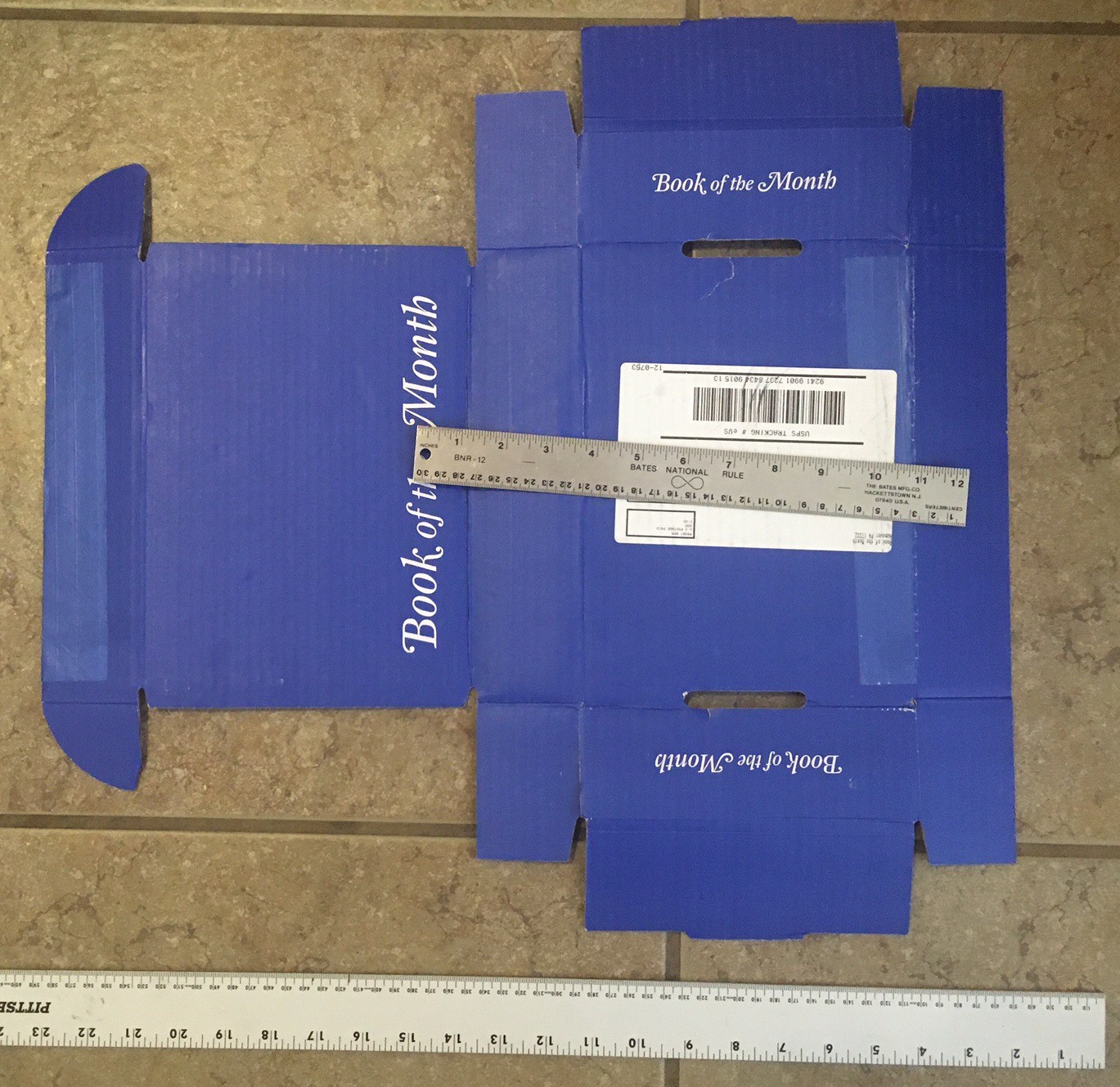
Book of the Month box
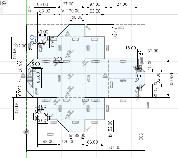
This box is 27 cm x 18.5 cm x 6 cm and is made from 2.2 mm thick corrugated cardboard. Like the Funco box it is designed to be assembled without glue, but it adds flaps on the side that lock the front and back in place so the box won't come apart on its own when the lid is released. The lid has an interesting tab system that makes it sturdy but easy to open. This box is made to ship and only requires a single piece of tape at the front to hold it secure in transport.
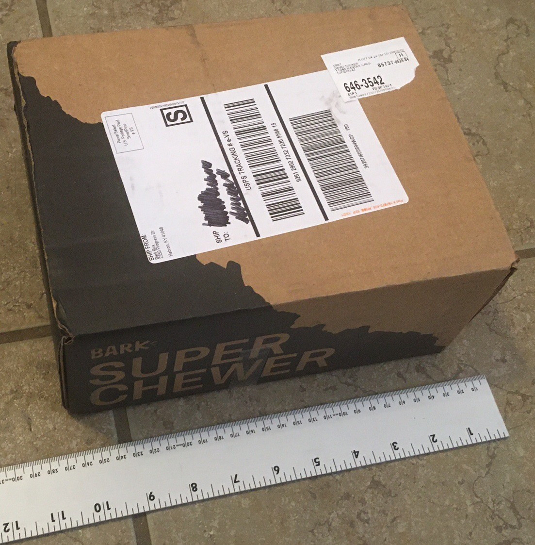
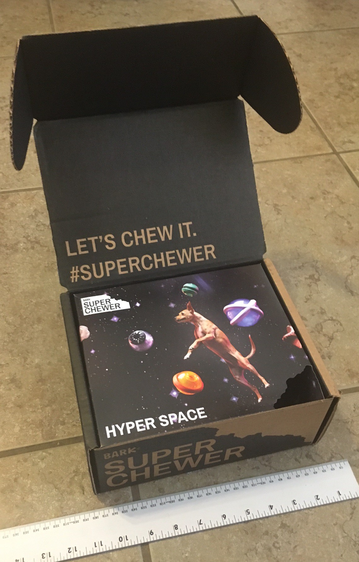
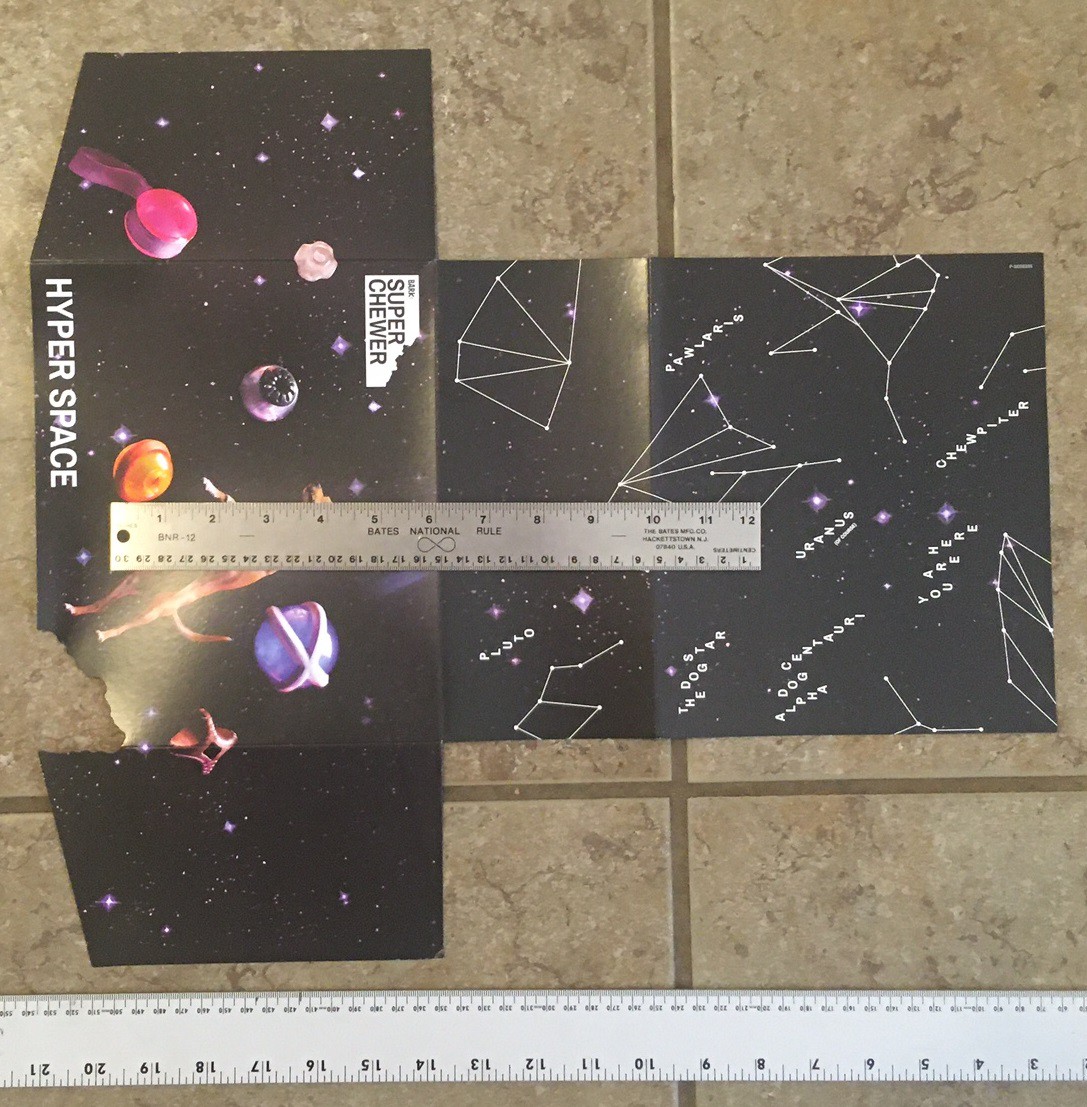
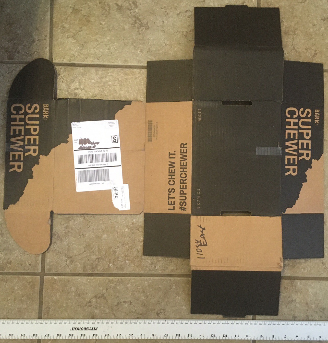
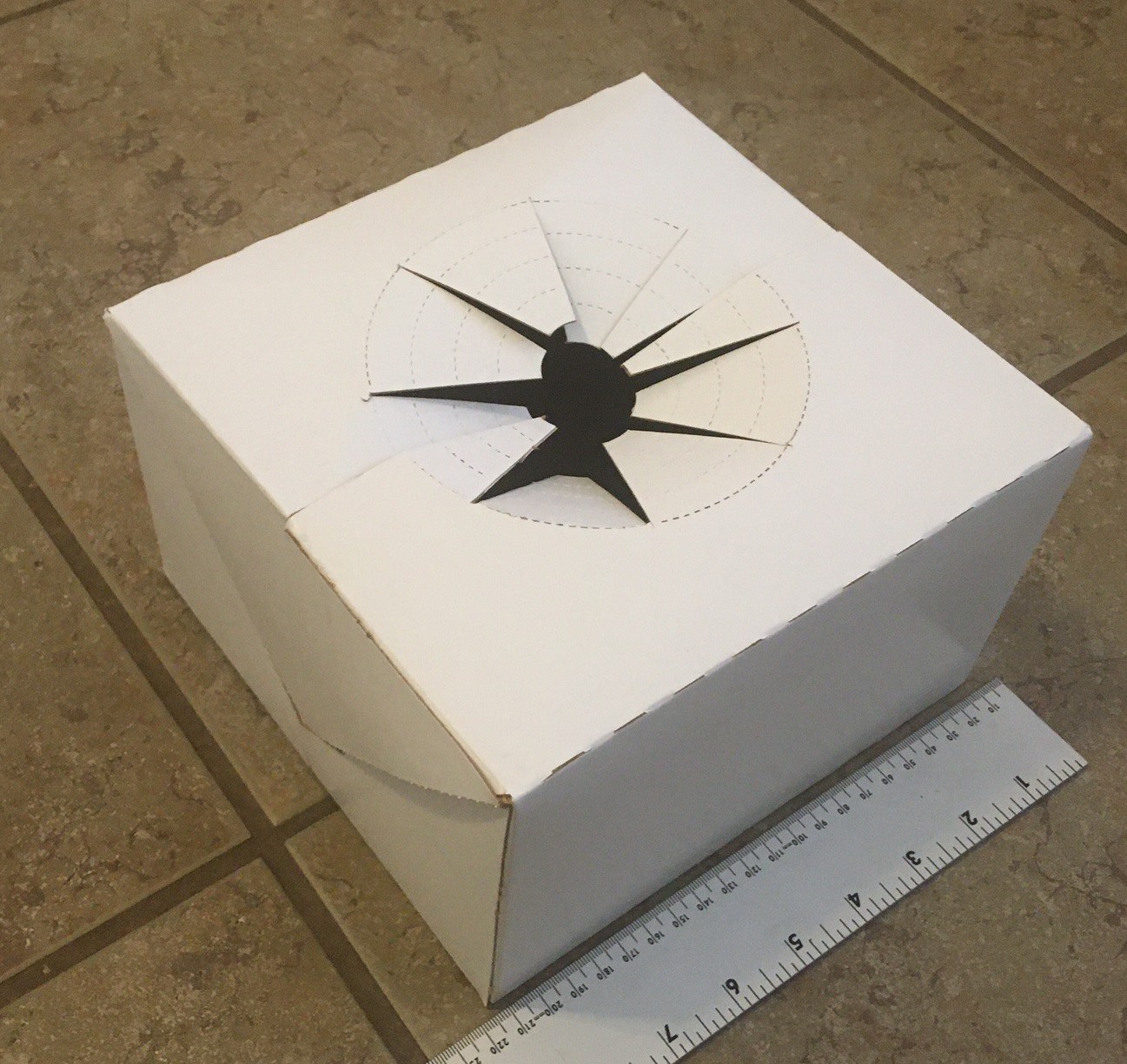
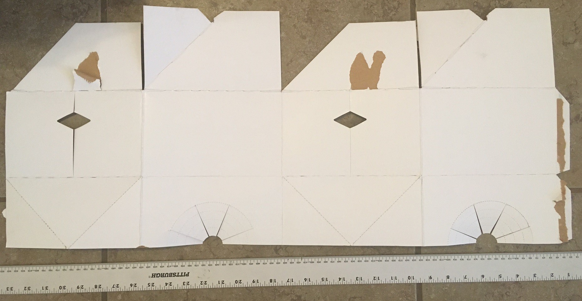
Super Chewer box
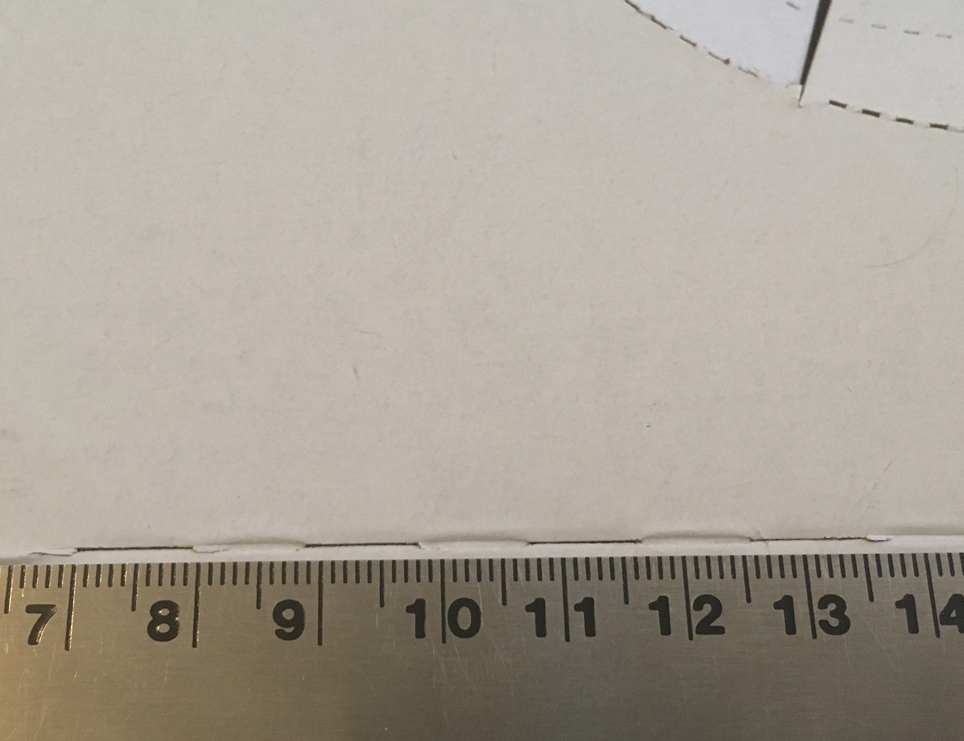
This box is 25 cm x 19.5 cm x 10x5 cm and is made from 2.9 mm thick corrugated cardboard, the insert is made from a 0.3 mm heavy cardstock like paper. It is very similar in design to the book of the month box but it has a unique custom insert to spice things up. It also ships as shown with only a single piece of tape to hold it together.
Vase box
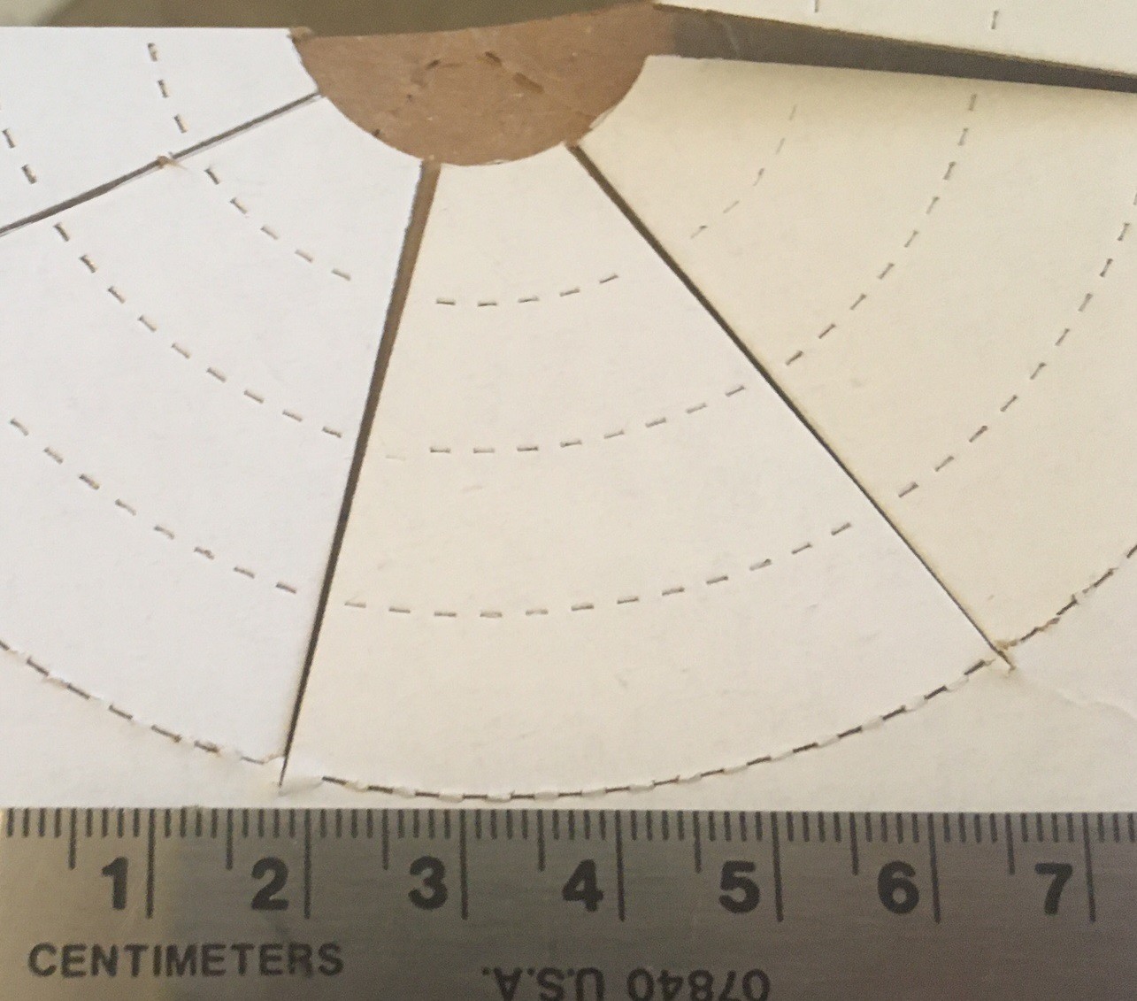
This is one of the more unique boxes, It is designed to hold a vase of flowers and is made to store flat and be easily assembled when needed. It has multiple glued edges, and unfolds almost like origami. It also has several perforations that were cut into it to make it more flexible. These were cut with a knife but could just as easily been cut with a laser. This is very similar to how a restaurant to-go drink carrier would be designed. It has dimensions of 20.5 cm x 20.5 cm x 12.5 cm and is made from 0.7 mm solid cardboard.
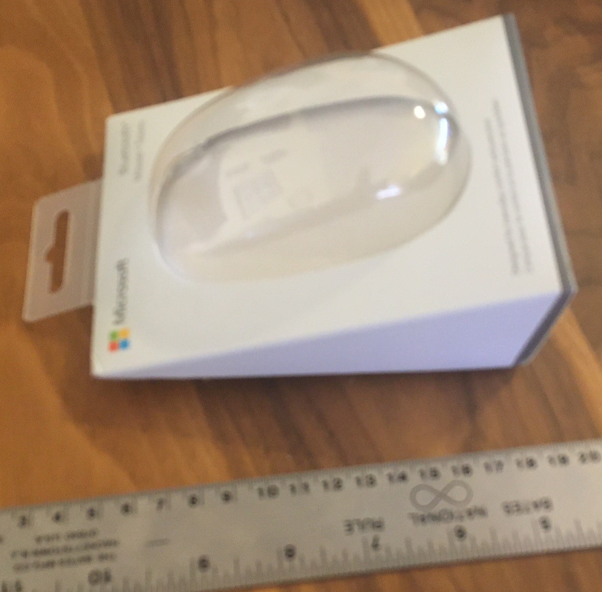
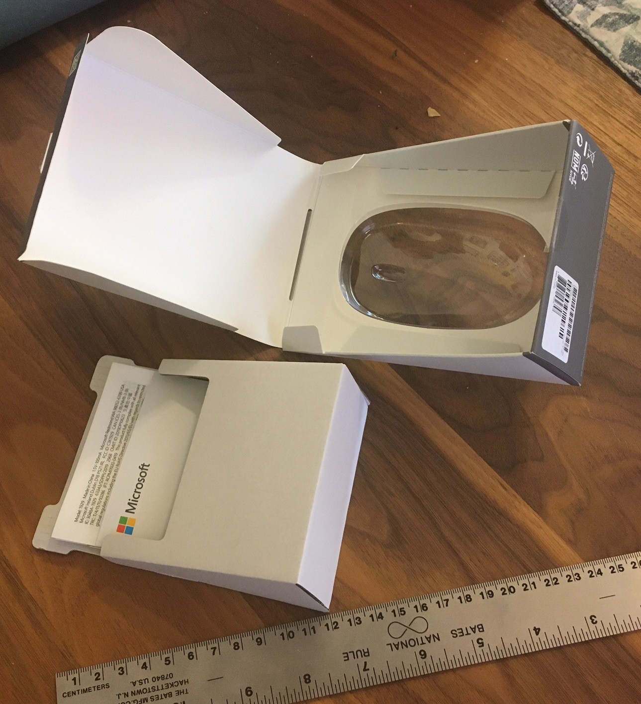
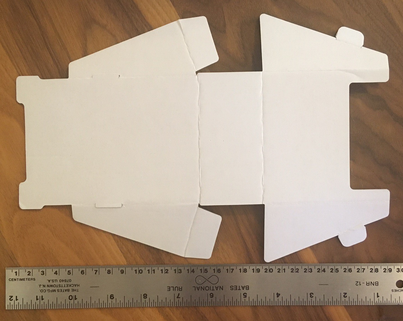
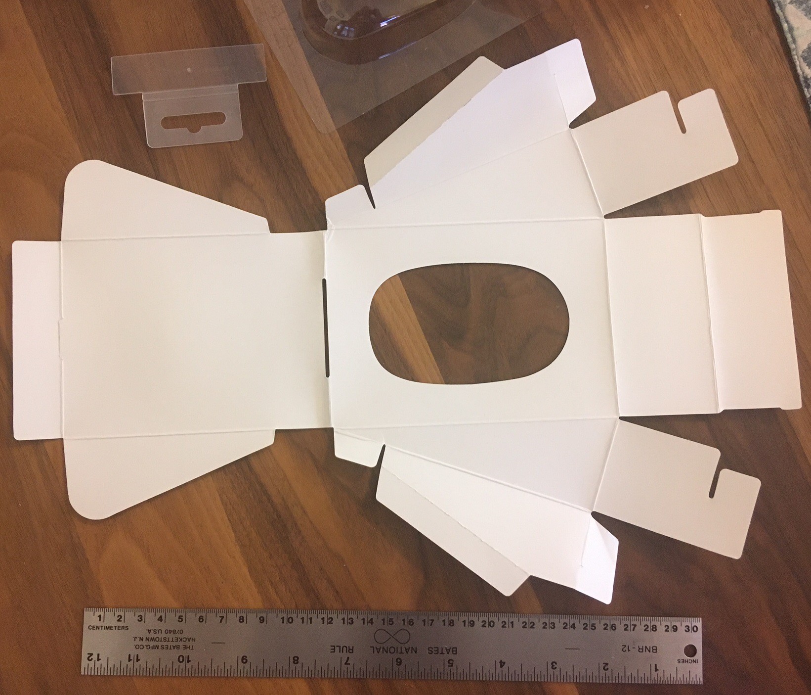
Microsoft box
Here is an interesting one, they manage to create a complex shape out of paper and some unique fold lines. It is also a unique mix of vacuum formed plastic and paper.
I have been thinking about air pressure (psi) and flow rate (cfm) and what it is we need to make all of this work. I think I found a relationship between the two. In our case we are trying to force air through a small orifice that seriously restricting the flow of air. So to get more cfm we need more pressure. Or to look at it in reverse, a given level of pressure and restriction at the nozzle will produce a fixed level of flow or cfm.
That means we can work out the ideal flow rate by pushing air through the nozzle at a given psi and measuring how long it takes for the pressure to drop in our tank. Then with a bit of math we can work out what the flow rate (cfm) actually was. Finally we can look at the available pumps out there and see if they can produce the flow at there peak psi we need to run the nozzle.
What this does not do for us is work out what pressure and flow rate cuts best, that we have to work out the hard way through trial and error.
So I have a 6 gallon tank and am using a 2 mm orifice. I let the tank fill up to its cut out pressure (150 psi) then timed how long it took to drain to its cut in pressure (120 psi) at various pressure levels from 5 psi to 30. I also measured how long it took for the tank to fill back to the cut out pressure while releasing air at the indicated psi. At 25 psi the tank was never able to refill. The table below summarizes my findings.
psi
release time(s)
fill time(s)
duty cycle (%)
CFM
5
130
53
29
0.76
10
63
63
50
1.56
15
51
94
65
1.93
20
43
180
81
2.28
25
33
infinity
100
2.98
30
28
infinity
100
3.51
That gives us a good idea of how much flow we need for a given psi of pressure and a given size nozzle. If we increase the nozzle size we will need to increase the flow rate for a given desired psi, so adjust this list based on your own setup.
Anyway we need to also work out how much pressure we actually need. To get a sense of this I made two tests. For the first test I cut a series of lines with the focus point set to the top of the workpiece in MDF at 50 mm/min and 80% power and varied the PSI from my air assist. I then used a 0.002mm feeler gauge to measure the depth of the cut by inserting into the cut, marking the top with a pen, then measuring the depth with calipers.
psi
cut depth (mm)
improvement (%)
0
0.8 (with heavy scorching)
100%
5
1.7
213%
10
1.7
213%
15
2.2
275%
20
2.0 (seems off)
250%
25
2.56
320%
30
2.96
370%
I'm not sure what happened with the 20 psi measurement, it seems off. However we can see that any air is miles ahead of no air, and more air gives better results. This data is really rough, my measurement method was not the best, however if you plot it out it appears fairly linear. What is interesting is that we get deeper cuts with more air without the kerf (width of the cut) getting wider.
For the second test I set the pressure to 15 psi, power to 80 and speed to 50 mm/min (as above). Then I did multiple passed lowering the initial focus below the surface.
focus depth below top (mm)
cut depth (mm)
improvement (%)
0
1.8
100
-1
2.3
128
-2
2.9
161
-3
2.8
156
-4
2.7
150
You can see from this data that there is a small improvement at first from lowering the laser but it has minimum benefit. Eventually the focus at the top becomes so bad that we end up loosing power. I'm sure that more air can help here. And of course multiple passes over the same cut are different and should work much better.
The farther I lower the focus depth the wider the kerf gets, using air pressure is a better way to increase the cut depth. With that said it seems like for now that I will stick with 15 psi of pressure and focus 1-2 mm below the surface or less than 1/2 the depth of the object we are cutting, whatever is smaller. That allows my compressor to run at a reasonable duty cycle that won't wear it out and yet it gives me a reasonable improvement in cut quality and depth. It would be nice to run at 30 psi but I would need a much larger compressor that is capable of 5-6 or more cfm at high pressures.
It looks to me like any air pump that can hit 4-5 psi and 0.75 cfm will get the job done, however it will not have nearly as much benefit for cutting as a stronger full sized air compressor can have. Going from 5 psi to 15 psi had a 50% increase in cutting depth. On the other hand for engraving we want to just put out the fire and not really remove any material. In that case I suspect that a (large) aquarium pump is more than good enough.
In fact my hypothesis is that any air flow above 0.25 cfm is probably good enough for engraving, including a small radial fan mounted on the laser head and blowing across the work like a part cooling fan on a 3D printer. However that is an experiment for another day.
 David Tucker
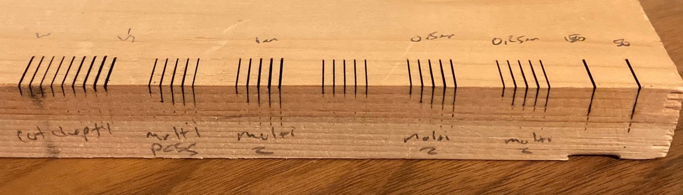

 —
—