We have a new puppy, she is very cute but really mischievous and will eat just about anything. So this year were decorating the tree with paper ornaments that we can throw away at the end of the season.
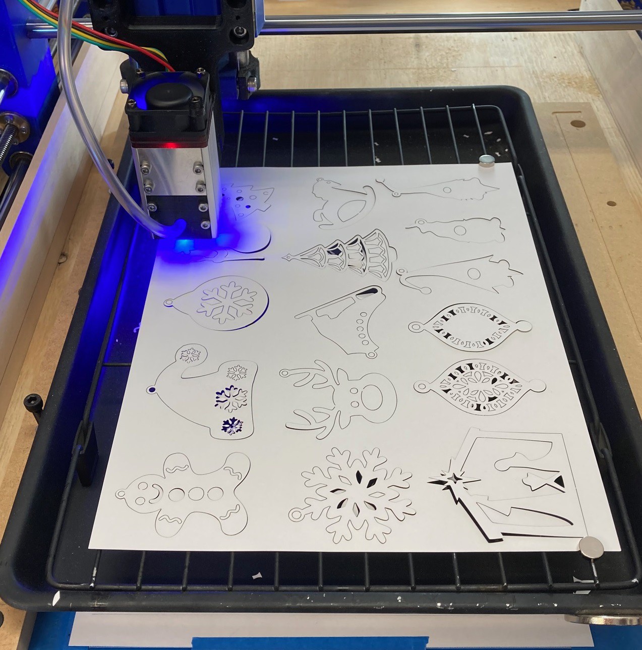
I decided to do my part and cut out ornaments with the laser cutter. I was originally going to try cutting them out with the drag knife but Fusion 360 had some troubles with my svg outlines. I need to come up with a better way to drive the drag knife.
I'm not going to hand out the svg file, these were all taken from the internet and I don't have the rights to them. However it is not hard to find your own images online.
I think it turned out really nicely, it still amazes me the amount of precision you can get out of a laser cutter. It is crazy, and beautiful. So Merry Christmas from Arizona!
If I ever have the opportunity to make a version 3 of my cnc I would make several changes to it. I thought it was time to document some of those tweaks now, while they are fresh in my head.
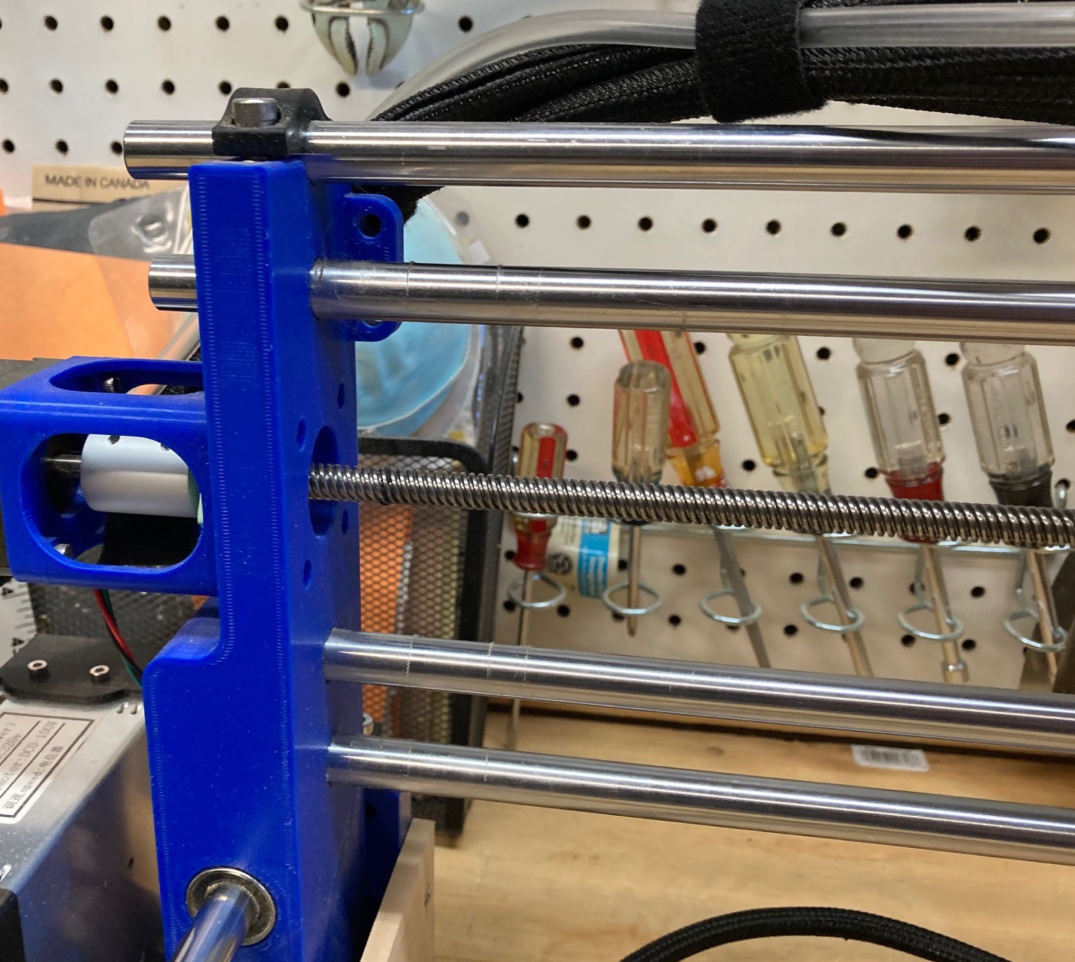
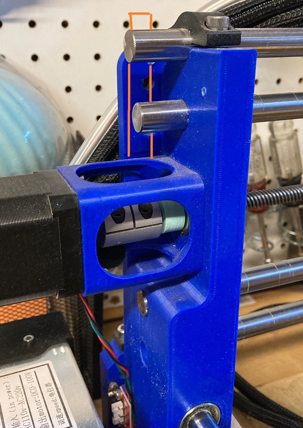
I would get rid of these 12 mm rods and go with a 16 mm rod on the bottom and either a 12 mm or 16 mm rod on the top. It will increase the cost a bit and make it a bit harder to source parts but it would allow me to make this larger and make things a bit stiffer as well. I have a pair of 16 mm rods and bearings to test out, it is possible that they won't be as stiff as 4 12 mm rods. I will need to test them out to see.
With new stiffer rods I can make the x axis wider and use the full width of the underlying board. I like this size base, it is just small enough that I can easily move it from inside the house to the garage without too much trouble. Going any larger would make it too heavy to lift and to large to make it through the door. However I could use the full 600 mm width of the board by moving the electronics to the bottom of the board. If I add some supports under the base board I can also use a thinner piece of wood and that may save a bit of weight.
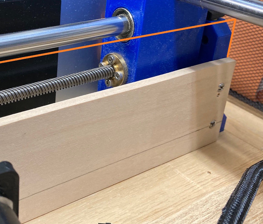
By raking the Y risers back a bit I can bring the spindle closer to the center of the axis and reclaim more of the working area of my y axis. I could potentially get another 50-100 mm of travel in the y direction this way.
It would be good to use a more symmetric and logical pattern for the hold down bolts under the spoiler board. Mine follow no logical pattern and that makes them less useful for future upgrades. I would guess that a pattern on 100 mm centers would be a good idea.
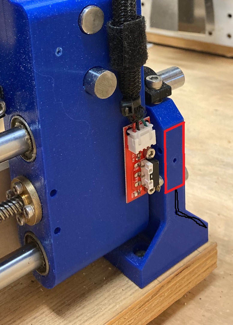
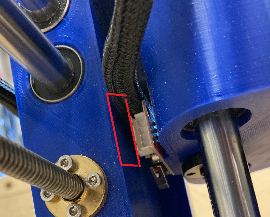
The limit switches were a bit of an afterthought on the original plan. I placed them because they were easy to put on, but if I moved them to the other side of each axis I would end up with fewer wires that need to move. In this case the Y limit switches could be moved to the base and not move at all.
The Z limit switch could also be moved to the x carriage so that the X and Z limit switch are attached to the same moving part, requiring only one bundle of wires to come back to the control box.
I did not capture a picture of it, but the Y stepper motors could move to the rear of the machine and a knob could be fitted to the end of each of the lead screws. That would make it slightly easier to adjust the position of the gantries when doing maintenance. I don't know that this is all that important.
The dust shields on the side are too short, they could come up quite a bit higher. I could also add a removable dust shield on the rear of the machine that attaches with magnets for quick removal. Those together would go a long way towards making things cleaner. A full enclosure would be even nicer but that takes us away from a portable machine.
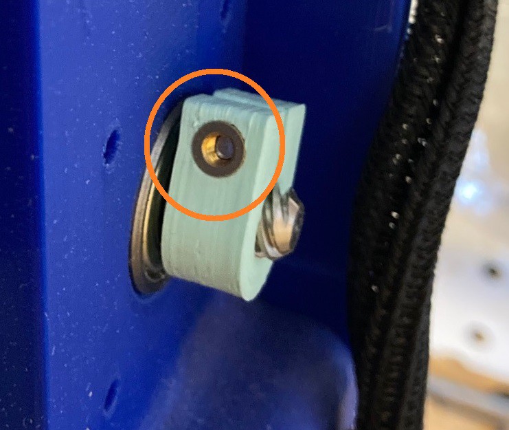
All the 3 mm heat set inserts could be replaced with captive nuts. A dab of glue may be enough to keep the nuts from falling out, or a bit of 3D printing creativity could help. I'm torn on this, on the one hand I really love the heat set inserts, but on the other hand they are difficult to source since every brand seems to be a different size.
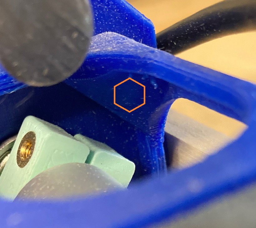
The 3 mm heat set inserts on the motor standoffs could also be replaced with captive nuts.
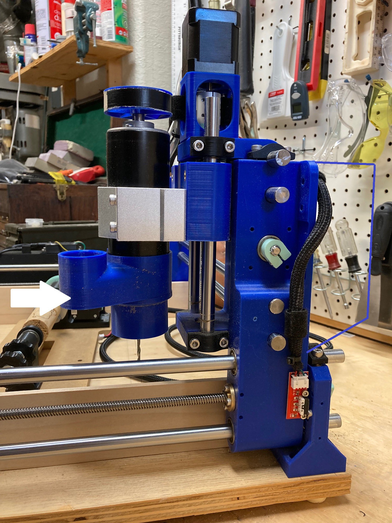
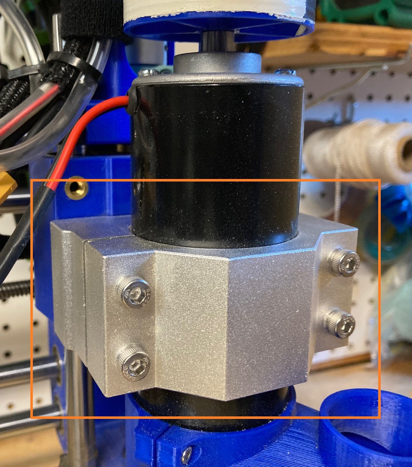
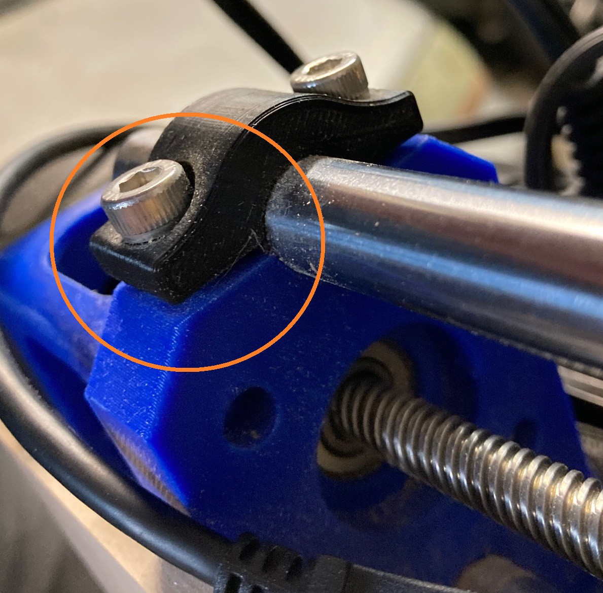
The motor clamp is not well made and I'm sure I could come up with a better solution. This is a poor compromise that makes all my other attachments sloppy because I'm trying to work with the stock clamp. The clamp should attach solid to the motor separate from its attachment to the machine. It would also be good if it was lighter, this is a very heavy part. I have tried in the past to make this out of PLA but it was prone to deforming as the motor heated up. I would need to make this out of PETG and come up with a better way to register it precisely with the Z carriage.
The Y base is a bit wide, I could shave some material off of it and recover a bit more range on the x axis. This is a small win, it may not be worth the compromise to the rigidity of the machine.
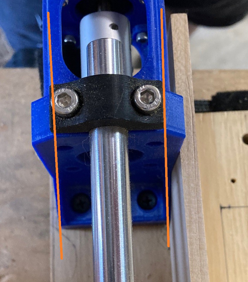
The Y uprights are beefy but not as beefy as they could be. More material could be placed here. And with a bit of work I could come up with a way to clamp each of the bars rather than just clamping the top bar. Using captive nuts rather than heat set inserts for the 5 mm bolts would be nice as well.
There is no way to really synch down the nuts for the bar clamps. I had a set rattle loose the other day mid cut, fortunately the bar itself was still held captive and the cut was not lost. These have a lot of flex to them so it is hard to make them clamp tight, it is possible that with a bit of better engineering I could come up with a stronger clamp. Another idea would be to use lock nuts, or Loctite on the bolts.
Anyway that is all I could come up with so far, I'm sure there are other ideas that would be good to look at as well. I will try to keep this up to date as new ideas come to me.
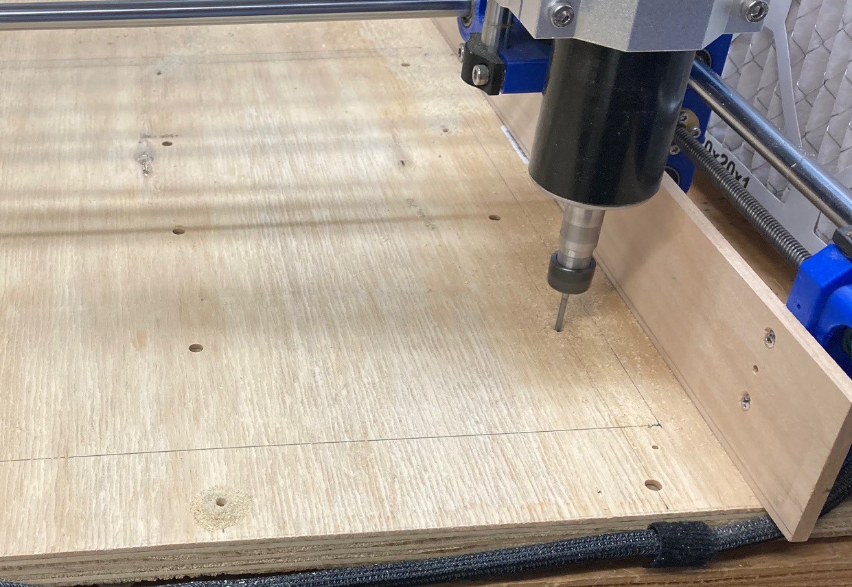
I'm getting closer on my rotary axis. I finally found the time to sit down and make all of my cuts. First I added in holes in my baseboard between the existing holes I cut to hold down my spoiler board. This works but it is one of those areas where I messed up early and now I have to live with it. Initially I spaced the holes to match the spoiler board so there spacing is not symmetric or convenient. If I make a new version of the machine I will be sure to make a more uniform grid of tiedown points.
I then cut the same holes in the spoiler board to act as passthroughs. This is a perfect example of how an upcut bit works, it pulls all the sawdust up out of the cut almost like an ant hill.
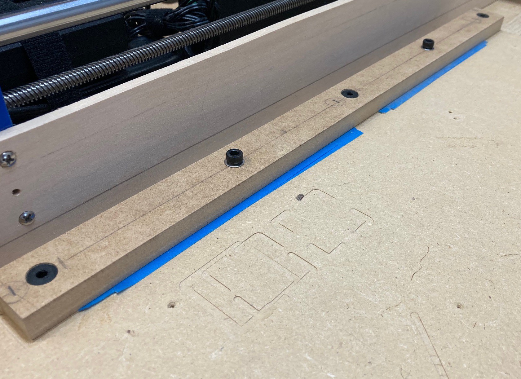
Finally I tried out the CA glue and painters tape trick to put corresponding holes in my fence so it can be held down better. The CA glue trick worked much better than I would have thought. It holds things down with just enough force to get the job done but does not hold so tight that pulling the part up is a pain.
Again if I had to do this over again I would change things around. I would use 2 reference pins to hold it in place and put the hold down screws at the edges. I would also try to use more holes so that it would be easy to add in a corner bracket that does not take up a lot of room. And finally I would experiment with using beveled heads that can be countersunk to better hold this in registration, right now I can move the fence a mm or so before tightening it up. This is not a huge deal, but it would be nice if the fence was more accurate.
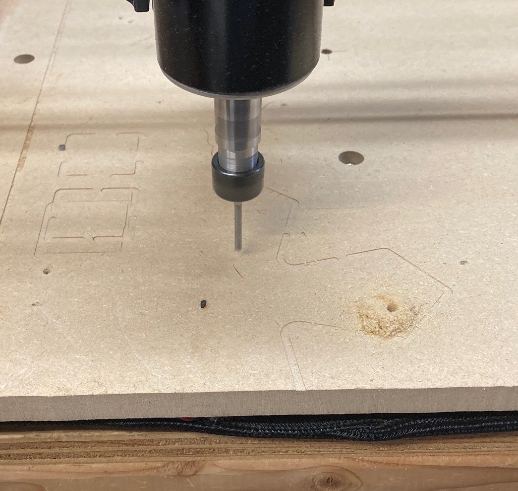
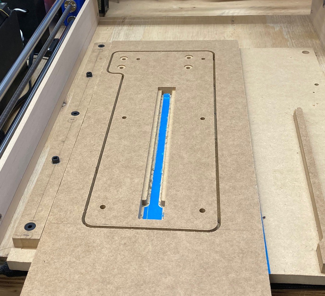
Finally time for the big cut. Again I used the CA glue trick. It worked well but it only took a tiny bit of force to remove the center cut. I was trying to minimize how much CA glue I used and I don't know that any of it ended up under this cut.
It just took a tiny bit of sanding and now it is all ready to be assembled. I really like the precision of the CNC, it is so much better than trying to cut things out by hand.
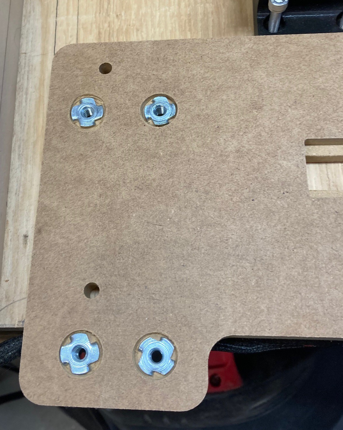
I measured the counter sunk holes wrong and they ended up too small and too shallow. I had to use a spade bit in the drill press to enlarge the holes. It made a bit of mess but at least the piece was saved.
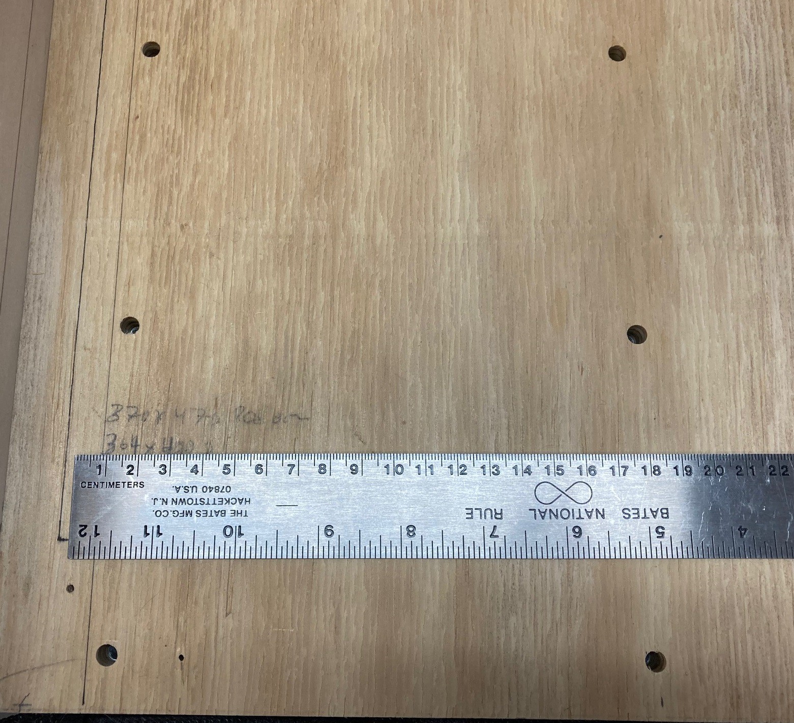
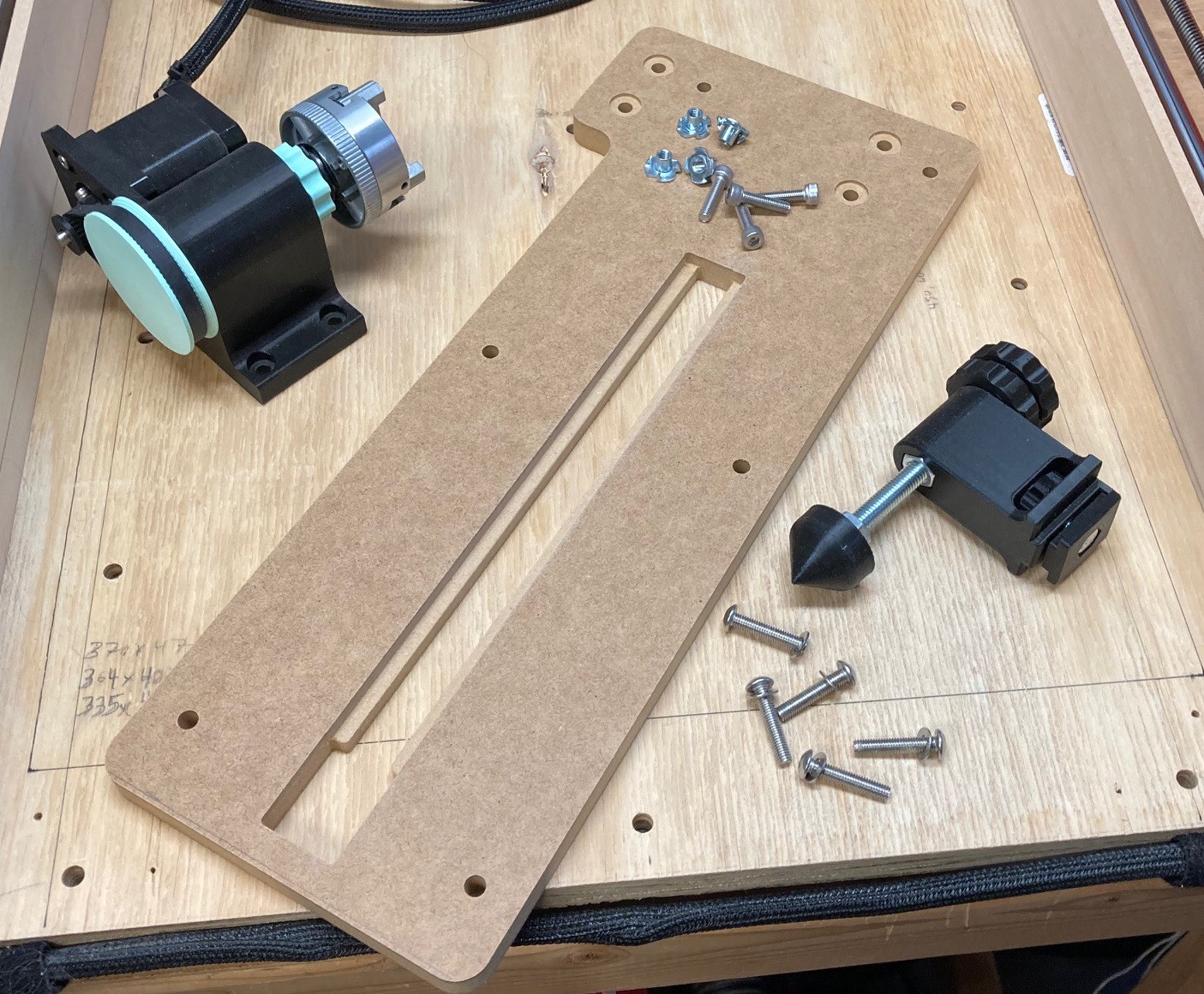
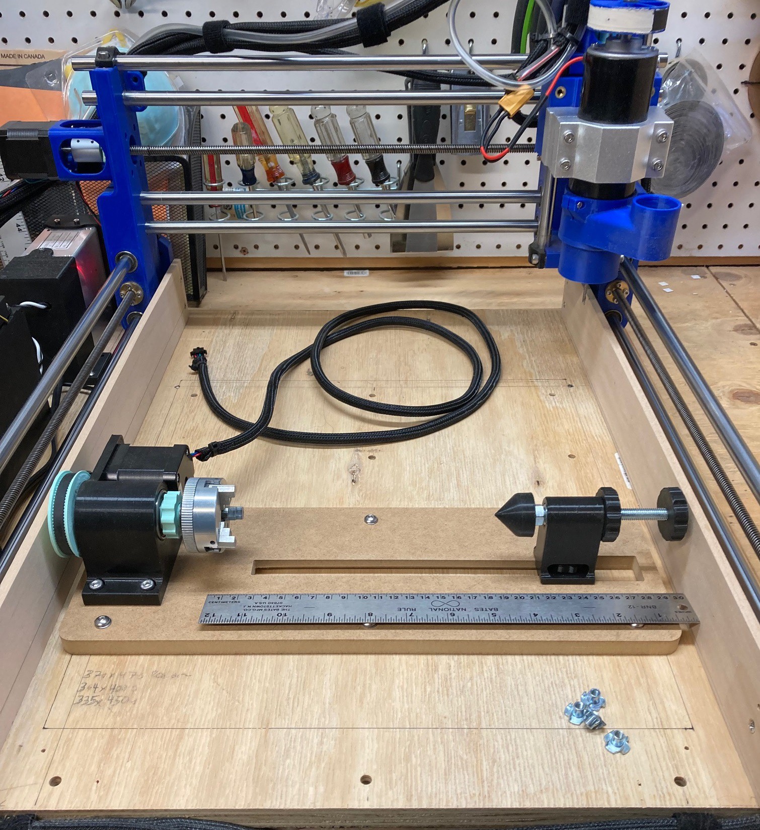
It all fit together in the end, I ended up with a maximum working distance of about 19 cm, that is not very much but it should be enough to experiment with. I wish it was the full 46 cm of working distance in the y direction.
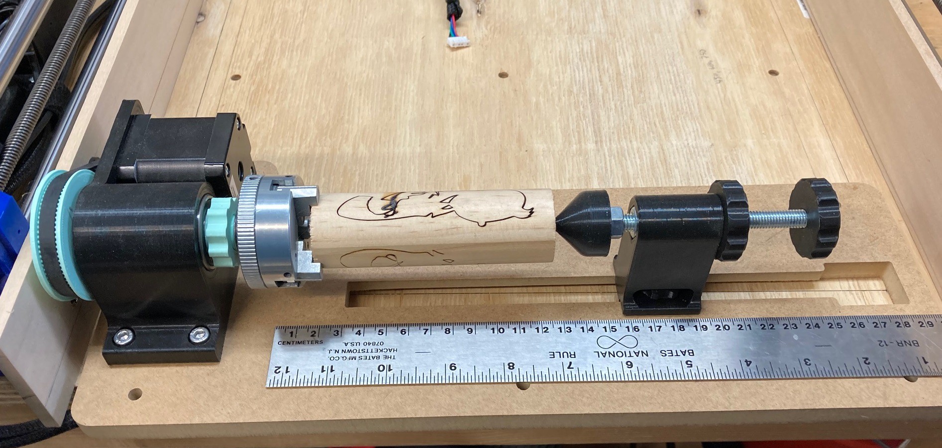
I chucked up a quick piece, without drilling a hole for the tail stock. It has a bit of flex to it, so I probably will need to beef up some parts of it, but it has promise. I need to make a centering jig for drilling the hole in my test piece, I have a feeling that will help stiffen things up some. There is flex on both ends, I suspect that is coming from the bearings, or the bearing housings. Also the quill is a bit flexible as well, I may double up the bearing at the tip so the quill is better supported.
Anyway I need to get some longer bolts that can pass through the bed so I can tie this all down, and then I need to try some test cuts and see how well it works.
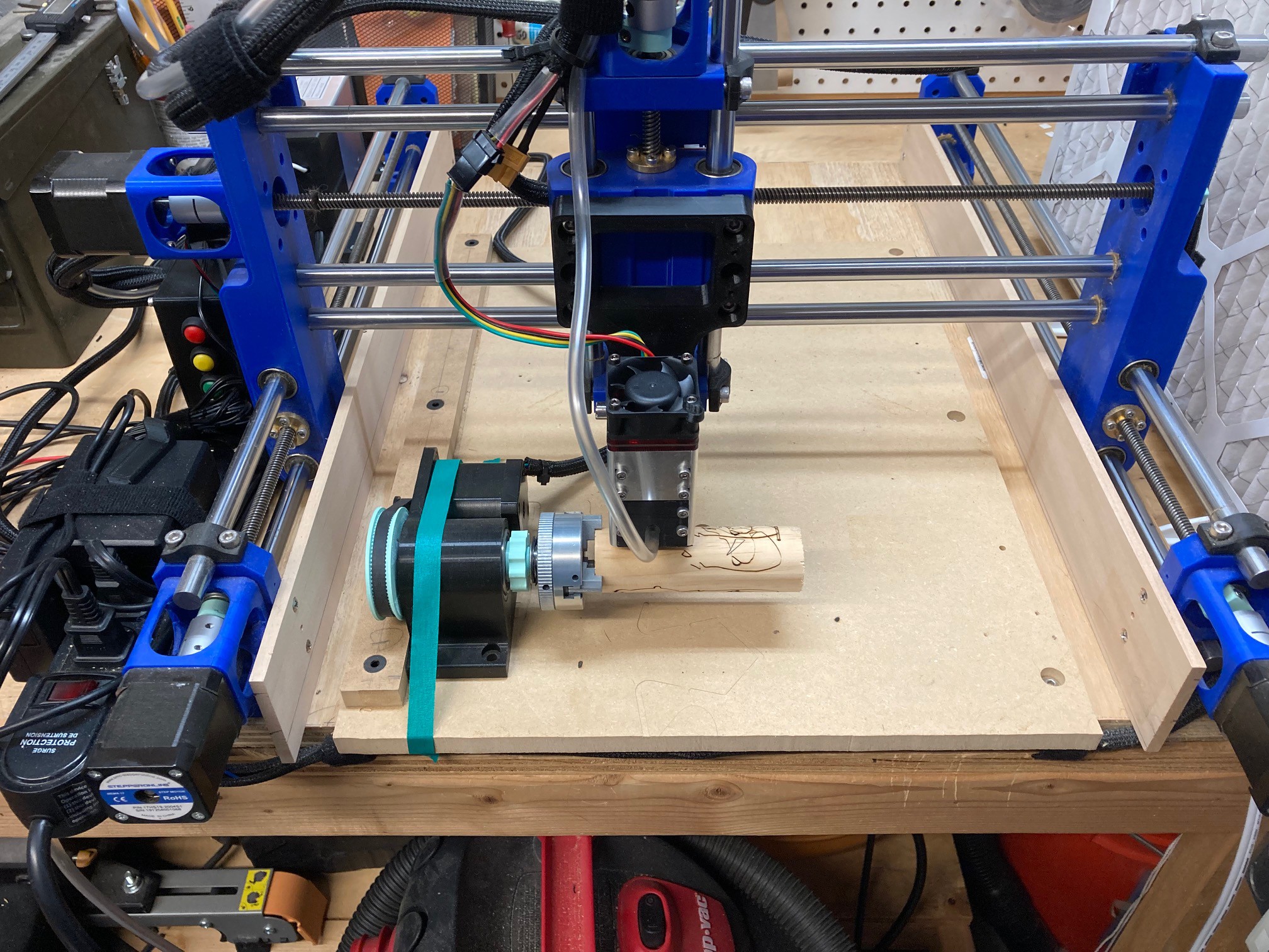
Things have been going slow recently but I did find a chance to test out the rotary in light burn. It is working great, given the aforementioned limitations.
I have redesigned my laser mount and have it ready to cut out. I just need to find an hour to play around in the garage. Maybe over winter break I can put this all together.
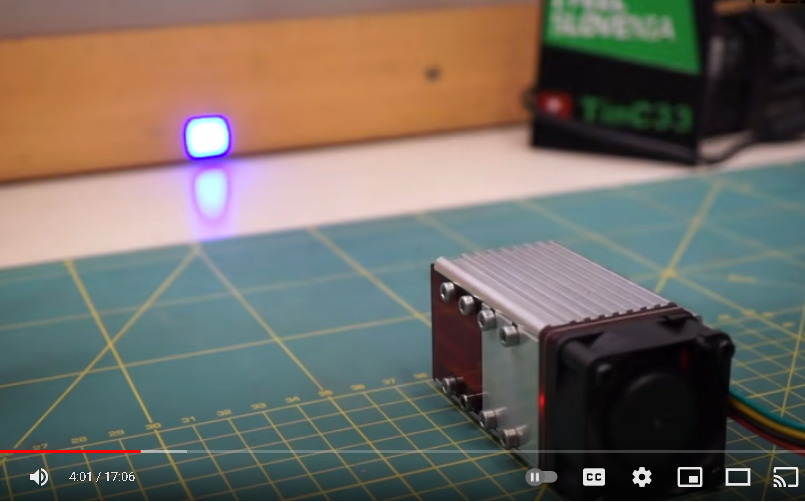
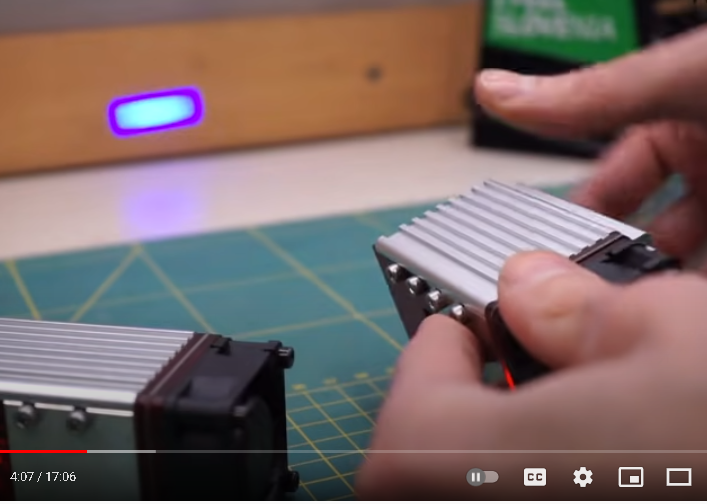
Here is a screen shot showing the unfocused spot of a NEJE A40640 40w module. You can see the spot is very square. Not shown here but it is actually burning a spot in the wood at this distance.
Here is the NEJE N40630 30w module at roughly the same distance. Assuming the focus is set roughly the same then it looks from this shot like the spot height is the same as the 40w module but the width is 3x smaller. That should represent a 3x increase in optical power in theory, assuming the FAC lens is not cutting the power down. In practice I suspect between the FAC lens and the beam splitter the laser is loosing 30% power so were probably only seeing a doubling of power here. Coupled with the beam splitter were getting close to 4x more power than my 30w module.
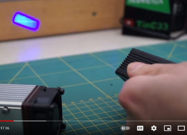
Here is a 20w module, I'm guessing it is the N30820 module. It has a similar spot size to the 30w module and probably uses the same laser diode. Assuming all three were run at the same power percent, then it appears from the brightness of the spots that the 40w module is outputting a lot more power. Someday I will get my hands on one and compare it.
Lightburn is one of the most frustrating programs I have ever used. It is very close to being an excellent program but some odd ideology really holds it back. I have written previously about my frustrations with it not working with a standard negative CNC coordinate system.
Now I'm trying to get the rotary axis working and they only let the X axis be the linear axis, while the rotary axis can only be on the Y, Z, and A axis. And if you add the rotary to the A axis then they insist on the rotary turning exactly 1 degree for ever full unit of travel.
In this case it is going to force me to severally limit how long of an object I can turn on the rotary. I will probably only be able to handle 6" long objects in this configuration. If I could use the Y axis for the linear axis then I could use the full 460mm (18") of motion to laser the object, and I could support a piece that is infinitely long, assuming I could find a way to support it across the whole length.
Both of these problems are not technical ones. Making a transform to let you use negative coordinates or use a Y axis in place of the X is trivial, only a few lines of code. The problem is the authors dedication to there ideology that there is only one right way to configure a machine.
This is a problem I see all over the place, ideology (rules of thumb that guide us) are used without thought. I often hear "Buy once, cry once" on forums, but while that is not terrible advice it is far too generic to just apply to your life. What if your trying out a new tool that you only need to use once, or your budget is very limited, or your not using the tool in a professional capacity. All of these are legitimate reasons to buy the cheaper tool rather than investing upfront in the expensive one. The world is messy, and while one idea may be the 'only way' on paper, that does not mean we need to be a slave to it. Sometimes being flexible is much more valuable than being right.
I should have done this a long time ago, but I finally got smart and uploaded my CNC firmware to github so you can download it directly rather than having to recreate my modifications on your own. For every file that I have modified, I included the original file next to it. That way you can see just what I have changed easily without needing to pull the original version of the files.
There are two different repositories. One is my last version of my grbl build for the uno and cnc shield. This assumes you have a new protoneer shield or have modified the chinese shields to be compatible with the latest release. There is not much changed in this version, it is probably best to look at the changes and then work out for yourself if they fit your setup.
The other setup is my new grbl-mega-5x port for the mks gen l v2.1 board. This is a more extensive modification. I had to reroute several pins so I could use the thermistor inputs for buttons, as well as turning the negative y limit switch to an 'a' axis limit switch and moving the probe pin to the negative z limit switch. Finally I have modified it to support auto homing and a 4th axis rotary attachment and of course configured it all to work with my machine.
Again these changes are very machine specific, so I recommend looking at them closely to make sure it matches your machine. However it is complicated enough that I don't feel a line by line writeup would be enough to get you going, hence the repository.
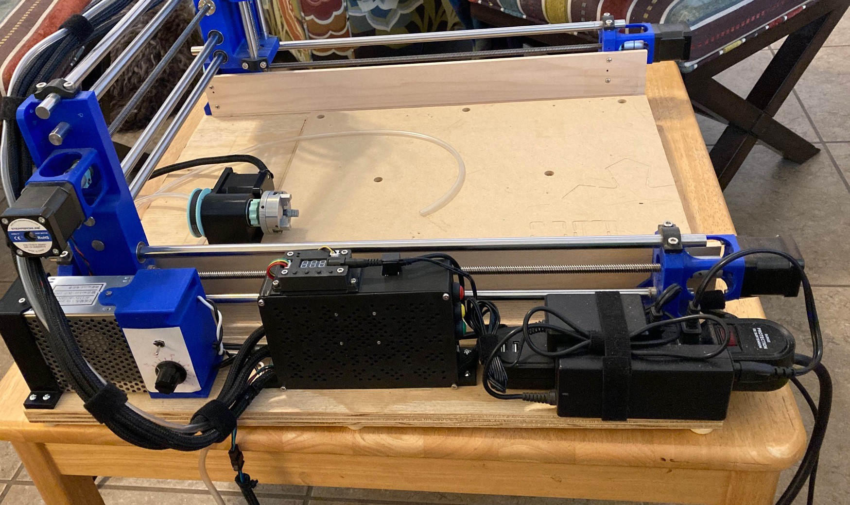
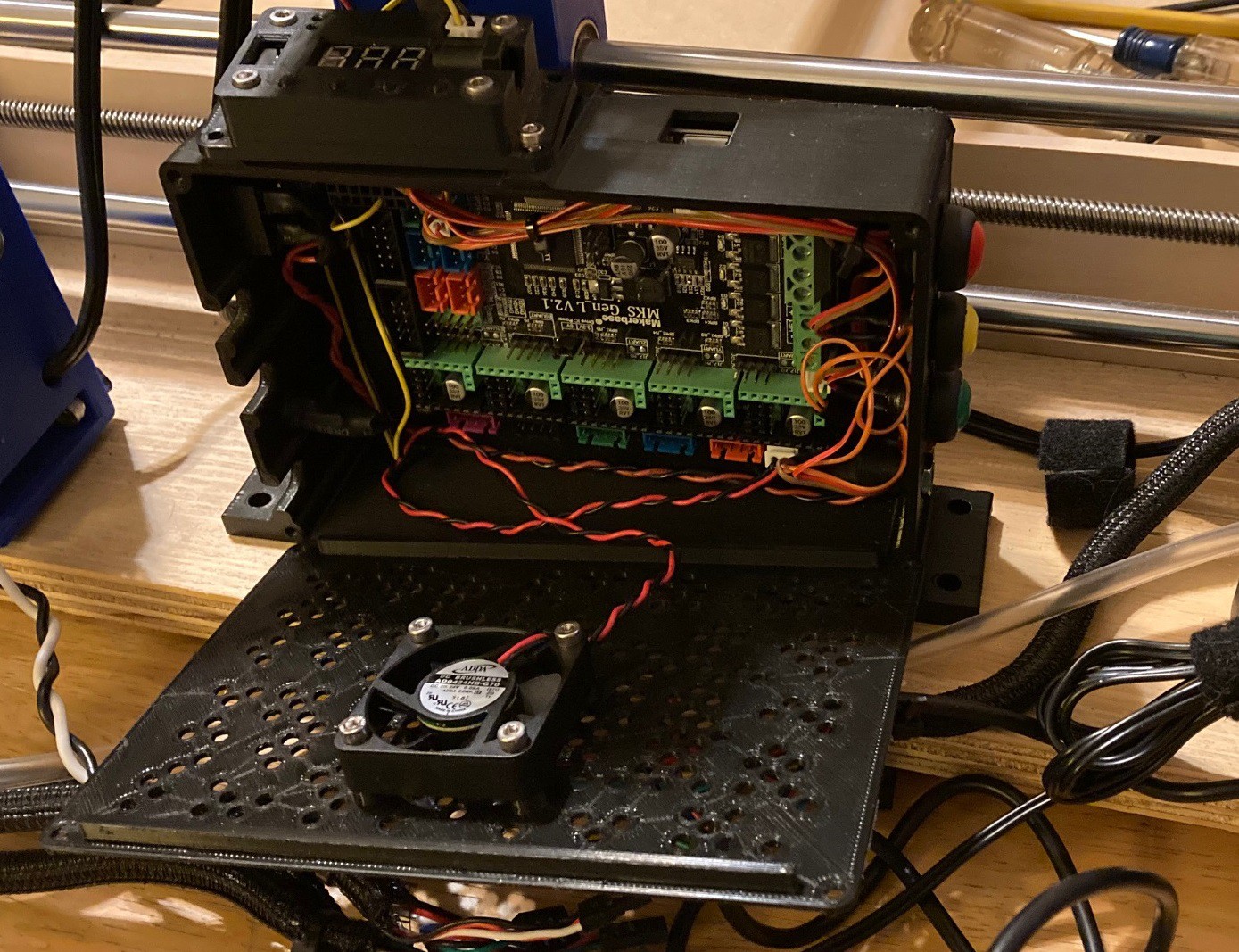
So after way too much time and effort I have successfully moved from a GRBL CNC Shield to a MKS Gen L V2.1 board. That allowed me to go from 4 drivers to 6, upgrade to a slightly stronger processor with twice the memory, and use an all in one board that is roomier and that uses locking connectors on most pins. All this just to add a 4th axis to my machine while still keeping support for auto squaring the y axis using two motors.
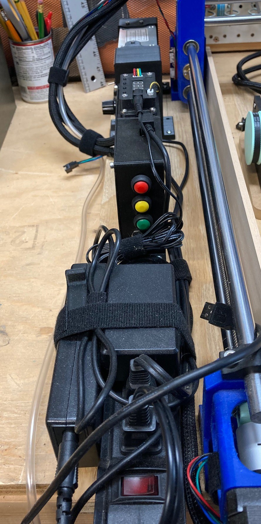
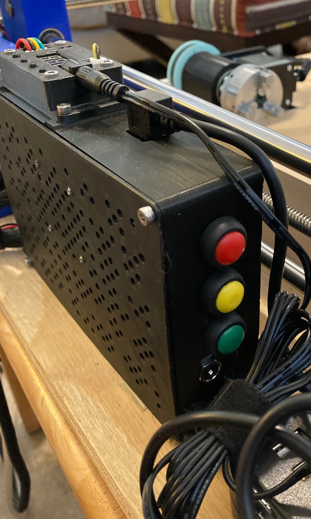
While I was at it I decided to add in the standard halt/pause/resume buttons for a GRBL machine, just to try them out. And I added in a headphone jack so I could wire up a touch probe to the machine as well.
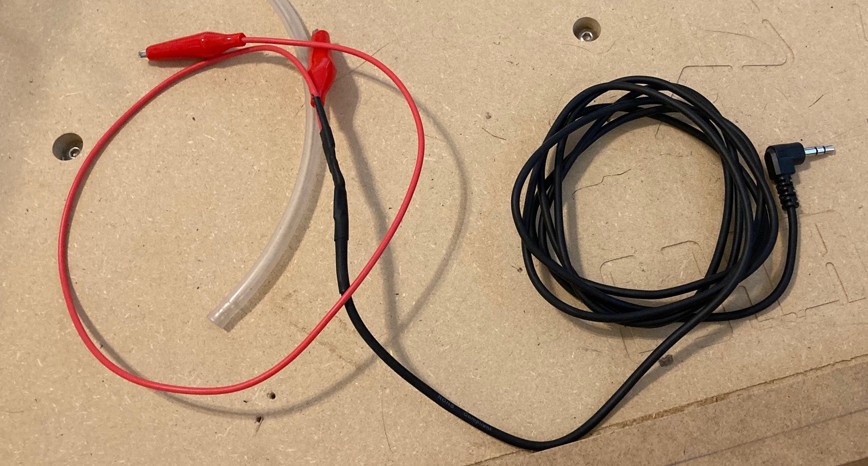
For now my touch probe is just a length of headphone cable with alligator clips on the end of it. When I find the time I plan on machining a proper aluminum block so I can find corners accurately. In the meantime I will probably clip this to a piece of steel or other scrap metal.
I had this wired up with power going to the tip of the headphone jack. My hope was to add a LED light to the end of the touch probe so it would be very obvious if this was working right. However when removing the jack there is a momentary short between all the pins and that causes the controller to reboot, so that had to go. It is a good idea still, but I need a different connector on the controller side. To make up for this I added an LED light at the controller side, it is not as visible but it does work.
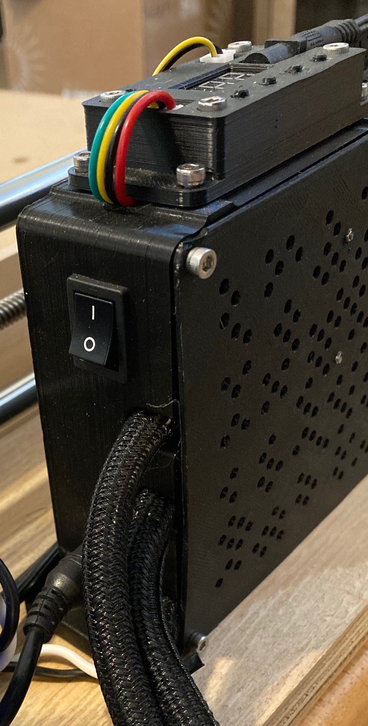
On the backside we have power and a power switch, and of course all the cables going to the gantry come out here.
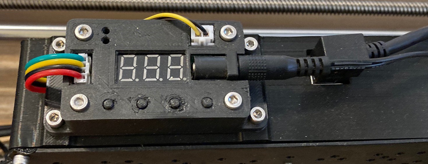
Up top I added my laser control board (which could use a reprint) and I ended up grabbing a right angle usb connector as well so that the cable would not stick up too high and interfere with the gantry.
I decided to stand the board up on its side so that I could have plenty of air flow on the front without much risk of chips flying into the control box. I have a 40 mm 24v fan mounted to the lid to help with air flow. I was unable to mount it close to the heatsinks on the drivers but my hope is that it will produce enough flow to help anyway. The lid is a weak spot, it is not very thick or sturdy, it could use another design pass, but for now it gets the job done.
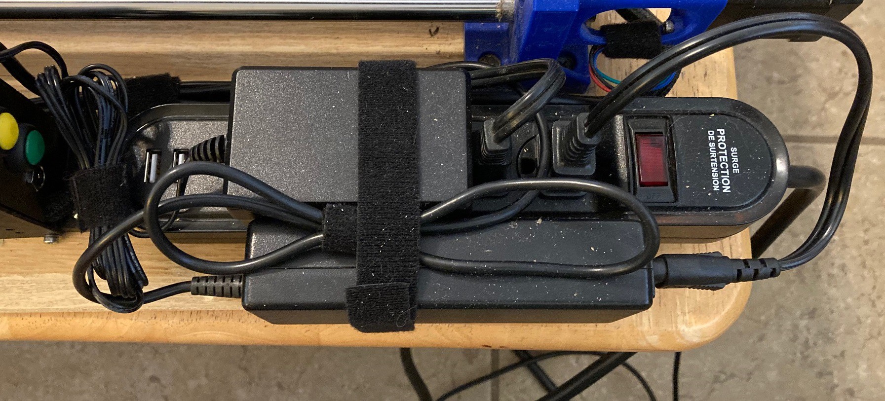
Finally I added in a new 4 outlet power strip with a pair of 5v USB jacks at the end. I figured the usb jacks could be used to add lighting or some other accessory (raspberry pi, etc.) at some future time. This strip comes with convenient holes in the bottom so I could secure it to the base, and I located the on/off switch at the very front of the machine to act as an e-stop as well. It is amazing how much work wiring is, most of the last several weeks were spent on wiring, or avoiding wiring.
I'm going to go ahead and upload my plans for the controller box to thingiverse. I don't know how much value it has for others, it has very specific holes cut out for the power and buttons and they are not all from the same shop. And I will upload my modified GRBL code to github as well and talk about the modifications in a later post.
The big question is, was all of this worth it? Right now I'm feeling like it was not. We will see once the rotary is fully up and running. I say this because it is much more complicated all the way around to put together and it cost more than a $15 cnc shield and Uno from china. The GRBL-MEGA-5x install does not just work out of the box, the wiring must be changed to work with the board (and cheap crimp tools stink), and of course it cost more and takes up more space. It is just a lot more work, for only a few limited improvements.
On the up side it is better put together, and I would be very disappointed to see a CNC Shield in any machine that I paid money for. This is undoubtedly a more professional setup, and if you were in the business of making a machine then customizing the firmware and making a custom wiring loom would be expected. And of course it does what we wanted it to do and adds in an extra axis for us to use. In fact with a bit of work we can add a 6th axis now as well.
I'm getting close to having my new controller up and running. I have a case printed up that seems to work (so far), I have GRBL-Mega-5x up and running, and I have (almost) finished the wiring. I just glued the heatsinks on my drivers and am waiting for them to dry. And I need to make a quick disconnect cable for the rotary axis so I can unplug it without opening the controller case.
The new setup has a few small changes from the old one. I added in support for a probe to make it easier to mill pcb's and for more consistent tool changes. I added in the stop, pause, resume buttons. I don't know if these have much value, but I was curious about them. And I removed the negative side limit switches from the machine. It can now home and use soft limits but no longer supports hard limits. The hard limits were never stable and since the controller only supports 6 switches this allowed me to use the 4 I still have without a daughterboard.
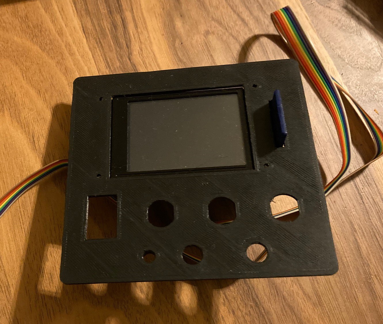
I received my MKS TFT24 LCD display and added the CNC firmware to it. This was another experiment, but It is not looking very good. The layout is poor and not very convenient, the display updates slowly, it has no feedback (status), and there does not seem to be a simple way to edit the underlying code. It is a shame that they did not make this Arduino compatible. This is really nothing more than an arduino with an LCD display and a flash drive. It should be trivial to make our own firmware for it. However from what I can tell no one has successfully done this. Anyway I will know more once the machine is up and running, but it is not looking promising.
Finally for a future project I have ordered two 800 mm long 16 mm steel rods and a pair of LM16LUU bearings. I want to run some tests to see how much stiffer these rods are than 12 mm rods. And I have an idea that I can replace 3 of the 12 mm rods on the X axis using only one 16 mm rod at the bottom and one 12 mm rod at the top. My theory is that this would be stiffer than my current setup while being cheaper than buying 4 12mm rods and bearings.
I have been thinking about shipping costs recently and how they are skewing the way we shop. Here are a few examples, for what they are worth.
My wife and I sent a package to a friend filled with books. It was a reasonably small package, less than 1 cubic foot, and weighing less than 15 pounds, but the cheapest we could get it to our friend was $45. My heart stopped for a moment when I saw that, we could have bought everything in the box new and had it delivered from Amazon for less money. More interestingly 10 years ago we could have wrapped each book in brown paper and sent them by media mail for less than $3 a book. Sending personal items through the mail is going to become a thing of the past soon.
Ages ago Amazon would charge you a fee for shipping. Then over time they played around with various schemes until they got everyone hooked on prime (paying a flat fee upfront for shipping) and that seems basically set in stone. I have noticed over the last 20+ years of Amazons growth that as the have moved towards 'free' shipping they have also moved to limit there minimum order size to about $10. It is nearly impossible to buy an item for anything less. I can buy one item for $10 and 10 of the same items for $15, but I can't get them cheaper. This has changed the dynamic when you need small items like screws or electrical connectors. Spending $10 for 5 m3 bolts and another $10 for 10 m3 nuts is a crazy way to do business, especially when you can turn around and get 100 m3 bolts for less than $20. I'm now starting to think twice before going to amazon when buying small items. It may cost me $1 per bolt at the hardware store (for metric fasteners) but at least if I only need two or three I'm money in the bag and I got to enjoy a stroll through the store as well.
Recently I placed an order from Jameco Electronics for some buttons and connectors. I had looked at Amazon but as I said above it was $10 for 2 buttons and I wanted several different looking ones. It was wonderful seeing parts listed for $0.10 again and being able to mix and match to my hearts content. However when I got to the checkout with my $14 worth of stuff I got a notice about having a $20 minimum order or they would charge me something crazy like $10 in handling fees. On top of that shipping and taxes were not factored into the price so everything was appearing artificially lower in cost. A quick search around and I found something for $9 that I did not really want but would rather have than a handling charge and away we went. The frustrating thing is that if they had just rounded up my order to $20 I would have been ok with it. It would have still been a better deal than amazon, and since the demise of RadioShack there really is no good local source for electronics parts in my town.
What I would like to see is a service that has a sliding scale on shipping where they are not hiding the cost up front in a $120 a year charge for the service like prime, and where there is still strong incentive for them to offer you small items that are counted out rather than having even the smallest things cost $10. Using a sliding scale where I'm rewarded in lower shipping and handling charges for larger orders (and slower delivery times) would incentivize me to save up my purchases and make the whole system run more efficiently. Amazon had something like this years ago and it was really nice, they even had 'add on' items that were only a dollar but could only be added onto the order. This was a bust because you could not order 10 add on items alone, but that was just a procedural issue on there part. The incentive was there to be careful with my orders but at the same time I felt like I was truly getting the best deal. Now I feel like I'm paying for the convenience of not leaving my house, and not really saving much money along the way.
 David Tucker