David Tucker
-
Slow Progress
10/24/2021 at 22:15 • 0 commentsPosts have been slow recently, but not for a lack of trying. I have been pulling many different GRB and Marlin variants out and trying them on my new MKS Gen L v2.1 hardware, but so far each has its downside.
- Marlin 2.0 looks great on paper, but it does not seem to be well supported by gcode senders commonly used with CNC machines. It also does not have a lot of dedicated CNC support, for example the asci displays seem to be heavily geared towards 3D printers with no options to repurpose it.
- GRBL has no support for a 4th or 5th axis and does not support any other board than the uno and cnc shield. This is frustrating, they could have easily added support for all the 8 bit 3D printer boards out there. It also has no support for displays or SD cards so there is no simple way for offline control of the machine. GRBL also has no support for serial control over the stepper drivers so you can't use stall detection or higher resolution micro stepping.
- GRBL-MEGA is not in active development and does not support auto squaring of the Y axis when using two motors. It is several revisions behind GRBL and has nothing to offer us other than it works on a Mega (ramps) board. This should be merged into the base GRBL project, but sadly it is not.
- GRBL-MEGA-5X does have auto squaring support, although it is not well configured out of the box. I had to reorganize some of the endstop pins to make it use the Y endstops properly. I do have it up and running and it should be as capable as stock GRBL on a UNO board. Unfortunately we still don't get the display or sd card support but we should be able to still use the laser and have touch probe support.
- There are other firmwares out there as well but they seem to either not support older hardware (32 bit) or they are not well maintained anymore.
I finally got it all running on grbl-mega-5x, and I have a roughly stubbed in version on Marlin 2.x however I have yet to find a sender that works with it. My hope is to finish polishing up grbl and making a writeup on getting it running on the MKS Gen L 2.1 board (or any ramps board).
---
My order for a MKS Robin Nano v2 board got canceled, probably from a lack of supply. I'm still contemplating ordering a 32 bit board, but for now there is nothing out there that I can get for a reasonable price that looks interesting to me.
However I am very interesting in the MKS TFT24 or TFT32 touchscreen to be used as an offline controller. MKS has a CNC project that can run on the display and that can take over control of the machine via serial port. The price is right at around $25 for the display, however the larger (and higher resolution) TFT32 display is really hard to find right now.
There are several other offline controllers out there that also deserve inspection, including running octoprint on an arduino. I need to spend some more time investigating this before pulling the trigger.
https://github.com/makerbase-mks/MKS-TFT
---
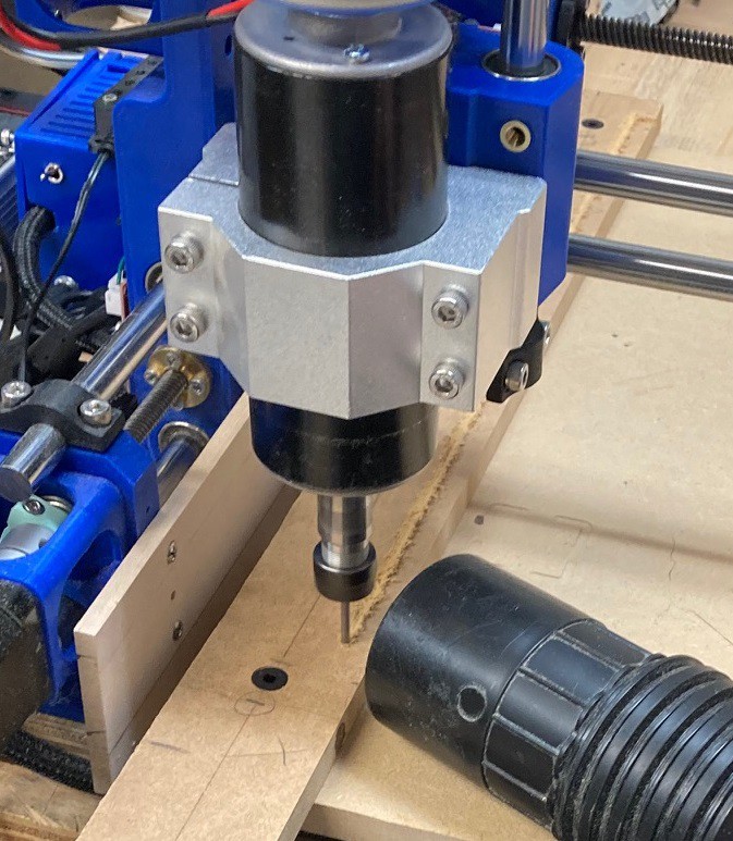
I was able to cut out a guide for my table to help when tiling cuts. I cut 3 holes in a strip of wood and then used 3D printed plugs that use a friction fit into the board and line up with the recessed holes already cut in the spoiler board for holding it to the bed.
![]()
Here I am cutting the face of the board square to the bed after taping it into place using the pins to orient the board.
![]()
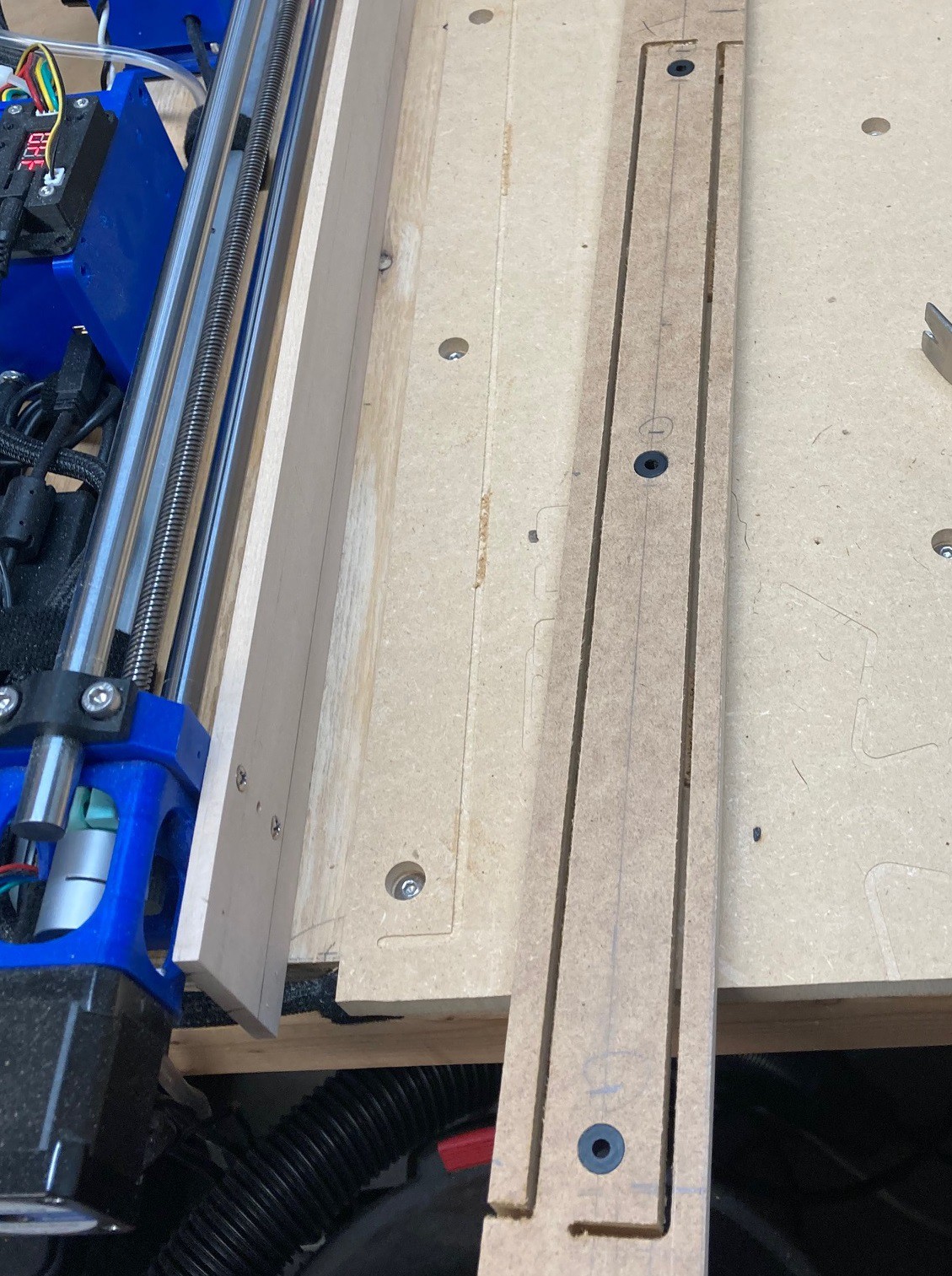
The board is wider than the cutting volume of my bit, so I flipped the board over after cutting as much as I could and then used a hand saw to cut the tab off afterword's. This has the added benefit of allowing me to install the board in either direction, giving me two straight surfaces to wear out.
![]()
It seems to be working quite well. I have not taken the time to cut my piece out, but I am all ready to do it whenever I work up the nerve.
-
Brains
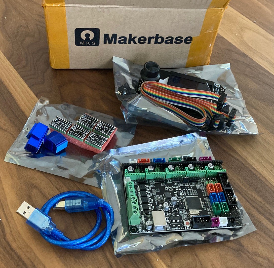
10/09/2021 at 00:10 • 0 comments![]()
So my MKS Gen L v2.1 board came in yesterday. I also picked up some Triaminic TMC2209 drivers, and a small 4 line LCD panel with rotary knob and a SD card slot. The 2209 drivers are just for fun. I was curious to experiment with sensorless homing. The LCD is not supported in GRBL but I thought I would get it to play around with Marlin or some other firmware.
As for firmware, this board is essentially the last incarnation of a RAMPS board and so it can run GRBL-Mega, however that unfortunately has not been well maintained and is not on the latest version of GRBL (it is on 1.1f and not 1.1h) and we need the latest version in order to support auto squaring of our dual y axis motors. There is a rumor that GRBL-Mega-5X supports auto squaring, although I have not been able to find any documentation on this yet. It certainly did not port it over straight from GRBL 1.1h, but may have recreated it on there own. This is in active development, so that is a plus at least.
The other board I ordered is a 32 bit board so it can't run any of these. However there are some other options worth exploring. There is GRBL-HAL that is suppose to be a more modern version of GRBL with support for lots of hardware. Unfortunately it does not seem to support any 8 bit boards, but you can't have it all. It seems to be in active development like the Mega-5x fork. There are a few other GRBL ports out there, but they seem to either focus in on one board or are not well maintained.
Moving on to Marlin you can still find 1.1.9 somewhere out there and that runs comfortably on any 8 bit arduino clone. However Marlin 2.x seems to support the Mega very well and so that is probably a better code base for starters, it also supports any 32 bit board you can think of, and has a well optimized post processor. The big win for Marlin is that it is very well supported (much better than GRBL or any of its forks), it has full support for running off of a SD card, full support for LCD displays, rotary knobs, and touch screens, and it has a very rich set of supporting software such as OctoPrint. Finally it appears to support all the things we do like about GRBL such as laser mode, auto squaring and reasonable jog support. And of course it supports 5 axis. I will need to experiment with it for a while to see if it is a seamless replacement for GRBL or if all my other tools will need to change to support it.
---
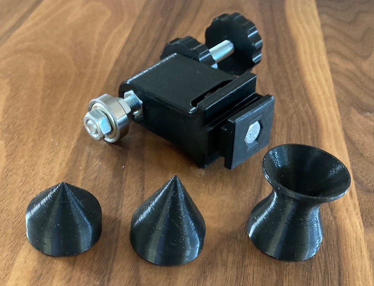
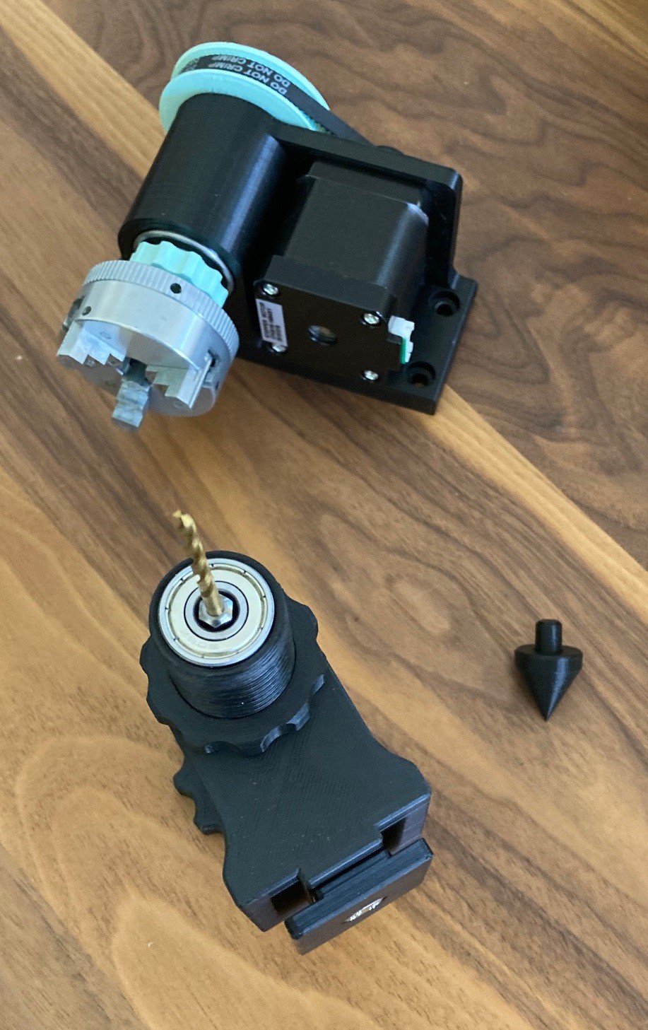
![]()
My new quill's came out great. I'm loving the idea of printing them a bit snug and heating them with a hair dryer to get a perfect fit. I don't know that the angles are right on the egg cup shaped one, but it is a start. I will need to find something round that needs machining, although honestly I had nothing in mind when I made it. It is just to prove that this idea could do more than just support pointy tips.
The bearing I'm using has a bit of play in it, and that gets translated to the quill. So far that is the only point of noticeable flex or movement in the whole system. I will need to wait till after my base board is machined to see if the foot can actually hold the whole thing stable. Maybe if that is solid I will look into buying a better quality bearing for the quill.
![]()
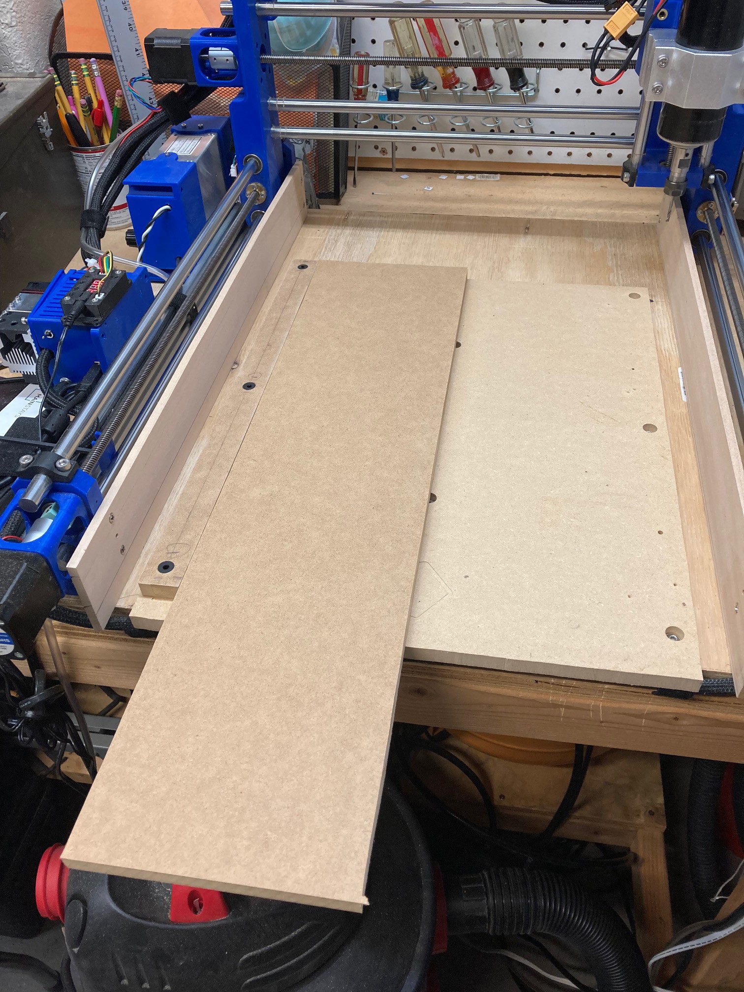
On the base side of things. I designed it larger than my working area so I will need to tile it. I thought about drilling some holes for pins and doing this up fancy but I decided to go in a different direction. Instead I'm going to make a replaceable straight edge that can be added to the left hand side of the spoiler board. Then I'm going to use the machine itself to mill that face smooth so I know it is perfectly aligned to the Y axis. That will allow me to move my piece down with precision when it is time to tile. I will need to come up with some way to mark and move it the exact right amount in the Y direction, I suspect a few pencil marks will do just fine for this, being off by a half mm in the middle of the cut is unlikely to make a big difference in the final design.
I also need to come up with a new hole pattern for my base board. I placed the hold down's for my spoiler board in a somewhat arbitrary pattern and it does not lend itself well to holding down anything but a full size sheet of wood.
-
Slide to the right
10/07/2021 at 03:26 • 0 commentsI'm still working on the final details for my rotary axis.
I have two new controllers on order. A Makerbase MKS Gen L 2.1 board that is basically a cleaned up 8 bit RAMPS board. And a Makerbase MKS Robin Nano V2 32 bit board. The Gen L should be able to run Grbl-MEGA while the robin nano can run any of the more modern 32 bit firmware. Both will give me 5 axis and should allow for the rotary axis to run without needing to disable the X axis.
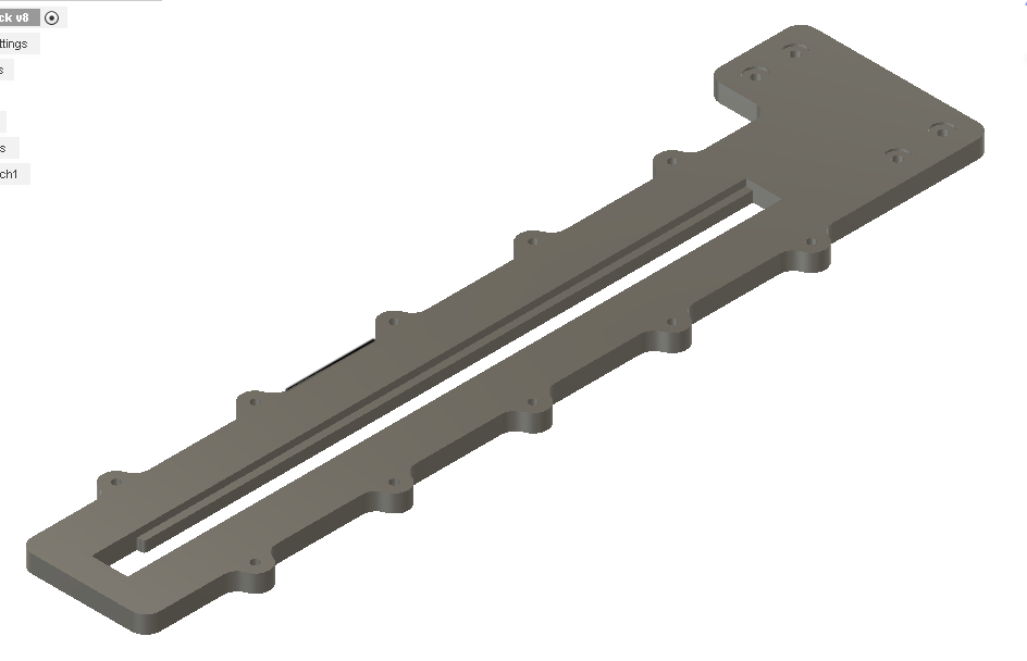
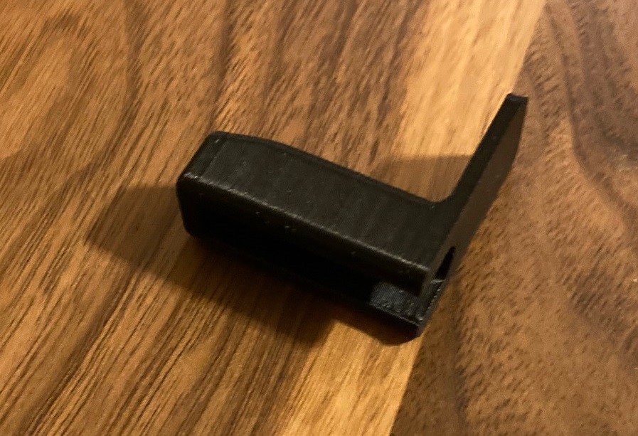
I'm also working on a base to hold everything in alignment and to allow the tailstock to quickly be slid into position. Right now this is based around a 1/2" thick piece of MDF that is 24" long (and maybe 6" wide). It is shown here up side down for machining. When flipped over the groove in the slot will allow the foot of the tailstock enough clearance to slide freely when this is secured to the base of our machine.
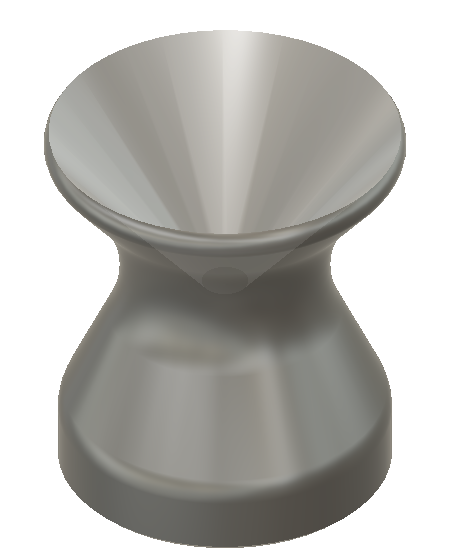
Finally I'm experimenting with new tips for the quill. This one is an inverted point that should allow you to hold the round end of an object (like an egg). I have these on the printer now, we should know how the will work out tomorrow.
-
Winner
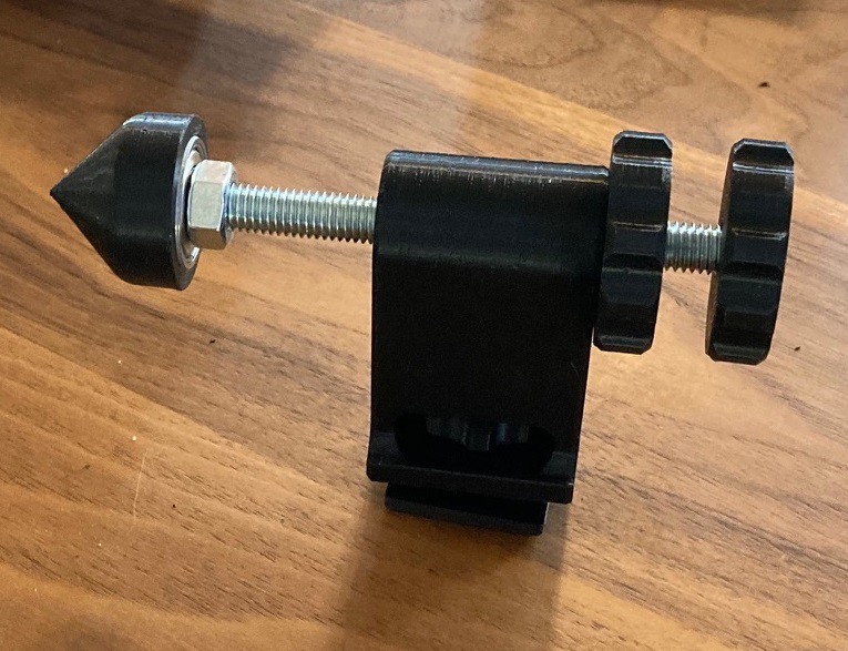
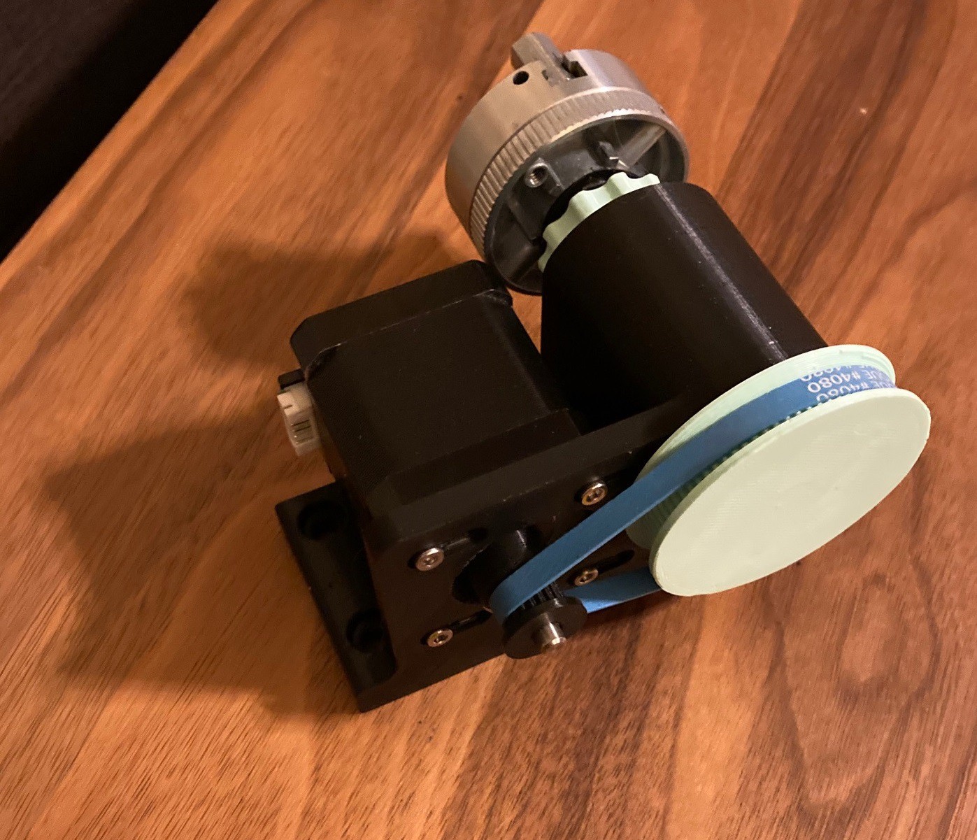
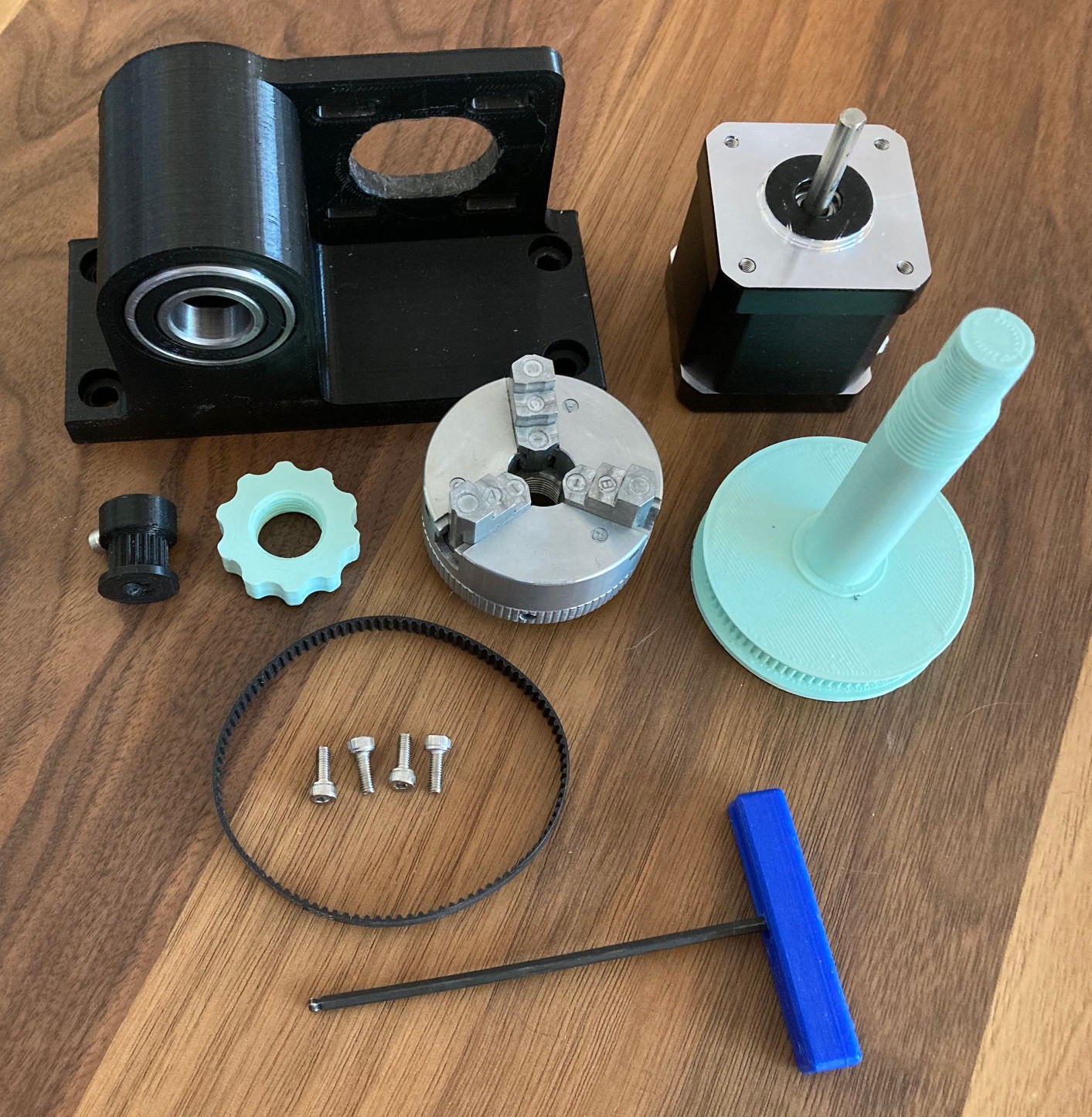
10/04/2021 at 04:09 • 0 commentsI think we have a winner here. It is a bit heavy on non printed parts, but it is solid and seems to be capable of handling a lot of side load without flexing. Anyway I need to make a base for this to slide back and forth in and make sure it all works as it should, but I think this is a nice setup.
![]()
![]()
-
Progress
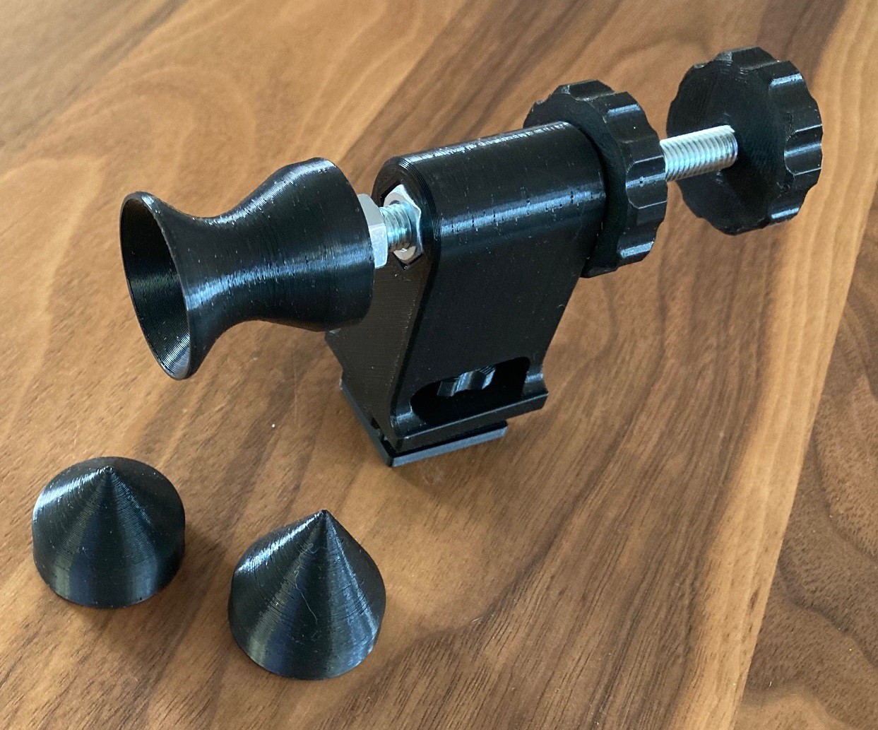
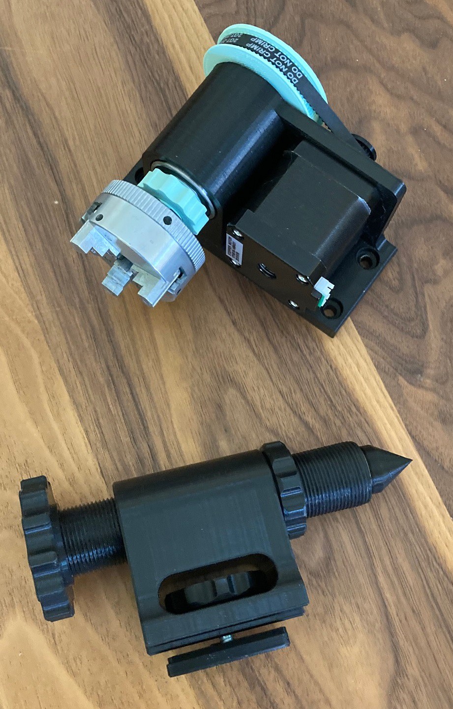
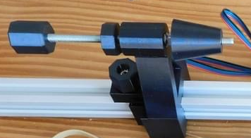
10/02/2021 at 20:18 • 0 commentsSo I have been working through some different ideas on a more streamlined tailstock. I modeled up a new tailstock in plastic that was just a slimmed down version of the previous one. It would work but I still don't like the idea of plastic threads and want to avoid them as much as possible.
![]()
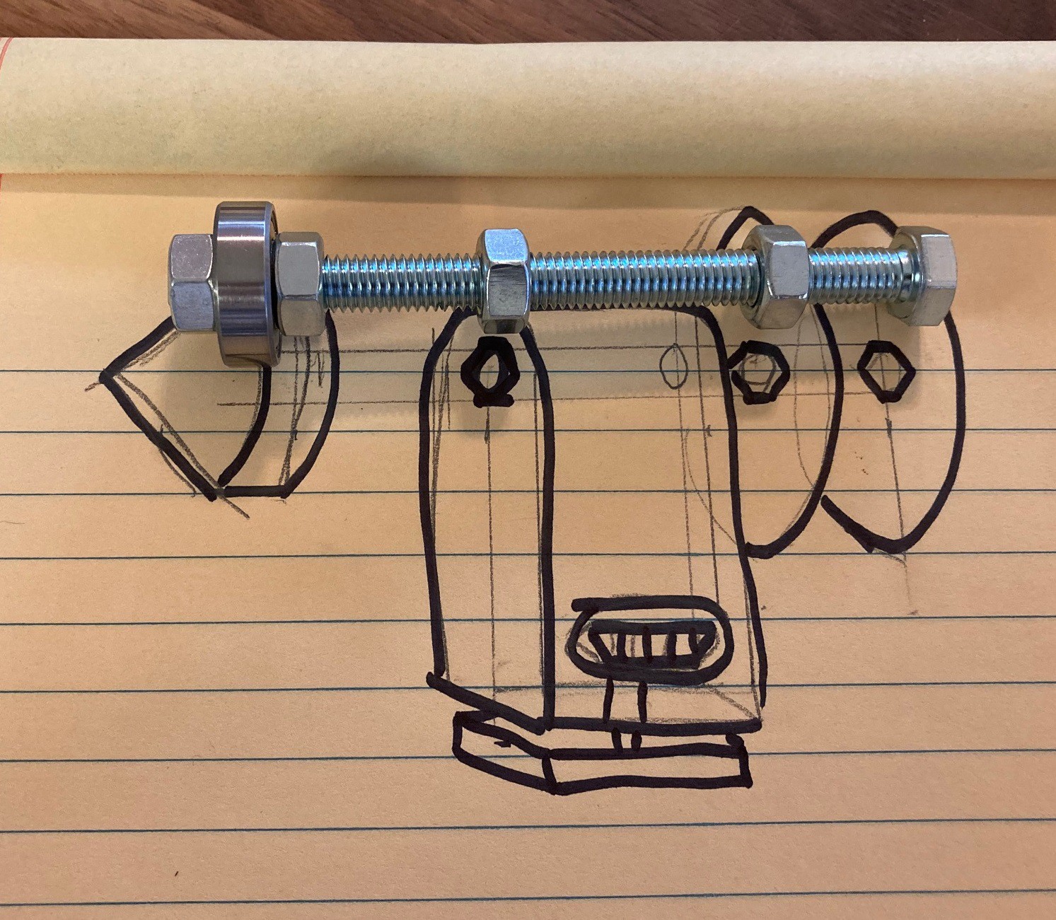
So I swung by the hardware store and picked up a 100 mm long M8 bolt and some nuts and came up with the mockup above. The idea is that we mount the end of the bolt and one nut in to some hand wheels to let us set the quill and lock it into place. Then using another nut in the base allong with a snug 3D printed bearing to act as the guide to hold the shaft stable. Finally making a captive bearing at the front to act as our quill.
The bearing at the front bugs me, it is overkill but I can't see a good way to captivate the bearing in plastic and still have a solid coupling that won't wobble around quite a bit.
![]()
Anyway a little modeling, and waiting for a print and I get the mockup you see above. I need to add a second wheel to it to lock it in place and come up with the end of the quill. I would like the quill to be modular but I don't see a good way to do that with this setup.
Maybe I need to flip things around and put the bearings in the base block and use the wheels to set the length of the rod. That way the whole rod can spin freely so the quill can just thread directly onto the rod. It is something to experiment with.
![]()
Finally as a test I took a small rubber band from a bunch of asparagus and tried that out in place of the timing belt on my 4th axis. This works, but just barely, it may be a good temporary solution while you wait on parts but I don't recommend using it this way for long. The rubber band is super springy so if you move the motor to fast you get overshoot, it also has a poor grip on the pully's. It is possible a thicker or smaller rubber band would work better, but I don't think it would be a big enough win to justify skipping buying a belt.
Now if you can't get a belt for some reason, then this may work ok for use with a laser, but never with a spindle.
-
Tailstock
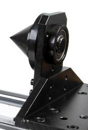
10/01/2021 at 03:14 • 0 commentsSo I needed a tailstock for my rotary axis so I can use my spindle with it. I came up with this over engineered solution that is working well but is way overkill for what my small rotary axis needs.
![]()
This is truly 3D printed with only one M6 bolt/nut and a skateboard bearing in the tip. The whole thing is very solid, all but the quill at least.
![]()
One unique idea is that there is a small (3D printed) socket hidden behind the quill so you can insert hex driver accessories in place of the quill.
The big downside here, other than just being rather large, is that the 3D printed threads are a big pain. They are fiddly to clean up and they tend to get sticky. If you lightly heat them with a hair dryer they will reform as you thread the parts together, that can help a bit. The key is lightly, only heat for a few seconds at a time, it is easy to over do things and ruin the part.
---
Anyway this would be great if you had a small wood lathe you were working on, but it needs to be slimmed down to go with my rotary axis. In particular the rotary axis does not have a whole lot of holding power and does not spin very fast.
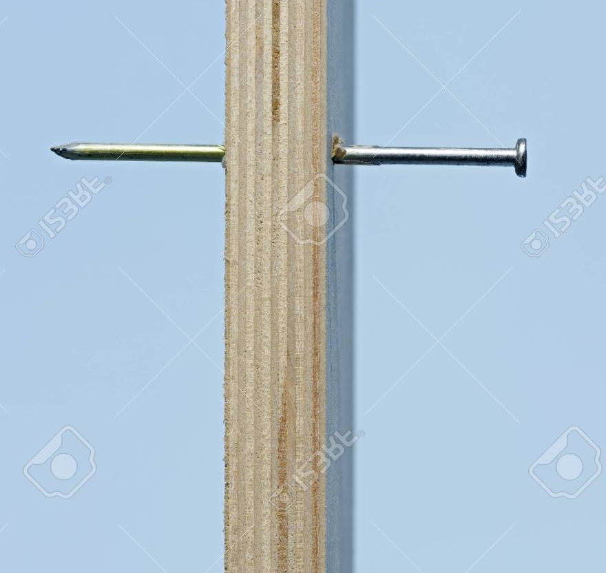
The simplest idea is to just put a nail through a board and use the tip as a rest, or any similar setup with a pin and holder. This works because our rotary axis is not rotating fast so we don't have a lot of friction. This is by far the cheapest and simplest solution. It does have three downsides however.
- The tip of the nail will wear into the material over time, causing the connection to become loose.
- Because we don't have a fine adjustment we are relying on just sliding the tailstock next to the workpiece for support. There is no way to add in any extra clamping force. That will require a deeper hole in the workpiece to make a solid connection.
- Swapping the workpiece out becomes a laborious effort without a fine adjustment, we essentially have to setup the whole operation every time, making repeat operations cumbersom.
The next idea is to add in a proper quill and bearing to the setup but not use any sort of a fine adjustment. That takes care of the first problem of wear on the end of the workpiece but nothing else. This adds only a small amount of complication, we have added a bearing and have to fabricate multiple parts, but it is still relatively minimal.The last step is to go all in and add a fine adjustment to the setup so we can apply a clamping force and quickly release the tension and swap workpieces without needing to readjust the base and risk messing up the alignment. I like the idea of using a threaded rod or bolt for this setup, I will try to find something tomorrow to act as the base. That should give me the same precision and stability as my 3D printed solution but hopefully in a smaller package.
-
Spin
09/27/2021 at 03:27 • 0 comments![]()
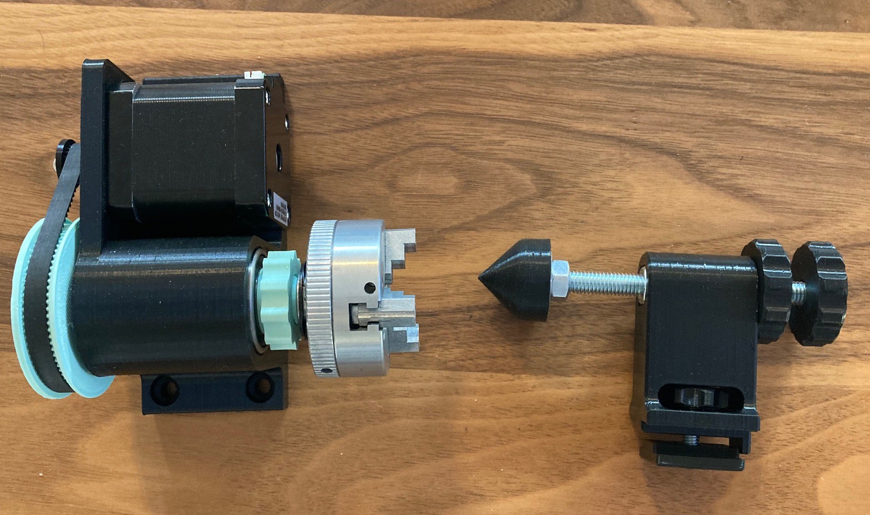
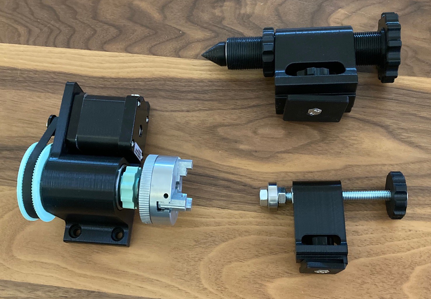
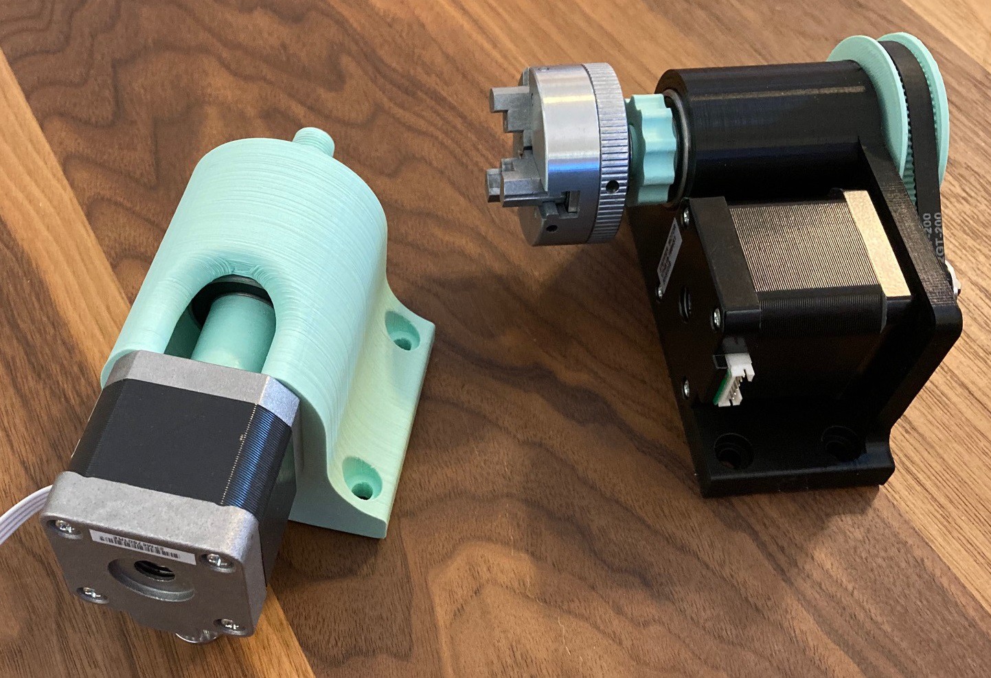
I finally took my rotary axis(s) for a spin and both of them seem to work great. The direct drive axis lacks power, I can easily stall out the motor with only a minor amount of pressure on the spindle. Coupled with its lower resolution I don't recommend using it. It does save a tiny bit on filament and does not need a belt, but the belt drive just works better.
![]()
Here is a comparison of the parts between each. It really comes down to a 200 mm belt and an extra pulley and screw.
![]()
So my system uses dual y-axis drivers with independent control during homing all running on a GRBL shield on an UNO. That leaves me with no spare drivers to run the rotary. Because there are dual Y axis and I don't want to loose z control I am swapping the rotary with the x axis for now. This works ok, but it has a few problems.
First the x axis is now just floating, that makes it nearly impossible to do any sort of milling without mechanically blocking the x axis up. It also prevents us from doing a true 4 axis mill with the x axis being free to move side to side. LightBurn can only work in rotary mode with the rotary on the y, z, or a axis, it does not support x (why I don't know, or understand). To work with LightBurn then we have to pretend the x axis is not a rotary and do all the image scaling by hand to make it wrap properly onto the material without distortion.
The math is not too hard. For my belt drive unit the stepper motor has 200 steps per revolution, with the 3:1 gear reduction that goes up to 600 steps/revolution and with 1/16 micro stepping enabled that goes up to 9,600 steps per revolution, or 26.67 steps per degree. My x axis was already setup to 400 steps per mm, so doing a bit of math we get 24 mm of x axis motion in LightBurn equal to one revolution.
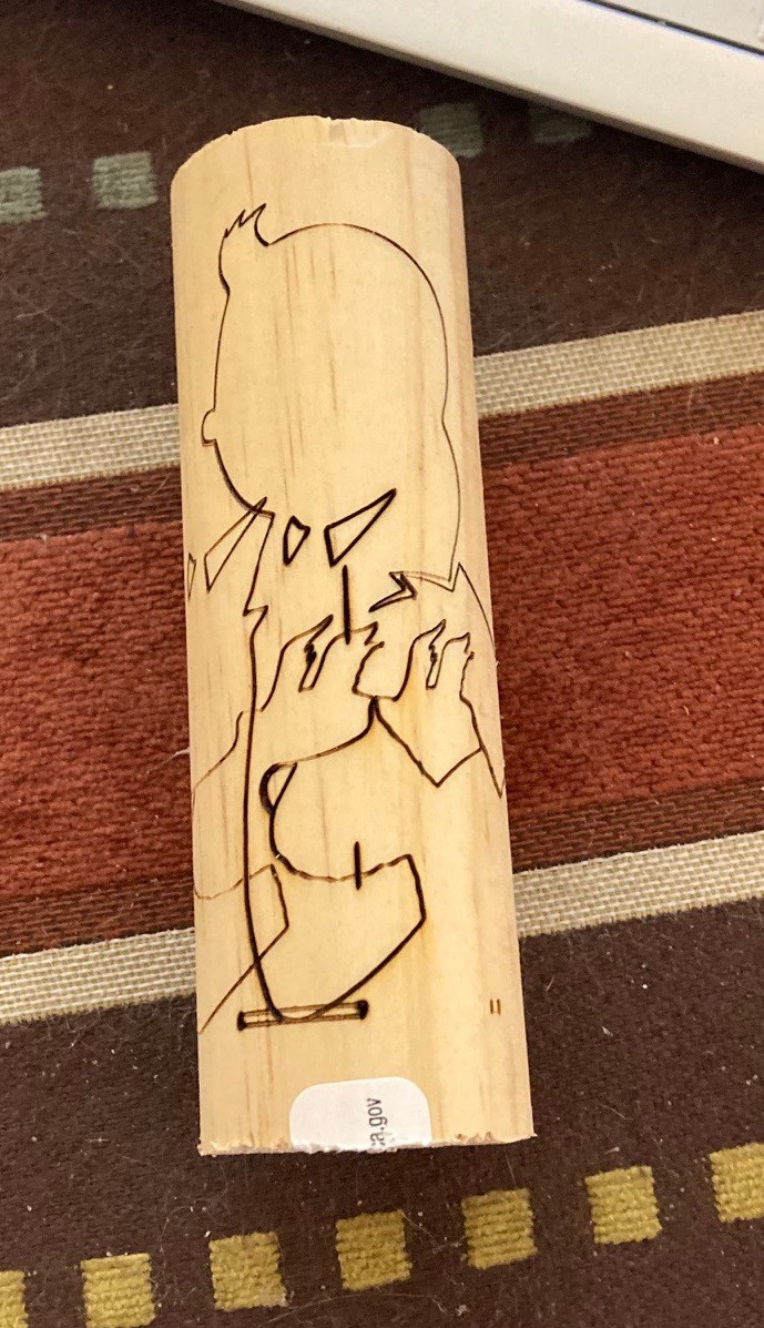
In order to make sure the image on our cylinder does not end up with any distortion we have to do a bit of math and rescale the x axis of the image. In my case I have a 31.8 mm diameter dowel, multiplying by 3.14 gives me a circumference of 100 mm. Since 1 revolution equals 24 mm on our controller we then need to rescale all our images by 0.24 (24%) in the x direction.
In your editing program you would then create an image 100 mm wide and however tall you want the pattern to be. Once you import it into LightBurn you would rescale the x axis by 24%, being sure to unlock the x and y axis so we don't rescale the whole image.
![]()
It is a bit hard to tell here, because I burned over the same spot more than once on previous tries, but the left facing tin-tin is scaled properly. My focus was set a bit high because the base of the laser was interfering with the rotary chuck. That has made the non square nature of this laser even more easy to see. I suspect the small diameter of the stock also played a role, and it is possible that I did not have my laser focused exactly over the center of the axis of rotation.
The big question is, is this worth while? I think as long as there are not enough axis available on the controller this becomes a difficult thing to recommend. There is just too much math involved and it is too tricky to make it all work. I have a few 5 axis controllers on order and we will see how they work once they get here from China. In the meantime I will keep experimenting, but I hope it works out well in the end once it can be built more permanently into the machine.
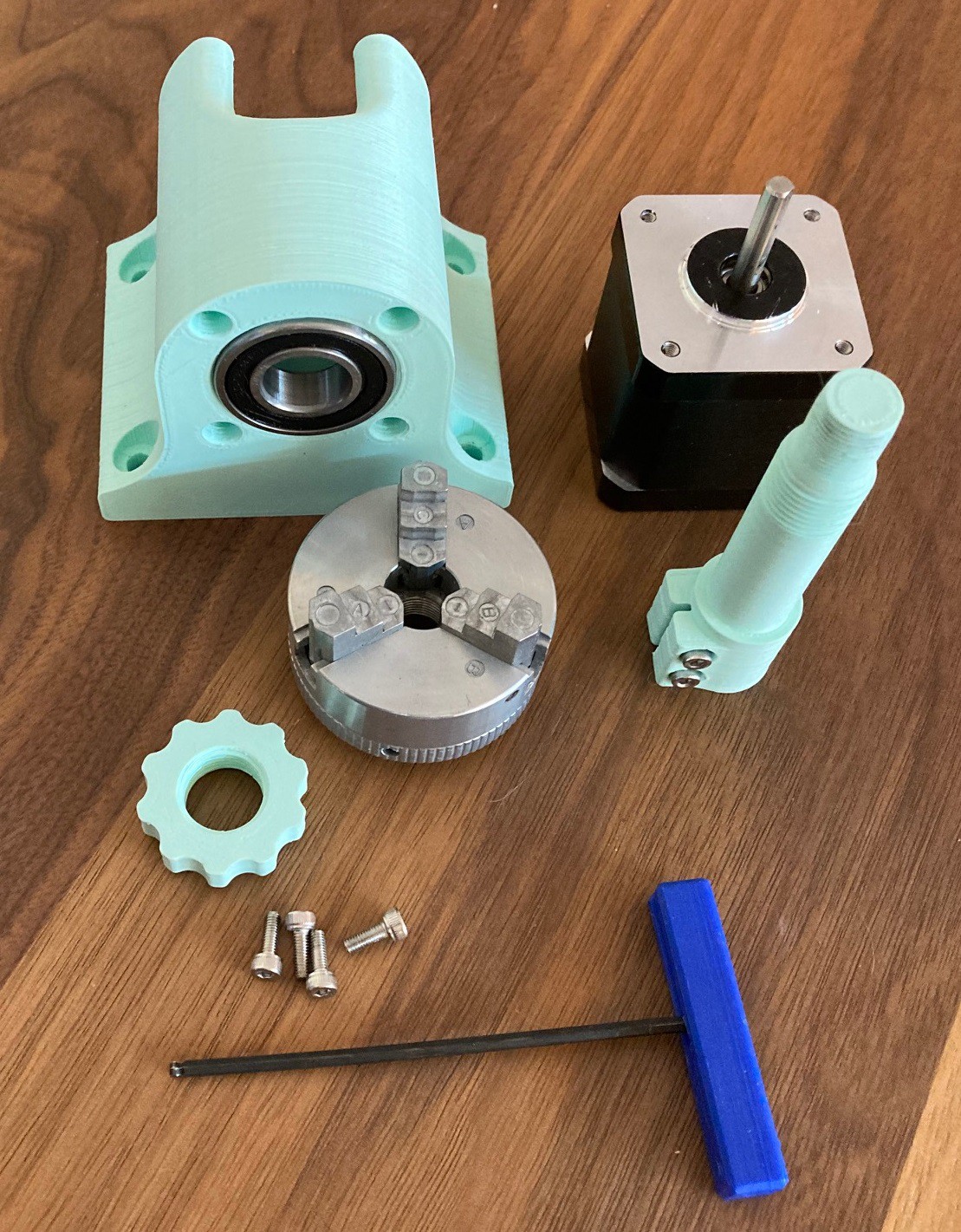
I still need to come up with some way to support the other end of the workpiece, probably with some sort of a live center. And I would really like to get rid of the 2" metal chuck and go with an all 3D printed chuck, and/or other adapters that can be easily swapped out. I would keep this chuck but it relies on a very fine pitch thread that is not really a good fit for any future chucks, I would much rather rely on a more robust thread or some other hold down mechanism.
Also the bearings I'm using have a lot of resistance, and that is made much worse when I tighten the nut on the shaft down snug. I need to put some sort of a standoff between the bearings that I can tighten everything down against, and ideally I would clean out the bearings as well, they feel like they are packed with grease and that is probably cutting down on some of my stepper motor torque.
---
I put up plans for my belt drive rotary on thingiverse.
-
Carvera
09/26/2021 at 20:39 • 0 commentsI have been closely watching the progress on the Carvera Kickstarter campaign. It is an intriguing machine. Basically everything my machine can do it can do, but with the opposite level of quality and cost. My machine is very low cost, at around $400 while there's is more like $4,000 (after kickstarter is finished). On the other hand theirs is fully finished and has a pile of features I could not hope to replicate.
They have a proper 4th axis and a laser built in, along with a full enclosure with integrated dust collection. Most importantly they have a fully automated tool changer, with probe, and solid electronics that handle all reconfigurations of the machine seamlessly without needing to know any electronics.
I'm especially intrigued by there PCB fab that can make solder masks and do via's, giving you production quality boards in a few hours rather than sending work out to a fab.
I also like there idea of using a sacrificial spoiler board that fits under your material and then using top mounted clamps to keep it all in place. That is an intriguing way to work through the thorny issue of how to integrate clamping in your spoiler board without damaging the fixtures as you cut.
Probably the most interesting part of this machine (and machines like it) is the idea that it could bring CNC out of the garage and into the home and make it safe and convenient enough to be used every day just like a 3D printer. I feel that both 3D printing and CNC has a real place in the home, but we need to come a long way still on each to make them simple enough to use that most users can work with them without specialized training. 3D printers have made some improvements but this is one of the first major moves on the CNC side that I have seen. I would consider it as significant as a Cricut or Glowforge in there respective markets. We will see if this machine (or some other) can make that jump from CNC enthusiasts to regular old makers.
Teaching Tech did a good review of the machine. You can see some issues that still need to be worked out. They need to deal with some screws coming loose, better feet that don't scuff, a laser safe shield on the front, and some way to deal with dust that falls through the bottom of the machine. However those are all pre-production issues that could be sorted out quickly.
I don't have $4,000 to invest in this machine and I don't have the space for it, but if I did I would be tempted. To be clear this is all based on one review and online specs, the machine itself could be amazing or a complete dud, do your homework and don't just go by my enthusiasm.
You can see more on the campaign on there kickstarter page.
-
Dust-Up
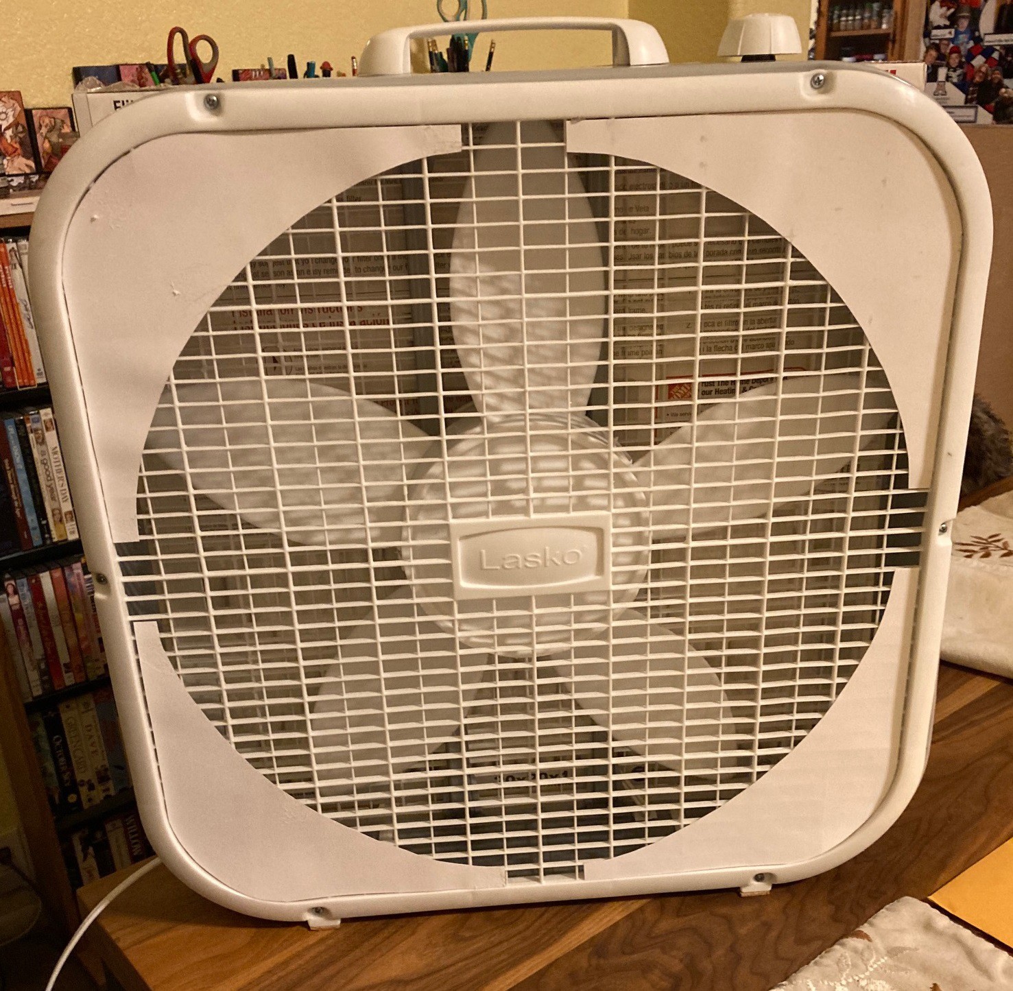
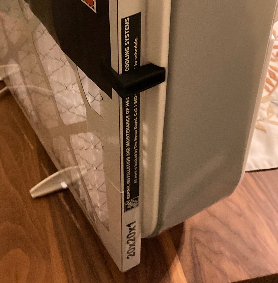
09/26/2021 at 04:07 • 0 commentsSo it was time to upgrade my smoke filter. Previously I had just taped a 20"x20"x1" merv13 filter to a $20 box fan. That was working ok but I wanted to see if I could make it perform better.
![]()
From my last post I worked out what size baffles to make. After spending a bit of time with the scissors I came up with baffles that just fit inside the frame so they could sit flush against the grill. To attach the baffles i experimented with various glues and tape but ended up removing the grill and hot melt gluing them from the back. You want the baffles on the outside of the grill so the suction pulls them tight against the grill. That makes it so you don't need a very secure mount since the air pressure does all the work.
![]()
![]()
To make it easier to maintain the filter I printed some small brackets that can be attached to the face of the fan to hold the filter in place. Again the air is pulling the filter tight against the fan so no need for this to be overly complicated.
![]()
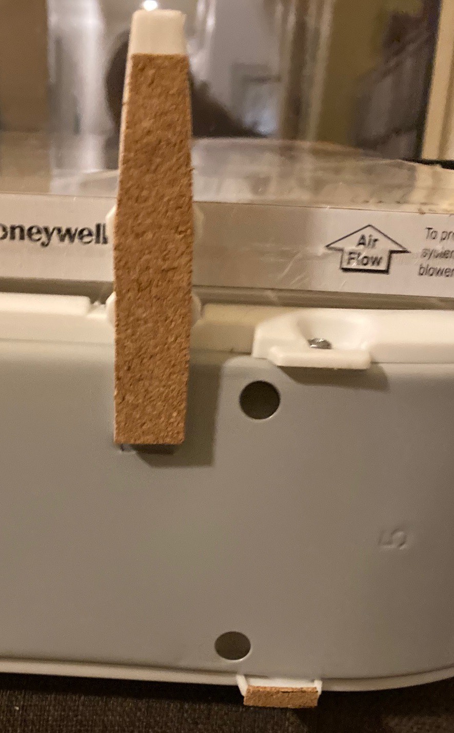
Since I had some cork laying about I went ahead and added it to the feet. That seems to have stopped the fan from rattling around when it was running.
I also wanted to see how much air flow was lost with the filter in place. Measuring near the center of the blade (not the center of the fan) I was getting 6 m/s of air without a filter and 4.3 m/s with the filter. That is a loss of about 20%.
---
I'm using a Lasko 20" box fan, the cheapest model I could find. It looks to be rated for 1820 CFM and rated at about 50 watt's for the motor.
They make a more powerful model for $30 that has a 100 watt motor and claims 2000 CFM. For twice the power they are not getting much more air flow, I suspect the problem is my model is overstating its CFM.
And an even more powerful model for $77 that has a 130 watt motor and claims 3460 CFM. That is almost twice the CFM of my fan.
-
Dust in the wind
09/25/2021 at 18:25 • 0 commentsSo I have wanted to investigate adding a baffle to my smoke exhaust fan for a while now, and I finally found the time for it. My fan has a 20" blade, so in theory moving out from the center of the fan we should see air blowing out from 0" to 10", and the idea is that past 10" the air actually gets sucked backwards through the fan.
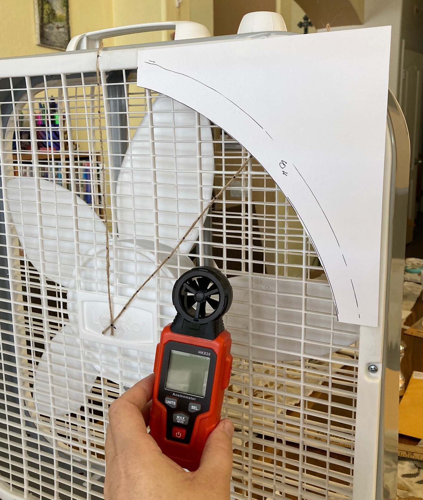
To measure this I picked up a cheap handheld anemometer from Amazon for $6. This works well with a few exceptions. For one it reads out bogus values when the fan is not moving. It also does not have a direction indicator on it to tell you what way the air is moving, so you have to watch the fan carefully and not just look at the display.
![]()
To take measurements I secured two pieces of string to the fan, one going vertical and one at a 45 degree angle along the diagonal. Then using a yard stick I marked out radiuses from 0" to 13" on both strings so I had a reference for measurements that would not interfere too much with the air flow.
Measurements were take with my anemometer in m/s with the center of the fan located over the center of the mark on the string and the back of the anemometer flush with the fan grill.
For a baffle I cut out a 9" diameter circle from a piece of cardstock and cut it square. Then when measuring air flow with the baffle in place I simply taped it to the edge with two pieces of scotch tape, lining it up on my 9" mark on my string. This is held in place by the reverse flow of air from the edge of the fan, you don't need to worry about it blowing away.
![]()
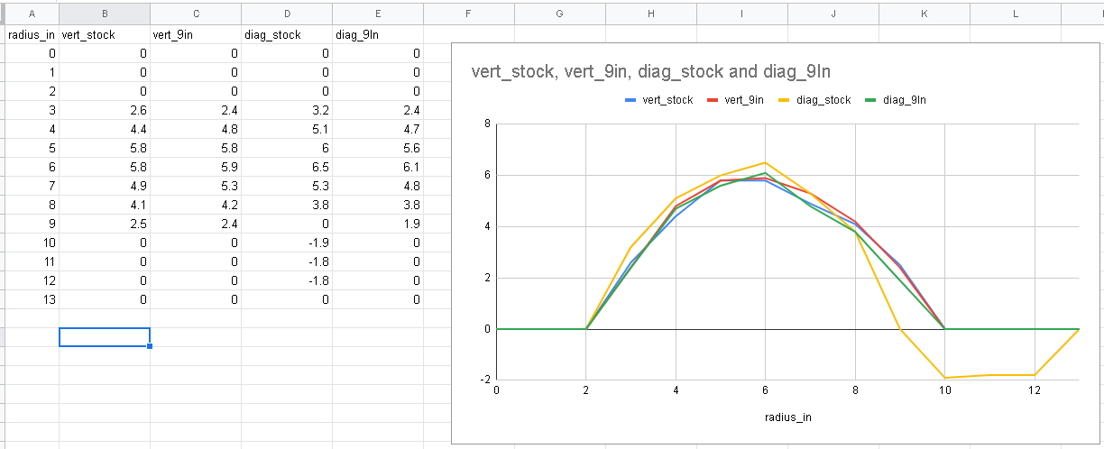
Enough talk, time for some data. Here are the air speeds across each profile with and without the baffle in place. You can see that the vertical and diagonal profiles are almost identical except in the corner without the baffle. In that case at 9" the air comes to a stand still and after that it starts blowing backwards through the fan.
The area under the curve shows us how inefficient these corners are. If we removed the box from the fan I predict that we would loose 30%-40% of the air to this reverse effect, so the box is critical. The baffle is not as important because the surface air of these corners is small. Given the area of our box is 20*20 = 400 square inches, and the are of the positive air flow is 3.14*10*10 = 314 square inches, then the area with inversion is only 20%, and if our losses on that are are 30% then the total loss is only 6%. That is an under estimate, since the inner portion of the fan is not moving any air, but that is a relatively small surface area. And of course I'm just eyeballing the losses in the corner, it could be greater or less than 30%.
Anyway I need to decide if I'm going to get fancy here, or just tape a few pieces of cardstock to the corners. But in any event there is some benefit to adding a baffle.
Also I measured the air flow out past the edge of the housing, there was no measurable air movement so the box was effectively stopping air from being recirculated from the rear back to the front of the fan. Finally I moved my baffle out to the 10" mark, right at the very tip of the blade, and at that point I still got some air inversion so the baffle was not fully doing its job. There is a reason to make the baffle smaller than the blade of the fan.
MultiBot CNC v2
A low cost 3D printed CNC that can be built with minimal tools yet is capable of great things.