David Tucker
-
Clamp
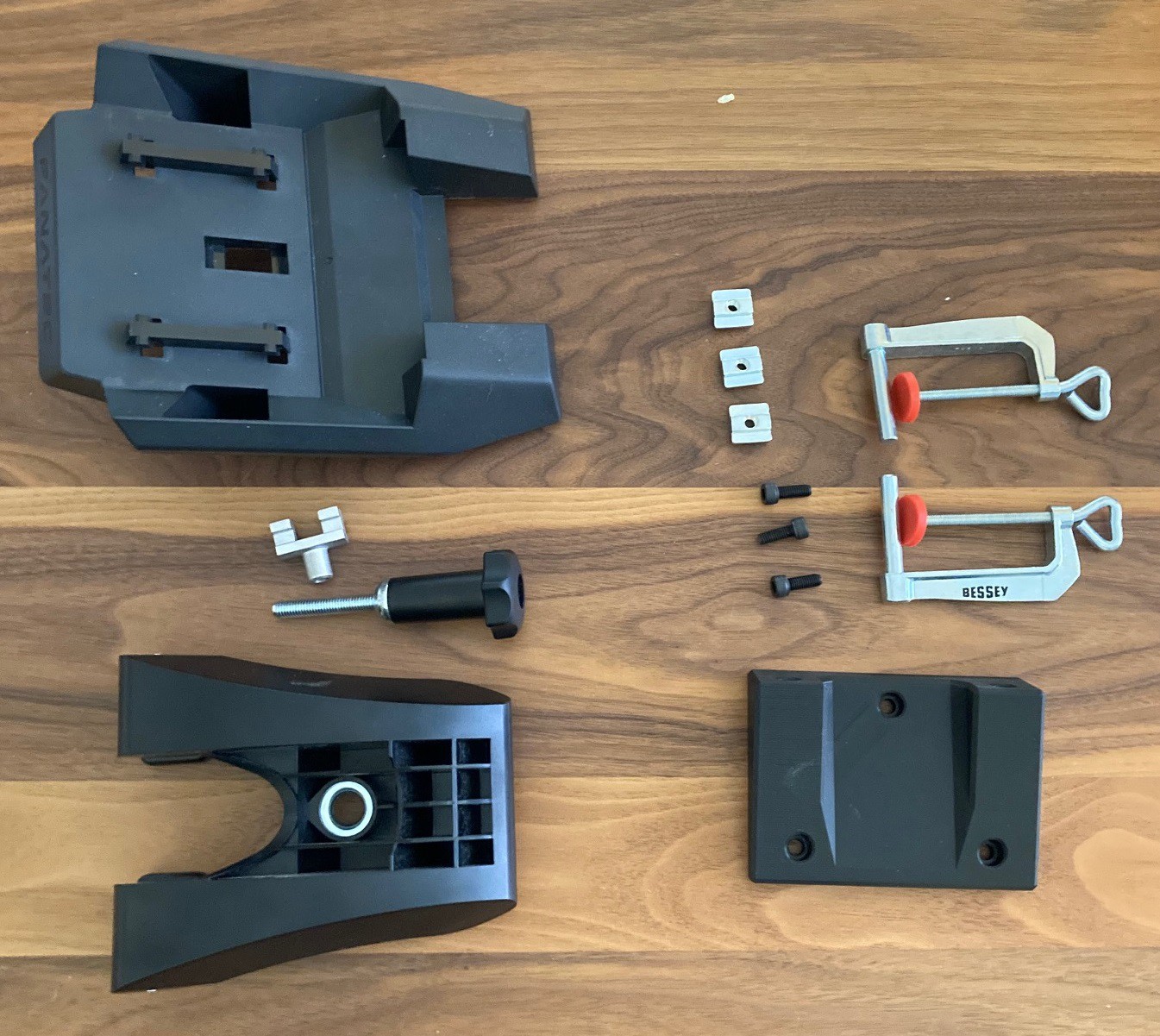
09/25/2021 at 03:36 • 0 commentsNot really CNC related, but I made a table clamp for a Fanatec CSL DD wheel to replace the overly complex clamp that Fanatec provides. The Fanatec clamp is on the left and mine is on the right. The Fanatec clamp leaves the wheel hanging most of the way off the table and that makes it have a lot of flex.
![]()
-
As the gear turns
09/19/2021 at 03:38 • 0 commentsEdit, fixed some bugs with the equations.
---
For my rotary project I needed to 3D print a gear that would interface with a toothed timing belt. However when I tried to wing it and make one without doing any real research the belt did not interface with the gear very well. After doing some research online I came across this guide that provided some good inspiration.
![]()
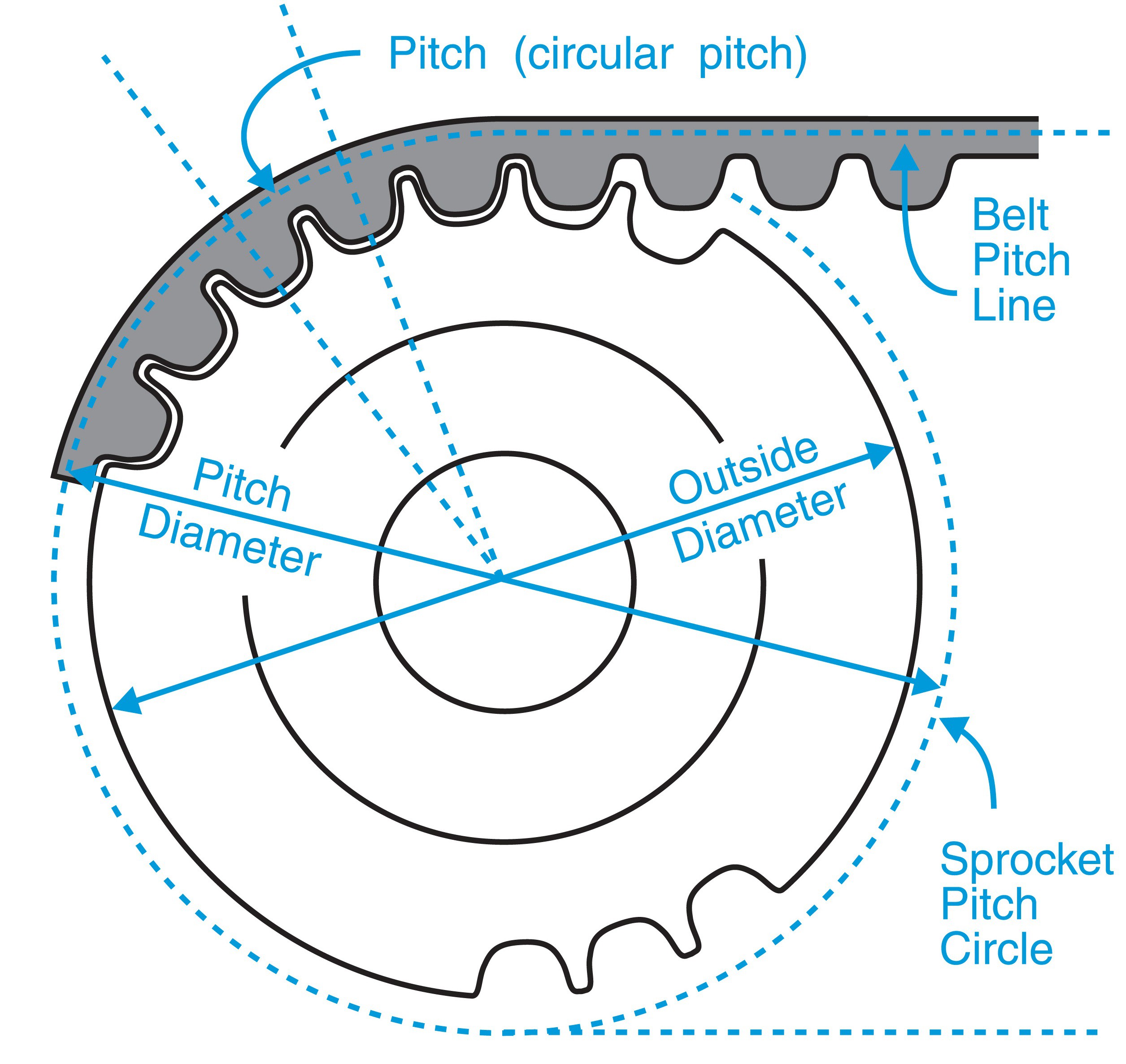
On the face of it this appears very simple. I have a belt with 2 mm spacing on the teeth, I'm looking to make a pully with 20 teeth so I need it to have a circumference of 40 mm. Using a handy circumference calculator online I worked out that my gear has a diameter of 12.732 mm.
However that is an overly simple view of the process. The above is true, but the belt itself will be wrapped around our gear, and in the process it will stretch a bit on one side and be compressed a bit on the other. It turns out the line where the belt neither stretches or compresses is half way through the belt itself (no including the teeth).
![]()
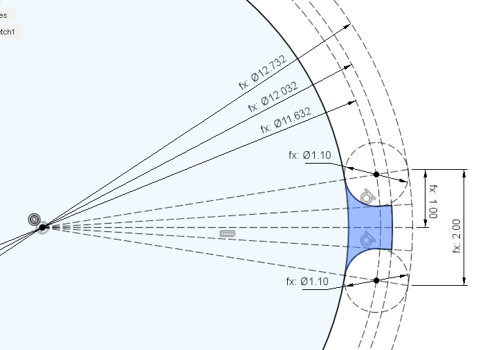
Given a diameter for our gear (12.732 mm), we subtract the width of the belt (1/2 width on each side of the diameter) to find the outer face of the gear (12.732 mm - 0.7 mm = 12.032 mm). The teeth on the belt are made of half circles that are 1 mm in diameter. To add a bit of clearance I added 0.1 mm of padding around each tooth, that should cover any inaccuracy's in the printing process. The height of the tooth is 0.7 mm, just a bit more than the 0.5 mm if the tooth would form a perfect sphere.
![]()
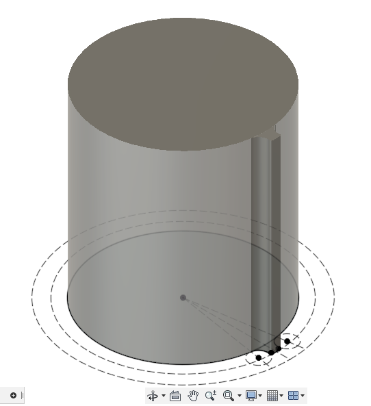
Once you have your tooth designed then extrude the body of the gear and the one tooth as a separate body. Add a small bevel to the edge of the tooth to make it move in and out of engagement with the belt smoothly.
My belt is 6 mm wide, so I made my gear 7 mm wide plus 2 mm on either side for the edge that holds the belt onto the gear.
![]()
Next we select our new tooth and replicate it 20 times, remember to select it as a body ad not as a face. Finally use the merge tool to combine all the teeth together with our gear body. This is less cumbersome then trying to replicate the tooth in our original drawing.
![]()
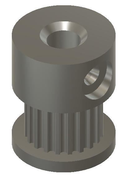
Once we have the teeth modeled then we can go ahead and polish it all up with a lip on either side to retain the belt, a hole in the center to fit our stepper shaft, and a hole to allow for an m3 bolt to lock it onto our shaft. Notice that I beveled the upper flange at a 30 degree angle (give or take) so that this can be printed in place. It may have been better to invert the design so the taller flange is flat on the bed, that would minimize the chance of failure if the bevel was not sufficient.
If you need to calculate the (approximate) spacing between two gears, given a known length of belt, then use this handy belt length calculator in reverse. Keep in mind that this is based on the center of the belt and not the diameter of the gear.
![]()
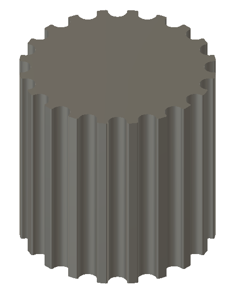
If we did our job right we end up with a perfect facsimile of a cast metal gear.
-
Old Ghosts
09/19/2021 at 02:02 • 0 comments![]()
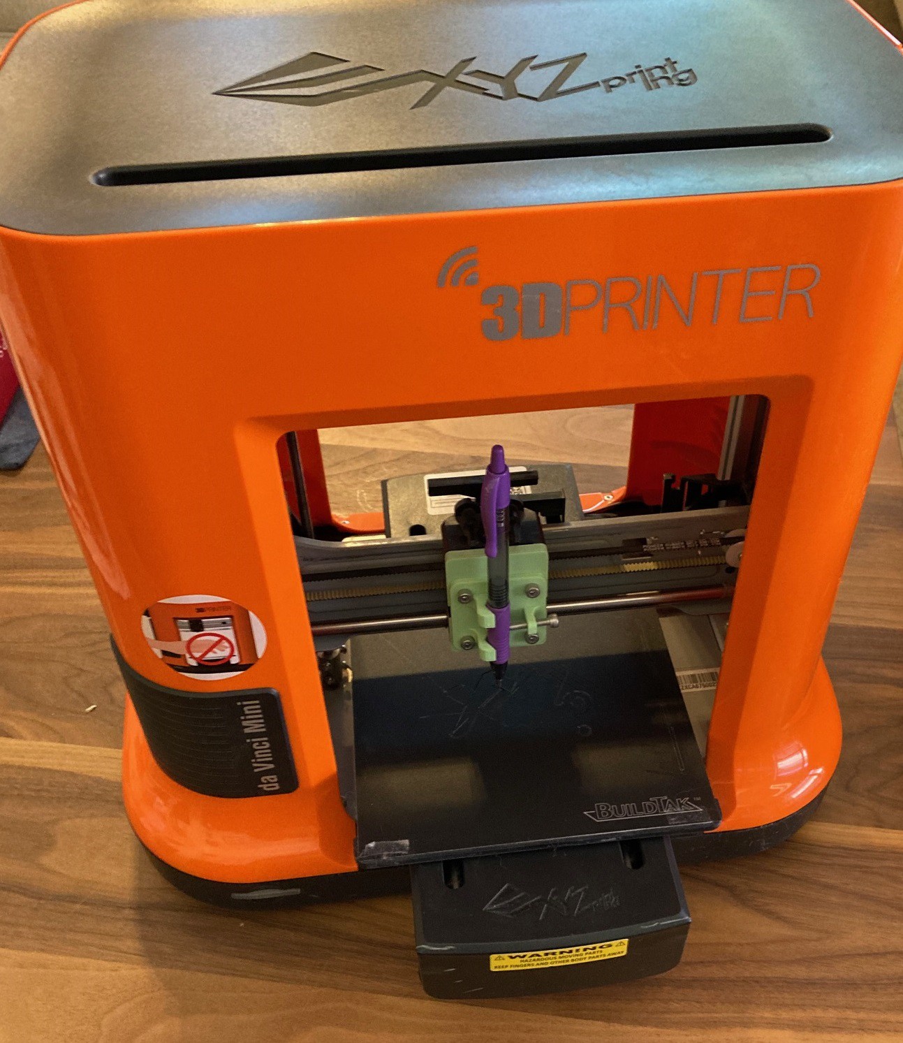
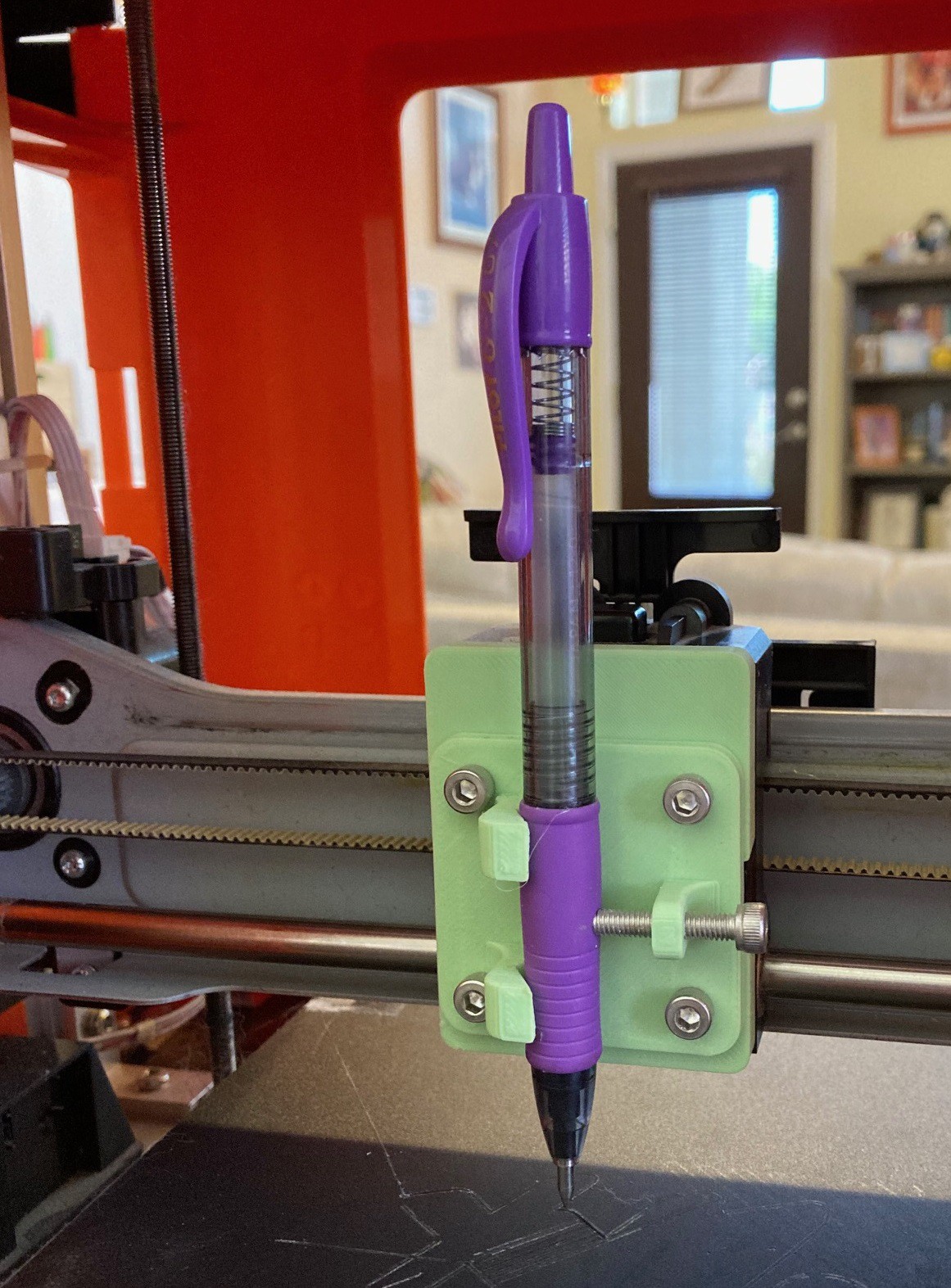
Here is an old cnc project I made when I was just getting started with all of this. I had a broken XYZ DaVinci Mini W printer that was missing several key parts. I decided to turn it into a pen plotter.
![]()
I made a new pen holding tool head that fit with the built in quick release of the original head. To make the pen have some give to it for a more natural line I took my pen apart and moved the retract spring from the bottom of the pen to the top so it provides some downward pressure and has a quarter inch of give.
![]()
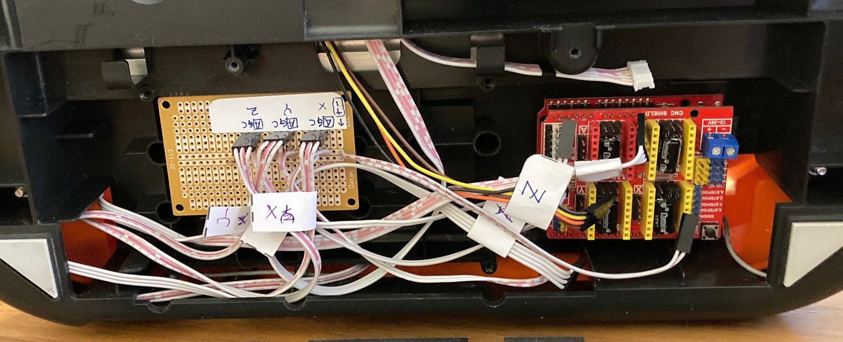
On the control side I removed the original board and replaced it with a grbl shield and an uno. I made a small daughter board that lets me use the optical limit switches already built into the machine. I don't remember the details anymore but I had to wire in some sort of a transistor to make this work.
Anyway it worked fine for what it was, and it was a good way to get some CNC building experience before setting out to make my MultiBot. I have no idea what I will do with this but I thought you may be interested in a bit of the history behind this project.
-
Wired for speed
09/18/2021 at 22:37 • 0 commentsI never did make a proper post on how to setup a grbl shield. I don't know that this one will be proper either, but hopefully it helps out a bit.
![]()
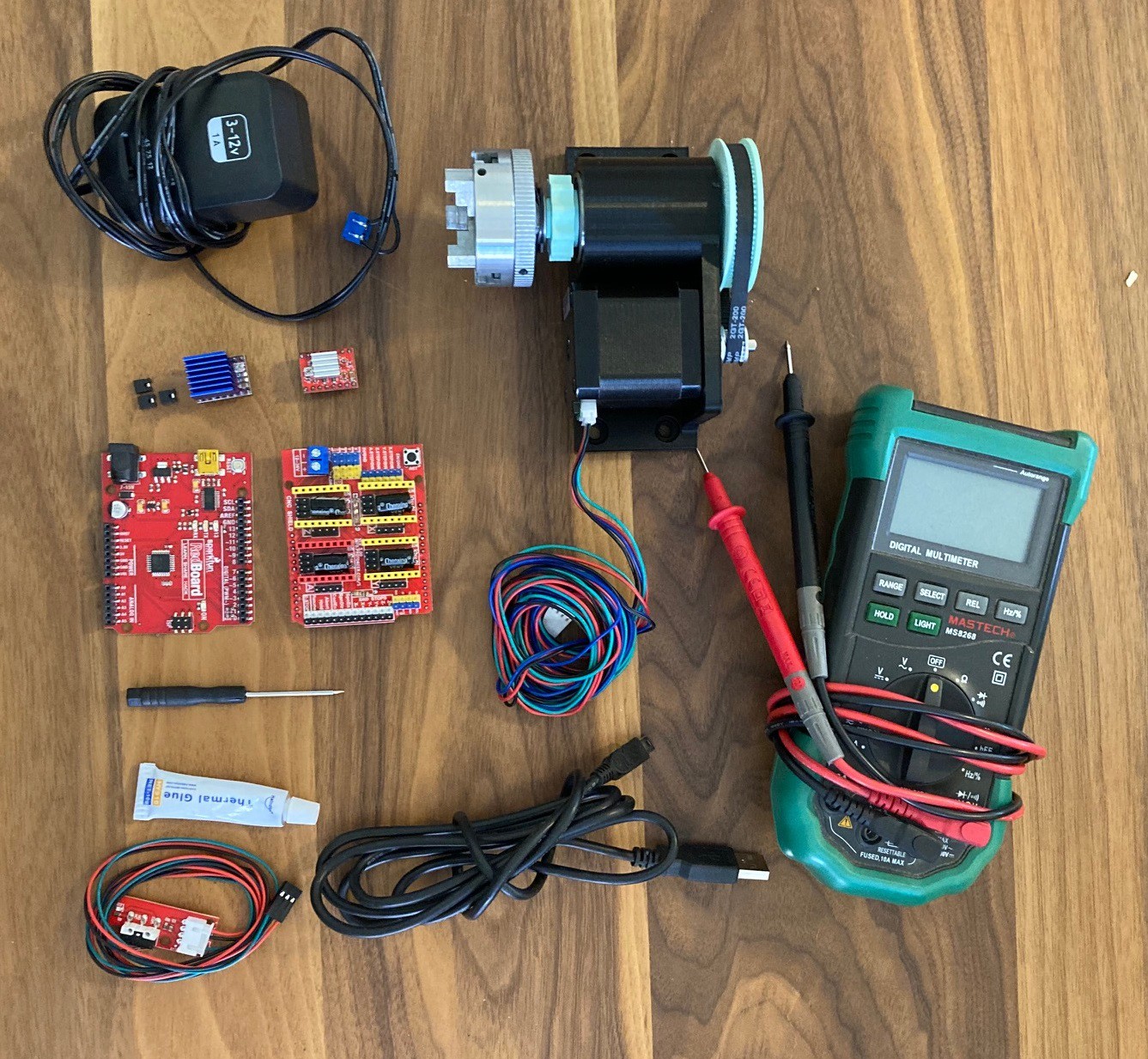
To get grbl running you need an arduino uno, a grbl shield to make connecting all the wires simpler, a stepper motor driver, a stepper motor (of course), a 12-36v power supply with enough amps to drive all your stepper motors (24v 3amps is a good minimum) and optionally some limit switches.
In addition you will need access to a volt meter and a small screwdriver for setting the reference voltage on the drivers. And if you don't want the heatsinks to fall off then some thermal glue to glue them down with.
![]()
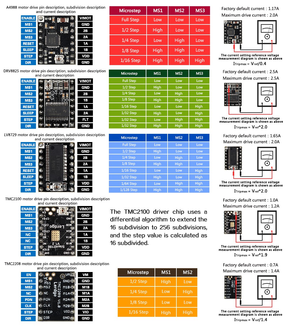
There are several different stepper motor drivers you can get. I won't go into all the details of them but if you want a quiet driver then look at the TMC2208 or higher, if cost is a factor then look at the A4988.
Modern drivers can run with different amounts of micro stepping. This is where the driver carefully mixes the current goin to each coil to hold the motor partway between poles to increase the step resolution and to smooth out the motion. I tend to run my stepper motors at 1/16 steps, this is a nice compromise between too rough and too many steps.
The above chart can be used to work out how best to setup the jumpers for micro stepping, in addition it shows you the preferred orientation of the board. If you get confused look for the enable pin on the board and cnc shield and make sure they line up properly.
![]()
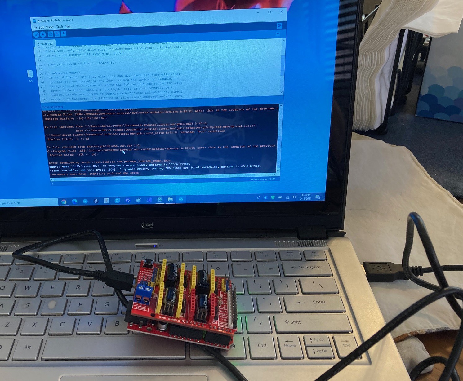
The first step once you have all your parts is to download grbl and install it. I won't go into all the details, but basically you install the Arduino ide, unzip the grbl package, and compile the grblUploader project to send it to your Arduino uno. I recommend you do this before attaching the grbl shield to your Arduino, this way your not fighting with any issues the shield may have when trying to install grbl.
![]()
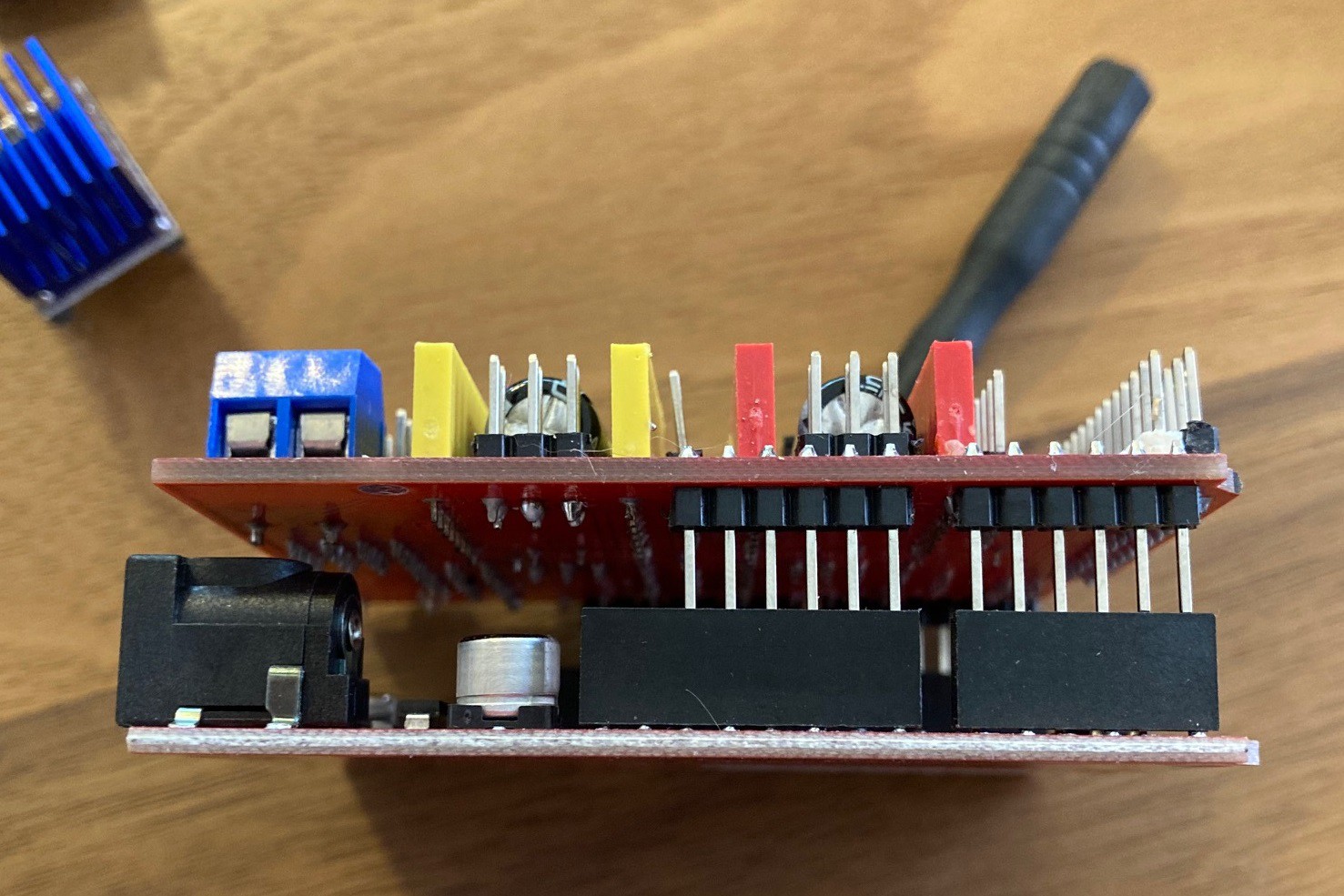
Next we can attach the shield to the Arduino. Unless your Uno is really old you will find it has more spaces for pins than the grbl shield. Look for the gaps between the pins to make sure you are lining it all up correctly.
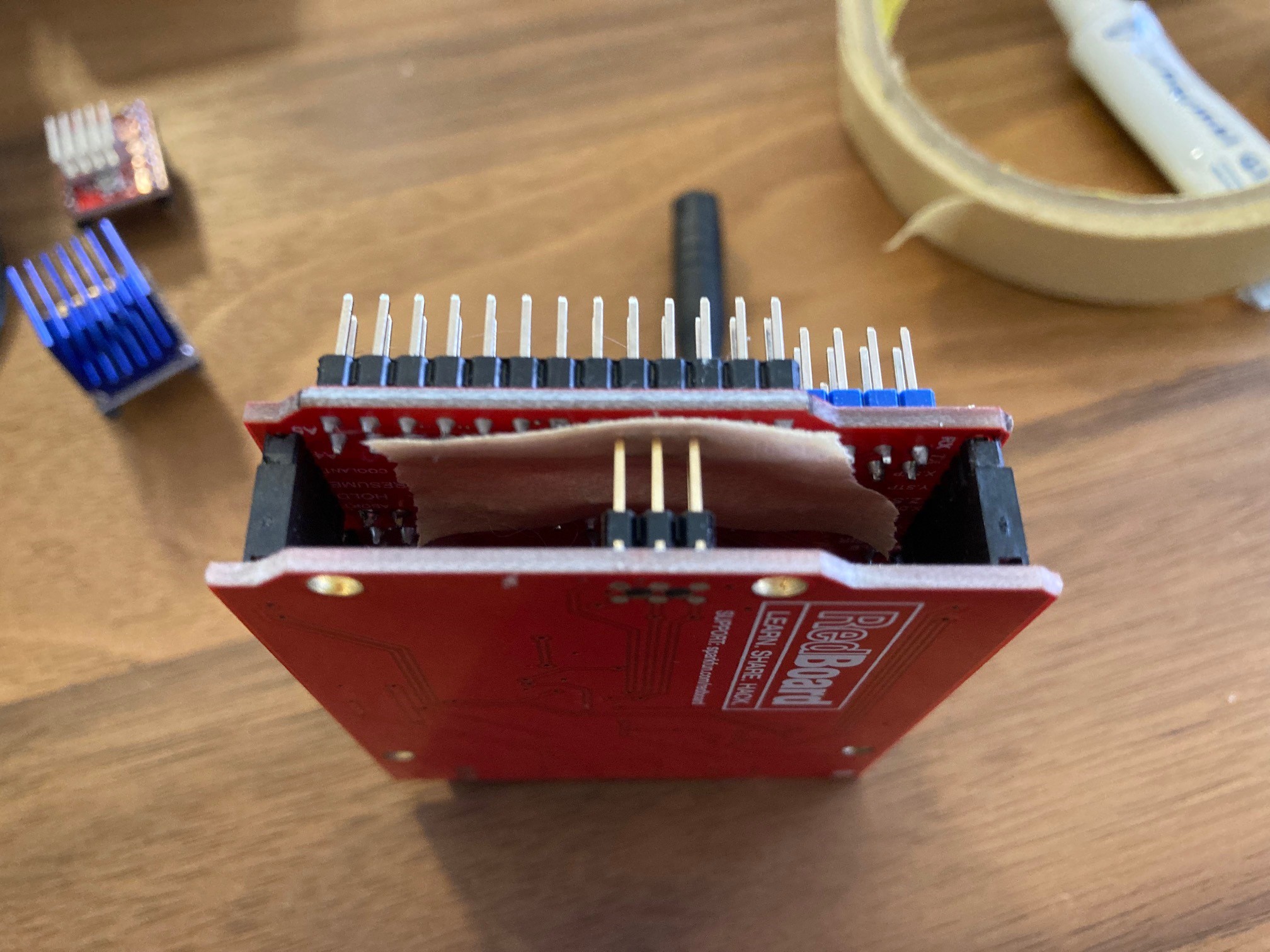
![]()
Some boards have extra SPI header pins on them that can come into contact with the bottom of the grbl shield. A piece of tape can help keep the pins from shorting out. Also watch the USB plug on older uno boards that have a full sized usb jack.
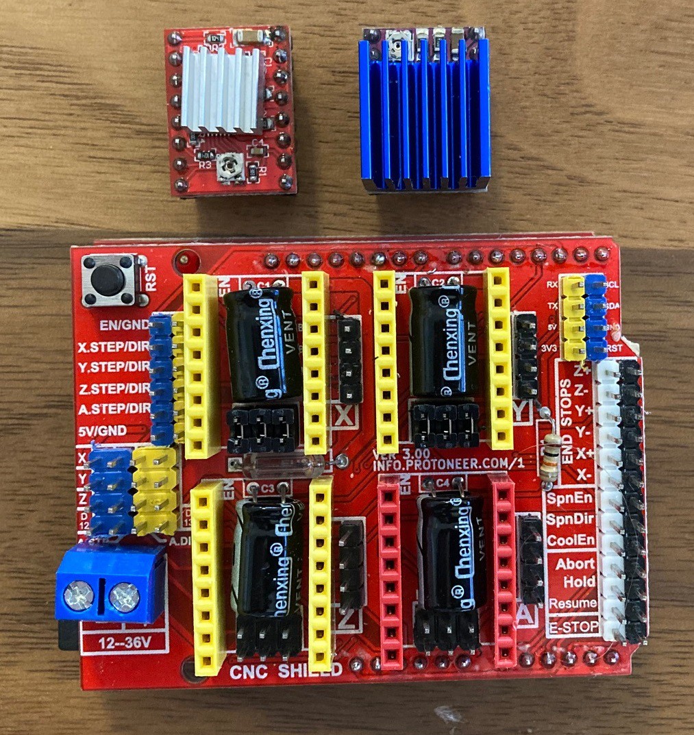
![]()
Following the diagram above, set the jumpers between the yellow headers to match your microstepping. Sown here are the proper jumpers and driver orientation for both a A4988 (left) and DRV8825 (right) driver. Go ahead and plug in the drivers in the appropriate slots (usually x/y/z) for your needs. Remember to line up the enable pins on the grbl shield and drivers or you could cause damage to the driver.
![]()
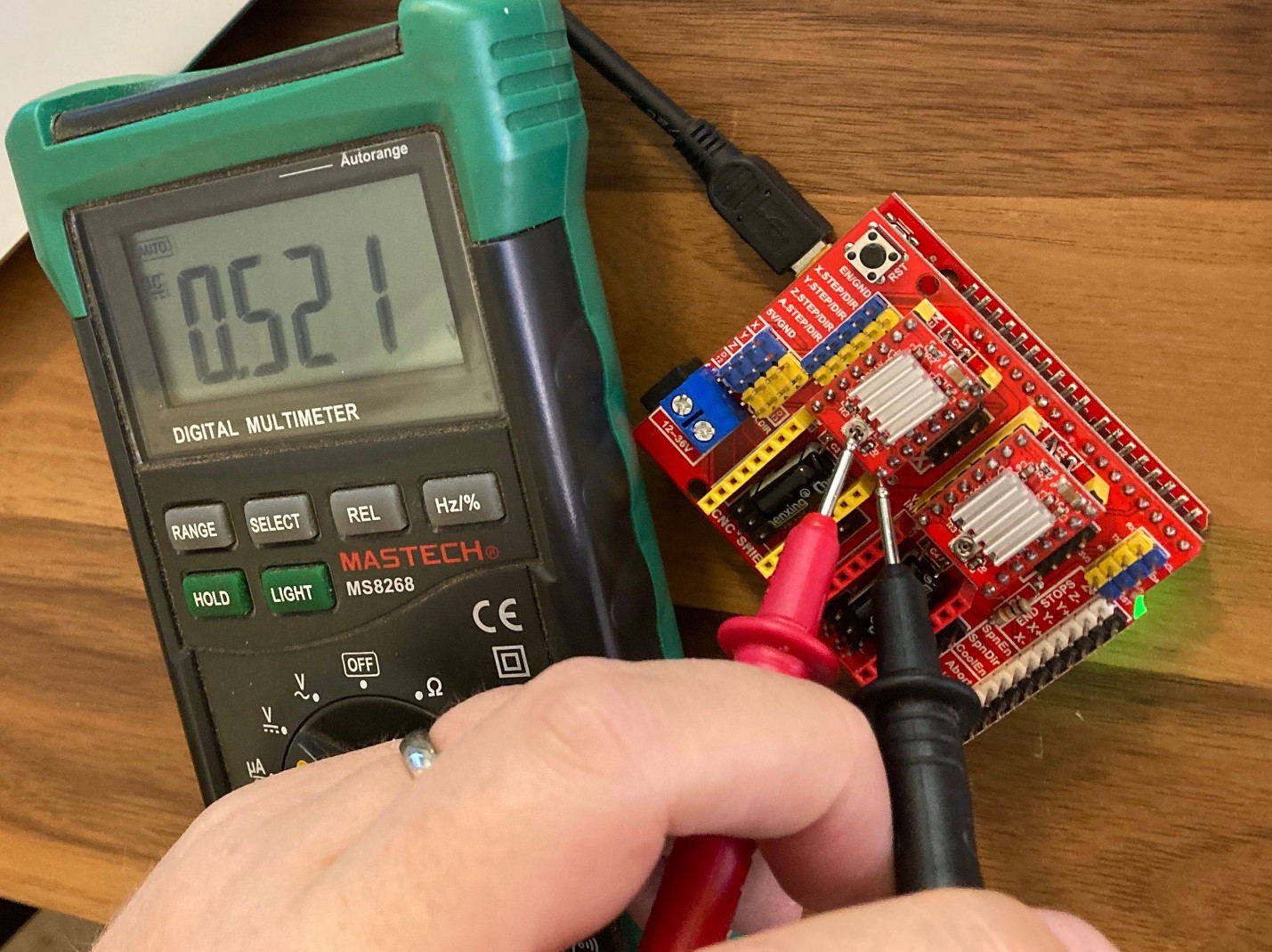
We need to make sure the current is set right for the drivers or we won't get the torque we were hoping for and may cause the driver to overheat. With the stepper motor and stepper power supply disconnected, use a multimeter measure the dc voltage between the trim pot on the driver and the ground pin. Use the above diagram to guide you on where each are located. With the voltage recorded we can use the formulas in the diagram above to work out the current.
For the A4988 the recommended current is 1.17 Amps, but you can try to drive it up to 2 amps, if you provide active cooling. The equation given says that current equals voltage divided by 0.4. In this case 1.17 amps = v / 0.4 or v = 1.17 * 0.4 or roughly 0.5 v.
![]()
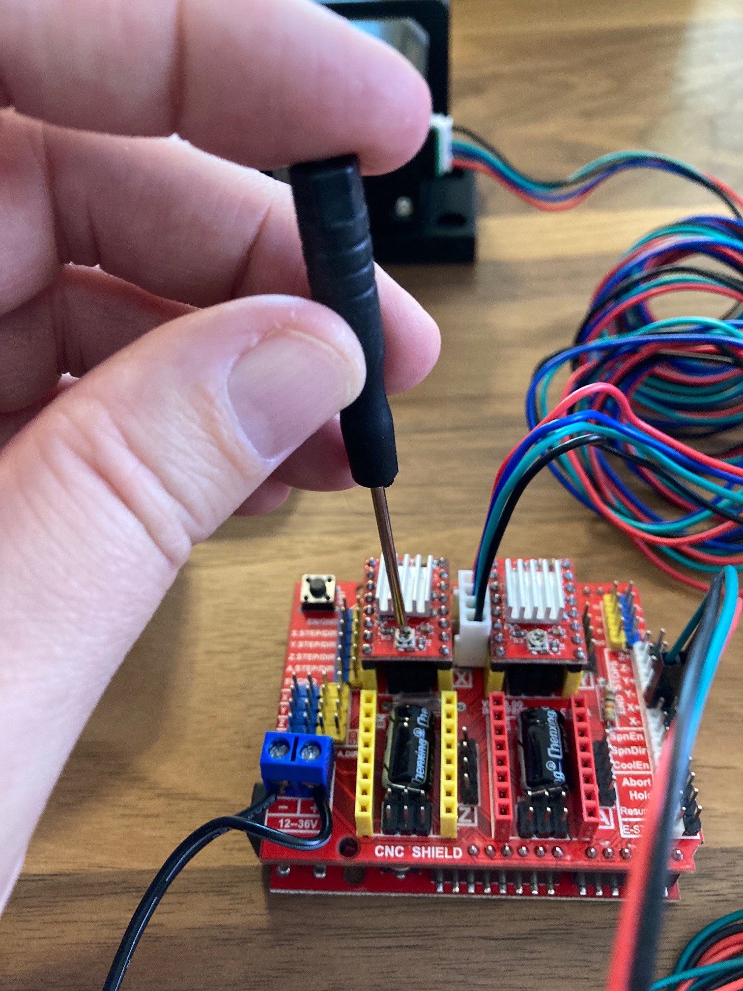
If you need to adjust the voltage, find a small screwdriver and gently turn the trim pot left or right, double checking the voltage as you go. be careful not to damage the pot, or to turn it past its limit of travel.
![]()
With the drivers all set up we can wire in our stepper motor power and plug the stepper motors in as well. Be sure to double check what lead is positive on you power supply. A word of caution, if you need to remove the stepper motor or driver, be sure to unplug the power supply first or you can cause permanent damage to the stepper driver or uno.
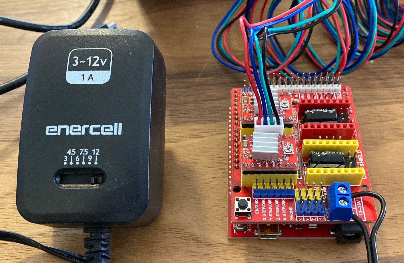
Plug it all in, bring up universal gcode sender, and run the setup wizard to make sure your steppes are working.
Note, the power supply shown here is much too small to really run a steppre motor. It claims to be a 12v 1A power supply, but being a variable power supply it really is a 3v 1A supply, at 12v it can only produce 0.25A, well below the power requirements for even one stepper motor. I can easily stall this stepper motor out with my hand using this supply. You really want at least 3 amps, and ideally 24 volts as well to ensure the stepper motors keep there power when spinning faster.
-
Belt drive
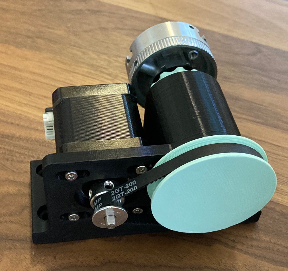
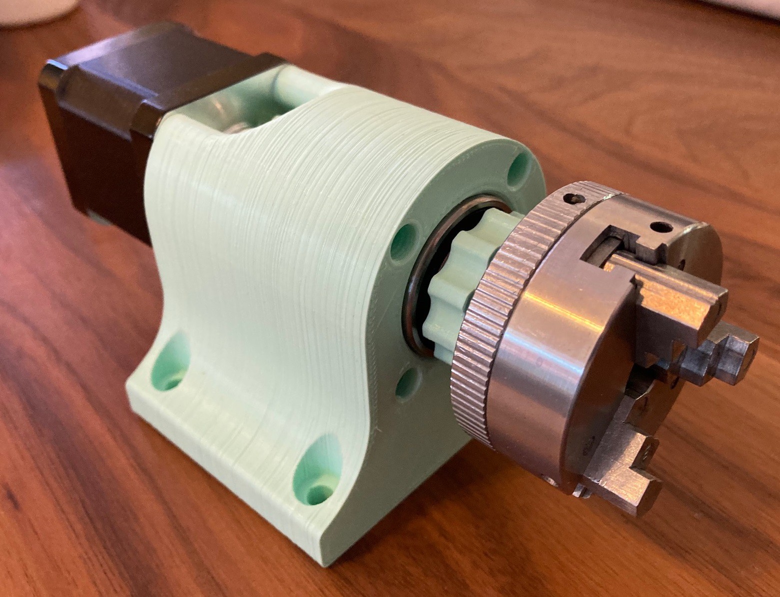
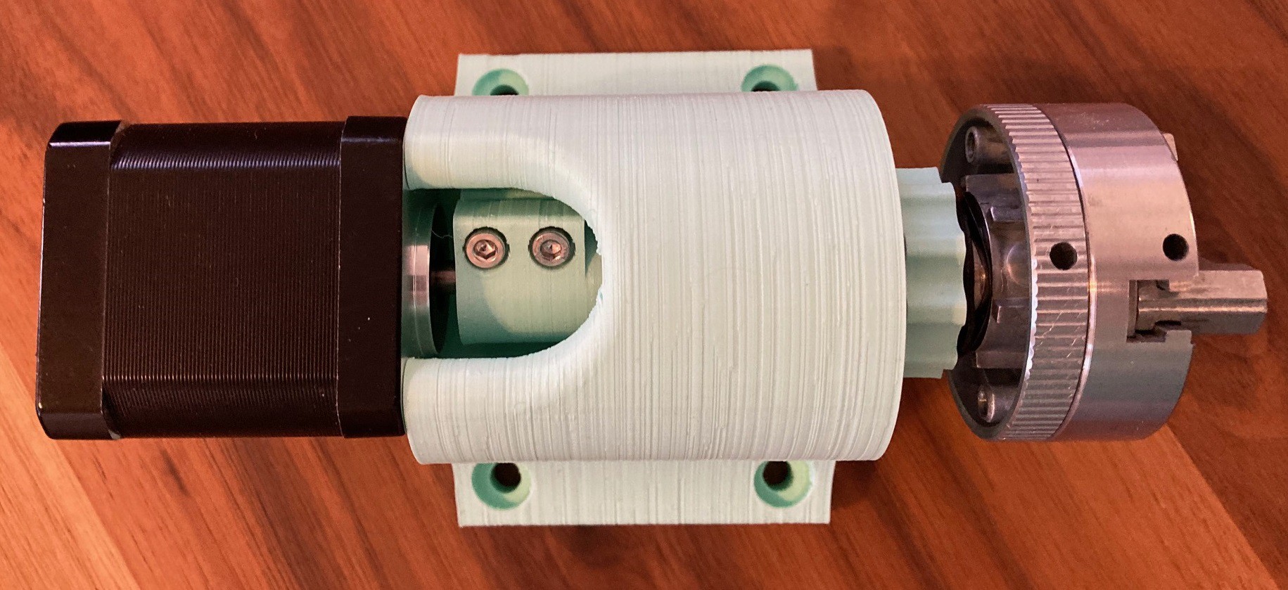
09/18/2021 at 17:38 • 0 commentsIt has been a long slow process, but I finally got my belt drive prototype finished. Modeling the gear was the tricky part, it took several tries and a lot of reading to finally work out how to make it fit the belt perfectly. I will try to do a writeup on that soon.
![]()
I'm still using an off the shelf 3 jaw chuck. My long term goal is to get rid of that and make a few different 3D printed chucks. That should save a bit of cost, and allow me to use a slightly larger chuck, as well as supporting different mounting styles such as a pen vice.
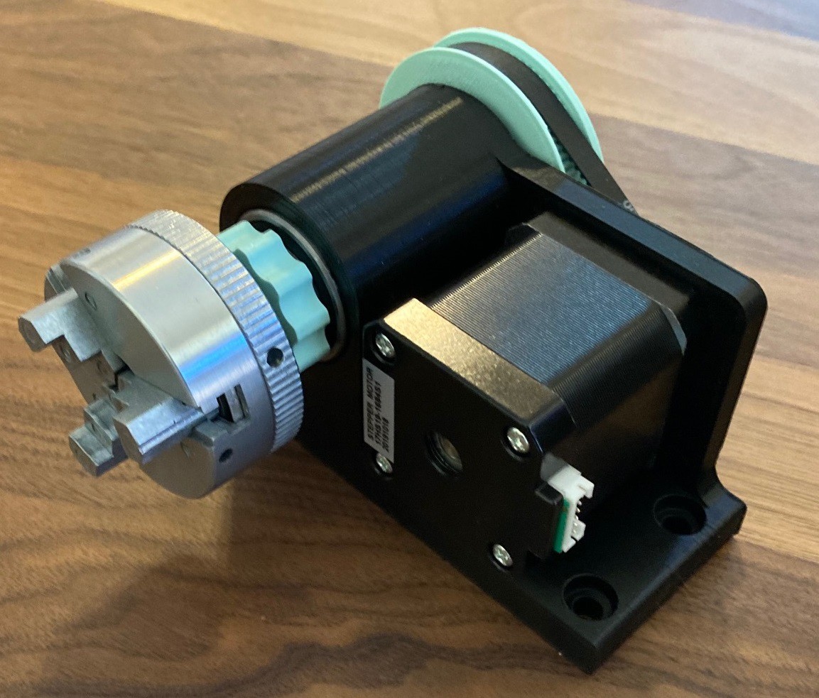
![]()
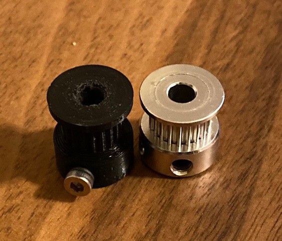
I'm also still using my smaller 20 tooth metal gear. I will try to do a writeup on how to design it in plastic so that you don't need to purchase that gear to build this.
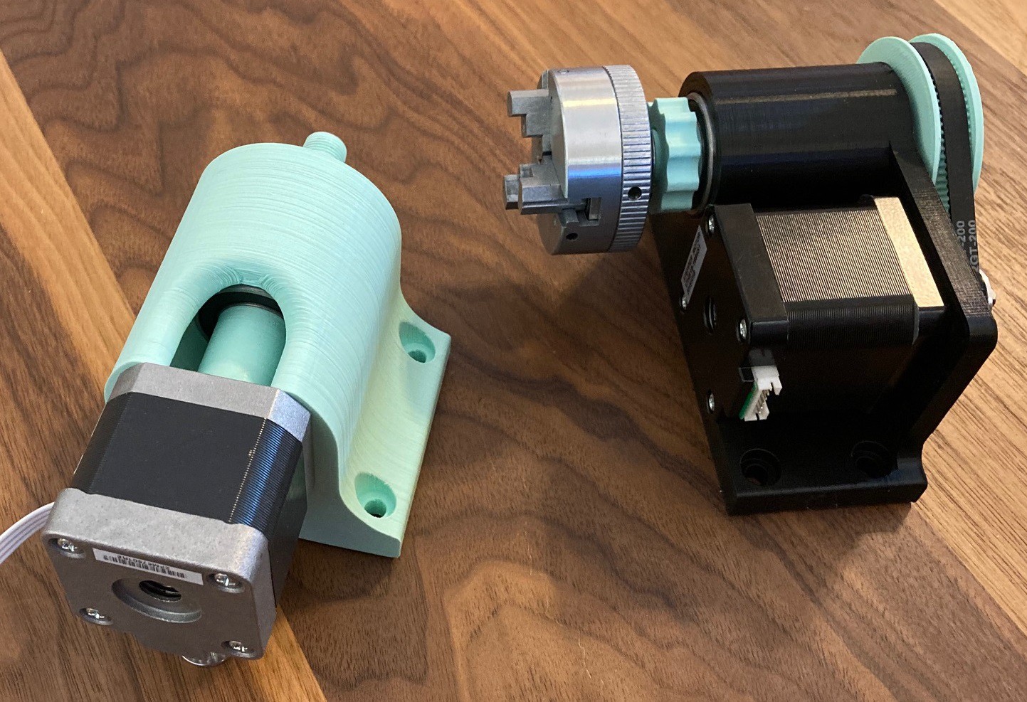
![]()
I still need to do some testing but this feels a bit more sturdy than my direct drive prototype. However the direct drive version is simpler to print and cost less so if we don't need the extra resolution or strength of the belt drive then that will be the winner.
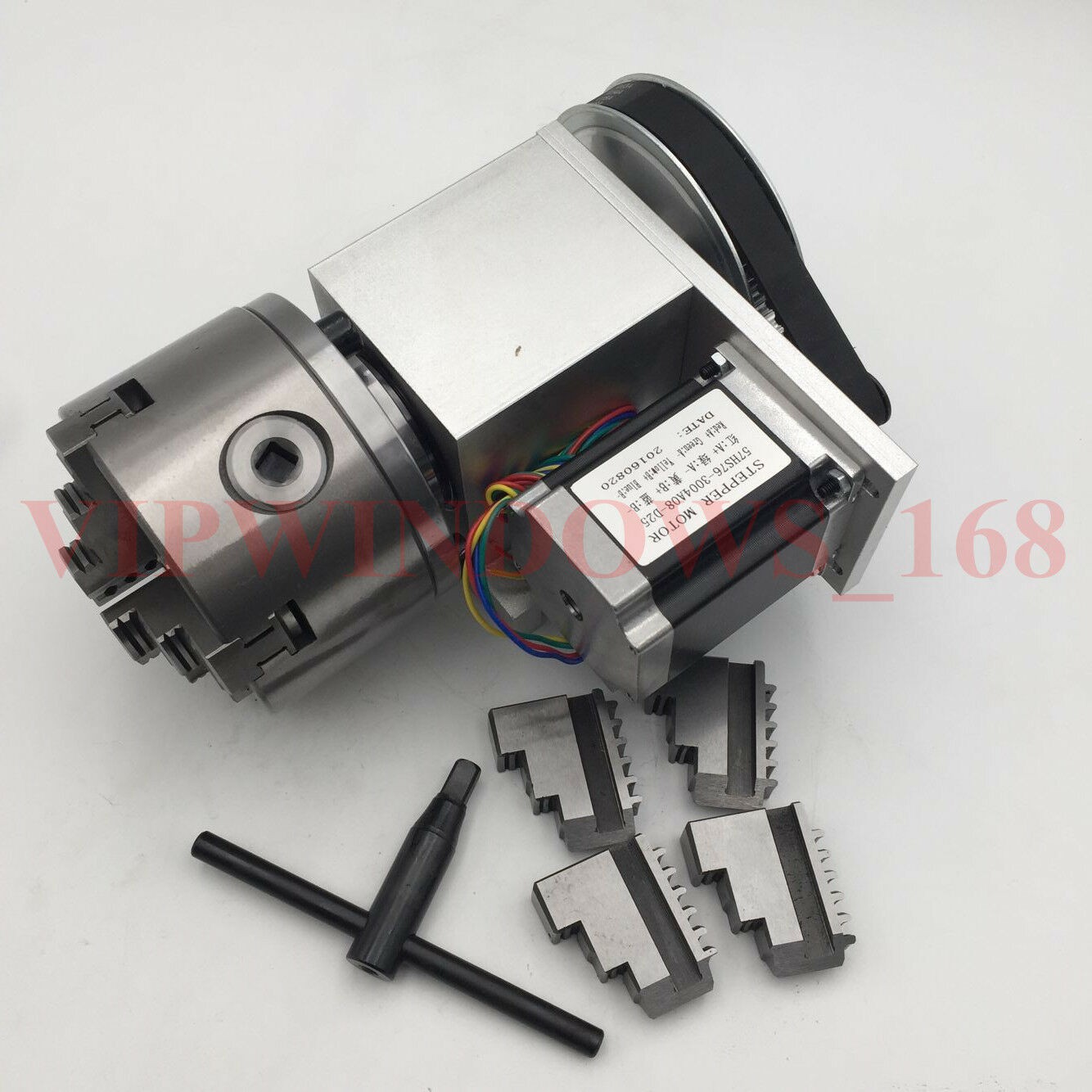
![]()
Once I have a chance to test both of these out I will try and put this all together on thingiverse for everyone to play with. There are still a lot of details to take care of. Not only do I need to mount this, and learn how to drive it, I need to work out some way to swap between the X axis and this new A axis. I have an idea for upgrading my controller to either a RAMPS based board or a more modern 32 bit board running Grbl Mega or Grbl Hal.
-
Small notes
09/12/2021 at 23:14 • 0 commentsI don't have anything exiting to report, but I am working on some future projects.
![]()
I'm still working on my belt driven rotary axis. To help with the design I picked up a 200 mm belt and two pullies, but I don't think I will use the larger pully. I can get a better reduction ratio by printing my own pullies, and it will make for easier assembly in the end as well. Anyway I'm still in the design phase, but right now I'm looking at a 50 mm and 16 mm pully set to get roughly a 3:1 stepdown ratio. I'm just getting started on the design but hopefully it will go smoothly.
![]()
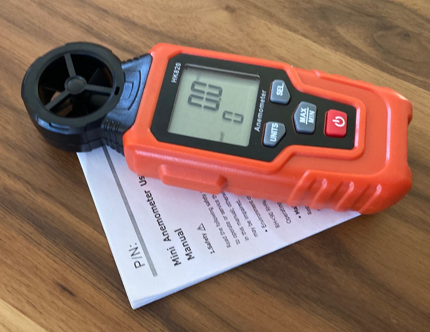
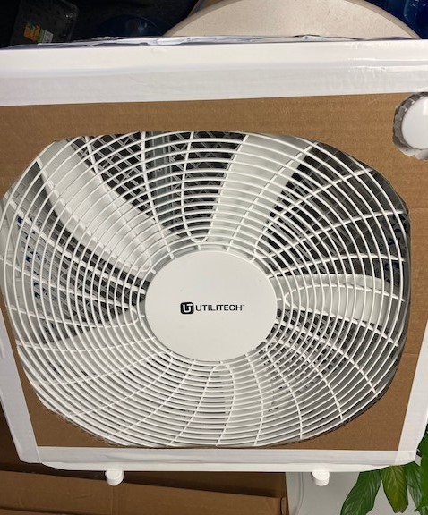
I saw a note the other day about how without a baffle a box fan will reverse the flow of air at the edges. It piqued my interest and so I reached out and picked up a $6 anemometer from Amazon.com. It is crazy what you can buy for next to nothing. I can't remember what the original site was, but it was probably one of Matthias's videos or maybe this filter project. Again I have not found time to really play with this yet, but I did verify that the edges of my box fan are in fact sucking air backwards through the filter. Anyway it should make for a fun distraction, whenever I get the chance to experiment. My plan is to profile the cross section of the fan and verify that adding a baffle it in fact increasing the flow across the full area of the filter.
![]()
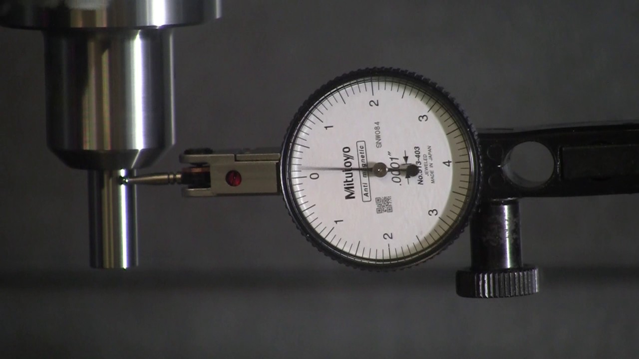
Finally I saw a comment about spindle runout and so it is on my list to look into my spindle to see how much runout I have. I looked into buying a test indicator to make this measurement easier, however the reviews on reasonably priced indicators are poor, so for now I will stick with my dial indicator and see how well that works.
![]()
-
Gyrations
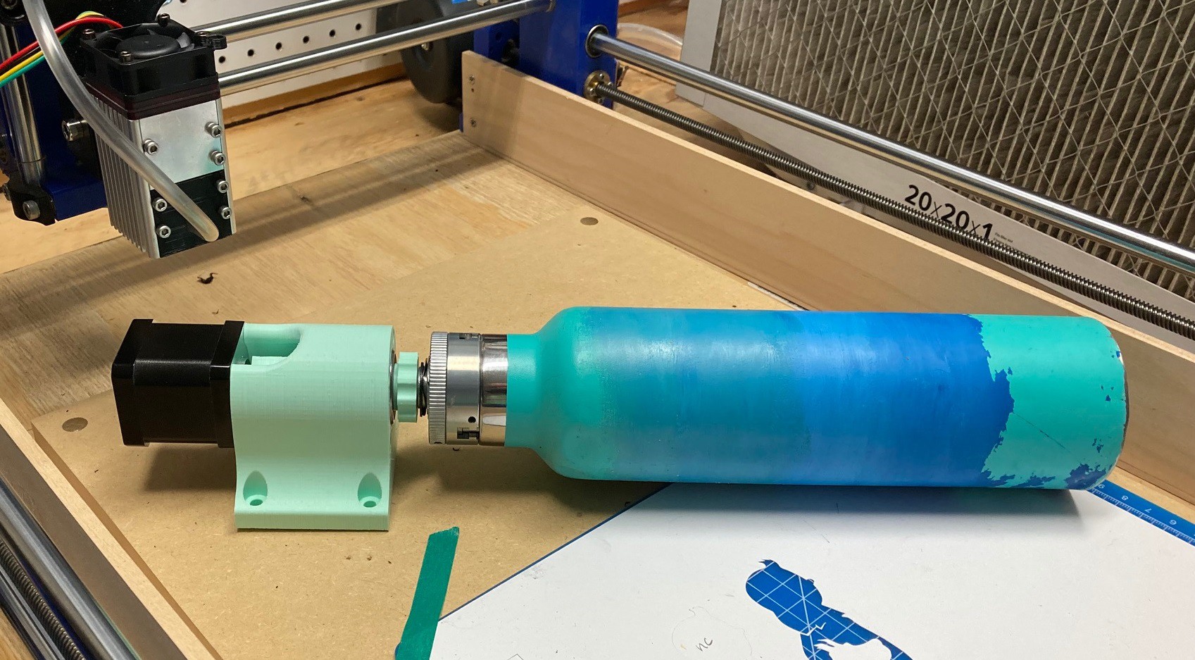
09/07/2021 at 04:40 • 0 commentsI have been contemplating a rotary attachment for a while now but got hung up on the design. In order to shake off my paralysis by analysis I have decided to just print up a few different designs without worrying about them being perfect.
![]()
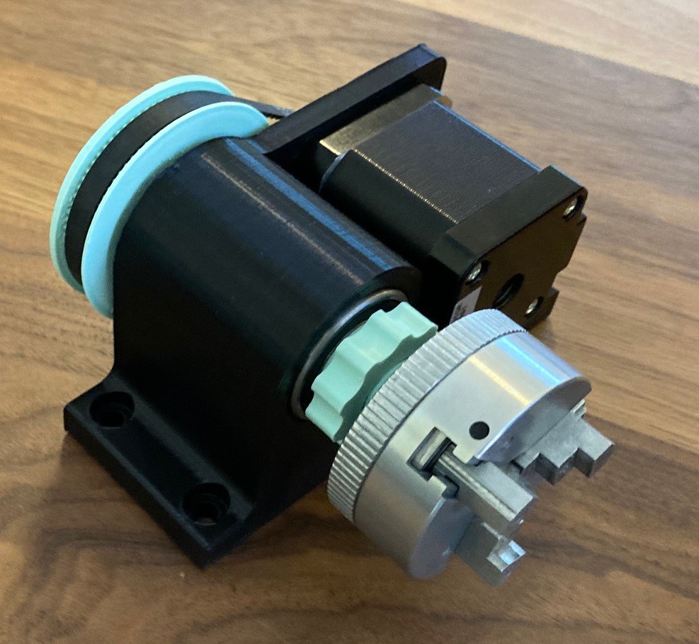
My first design is a direct drive setup with no gearing involved. I'm using a pair of bearings with a 15mm inner diameter and running a 3D printed rod through the middle of the bearings and using a nut to clamp it all into place. The chuck is then threaded onto the rod using its built in M12x1 threading. This is less than ideal but it will do for now.
![]()
I'm using an off the shelf Nema 17 motor that I had left over from my multibot build and the chuck is a little cheap unit I got off amazon for $13.
![]()
With my 90 mm of clearance I can just barely fit the smaller hydro flask on the chuck with enough clearance for the laser to focus.. It would need some sort of a tail stock to make this work but it should be possible to customize water bottles with this setup.
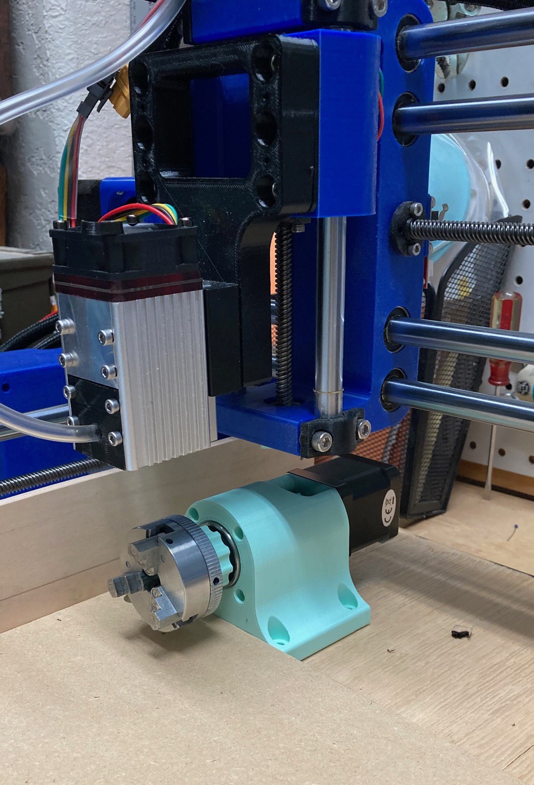
![]()
I'm thinking of mounting this permanently on the back side of my machine, just past the waste board. For larger items I could remove the waste board to get a bit more vertical clearance and for smaller items it would be always ready to go without interfering much with the normal operations of the machine.
There is a lot more resistance to turning this than I thought there would be. It is possible that I could clean the bearings and re-grease them (somehow) to get it to spin more freely. However it is probably best to go with a gear or belt reduction to get more power out of the motor. To that end I have ordered several toothed belts and some metal pullies to experiment with. Although ultimately I would like to dump all the metal parts and make this fully 3D printed except for the bearings and fasteners.
I need to work out a low cost way to add a tailstock that is flexible and does not eat up a lot of working height. I also need to work out the best way to switch the y stepper motor out with the new rotary motor. I probably will apply power to the y stepper when not in use to lock it into place. Alternatively I could physically block the axis, or I could make a separate stepper driver to run either axis and come up with a way to drive it from the computer. Ideally I would have a controller that could drive 5 axis at once, that may be possible by going with the Mega (ramps) style controller and ramps based GRBL build. I need to investigate that some more. With 5 full drivers I could do 4 axis milling, making it possible to make large flat features in round material.
Anyway this is all preliminary work, I have not tested it at all and will probably land on a different solution in the end. But I wanted to make some progress rather than being worried about getting it perfect.
-
More Feed
08/23/2021 at 03:59 • 0 commentsI spent some time trying to work my way through the feeds and speeds section of the Machinery's Handbook. This is a thick read, but it is informative. For one it becomes clear that all the feed/speed info out there is really focused on getting the fastest cut out of the machine at the expense of tool wear. They want you to use the highest spindle speed and fastest feed rates possible.
One output of all this is that the limiting factors include overheating the cutter, stalling out the spindle motor, and chatter/flex in the frame of the machine. I did a quick power calculation and for the bits we can use (1/8" single flute) our 500 watt spindle should be more than strong enough for anything but steel. That leaves chatter/flex of the frame and burning the cutter. Burning can be minimized by taking a correct amount of material on every pass of the cutter (having a proper chip load), and flex is down to experimenting with feed rates to minimize chatter.
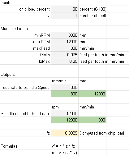
After running many different calculations using values from many sources I have come up with the theory that all that really matters is the chip load. Once we have an idea of how much of a cut we want to make on each revolution (how large the chips will be) we can then take a stab at the best feed rate and work out the matching RPM (or the other way around) to produce a clean cut within our machines capacity.
I made a new calculator (on sheet two) that can calculate feeds and speeds based on only the number of teeth on your bit, a percent of chip load (0 percent is a very thin chip, 100 percent is a very thick chip), and either the desired feed rate or RPM. The output will be the missing value, all limited to the ranges that your machine can support.
I need to sit down and run these numbers through some real world testing to see if my theory holds any water, but if it works this would be a much simpler way to think about all of this for our particular machine.
-
Feeds-n-Speeds
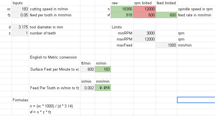
08/20/2021 at 04:01 • 0 commentsAfter stumbling onto this article by Niko Plath I started to look into speeds and feeds again. Every time I look into this I get confused. There is a lot of talk about it, but the numbers never seem to have much meaning.
Anyway I took the formulas from there article and made a google spreadsheet that lets you play with the numbers. The first set of numbers (vc, fz, d, z) are the normal inputs for speeds and feeds (in metric), those all derive from the cutter and its capacity to cut material (its base hardness and geometry).
In addition you can add limits on the spindle rpm and the speed of cut (minRPM, maxRPM, maxFeed). If these limits are applied then in the output I mark the affected columns in red.
Finally there is an English to Metric converter at the bottom so you can easily deal with english feed and speed numbers if you find them online.
It is interesting to put in various parameters and see the results. What you quickly realize is that for the limits of this machine you really always end up limited by the max spindle rpm. And if that was not the limit then you would quickly run into the max cutting speed limit. Basically in almost all cases you wan to set the spindle speed to the max.
In addition, playing with the tool diameter and number of teeth it quickly becomes clear that 3mm diameter tools with a single flute are the best choice. We could go up a bit on the diameter, and possibly support two teeth, but going any higher puts it well past the capacity of the machine.
I need to dig into this some more to see what else we can work out about feeds and speeds.
Further reading:
https://www.itc-ltd.co.uk/wp-content/uploads/2015/11/formulae.pdf
http://catalog.eoasaw.com/Asset/Amana%20Aluminum%20O%20Flute%20Feed%20Chart.pdf
https://www.the-carbide-end-mill-store.com/Feeds-and-Speeds.html
https://webseite.sorotec.de/download/fraesparameter/cutting_param_facemillcutter.pdf
-
Choices
08/18/2021 at 23:50 • 0 commentsSomeone asked me what laser module I would buy today, here is my response.
There are three modules that are worth looking at:
- The N40630 30w module that I have for $80 (https://neje.shop/collections/all-products/products/30w-laser-module).
- The A40630 30w module with the FAC lens for $140 (https://neje.shop/collections/all-products/products/neje-a40630-laser-engraver-cutter-module-kits-fac-7-5w-output).
- The A40640 40w module with the FAC lens for $260 (https://neje.shop/collections/all-products/products/40w-laser-module-laser-head-for-cnc-laser-cutter-engraver-woodworking-machine)
The N40630 module is by far the best deal, and I really like it. It can cut through wood up to 3mm without much trouble, and with enough time and effort it can just barely make it through 6mm of wood. The price is right, it really is a no brainer as an add on.
You may want to consider upgrading to the A40630, the price is 75% more than the N40630, but the FAC lens should square up the laser dot, and in theory it should cut with almost twice as much power as the N40630. I can't find anyone online who has tested this module, so I have no evidence that it works better.
And then there is the A40640 module. This uses two of the laser diodes from the N40630 module, and uses the FAC lens. In theory those together should give you 4x the cutting power of the N40630 module for a little over 3x the price. Again I can't find anyone that compares this module to the N40630, or really to any other module. However there are reports that it can cut through 6mm wood in a single pass at a reasonable speed so I suspect it does at least have 2x the cutting power of the N40630 module.
What one to buy? That depends on how much money you have, and what you expect to do with this laser. If you are into etching then look at the A40630, it is not too expensive and should make as nice an etch as any module can because of the small dot size. If you are interested in cutting thick materials, or $260 is not a lot of money, then get the A40640 module because it has the most capacity. And finally if $100 seems like a lot of money, or your just curious then go for the N40630 module and be happy that you got a good bargain.
MultiBot CNC v2
A low cost 3D printed CNC that can be built with minimal tools yet is capable of great things.