-
1Hardware Setup
First, print all of the STL files in the STL folder on your 3D printer. Make sure to print the Measuring Stick in very high quality, or threading the wires will be very difficult.
-
2Assembling the Measuring Stick
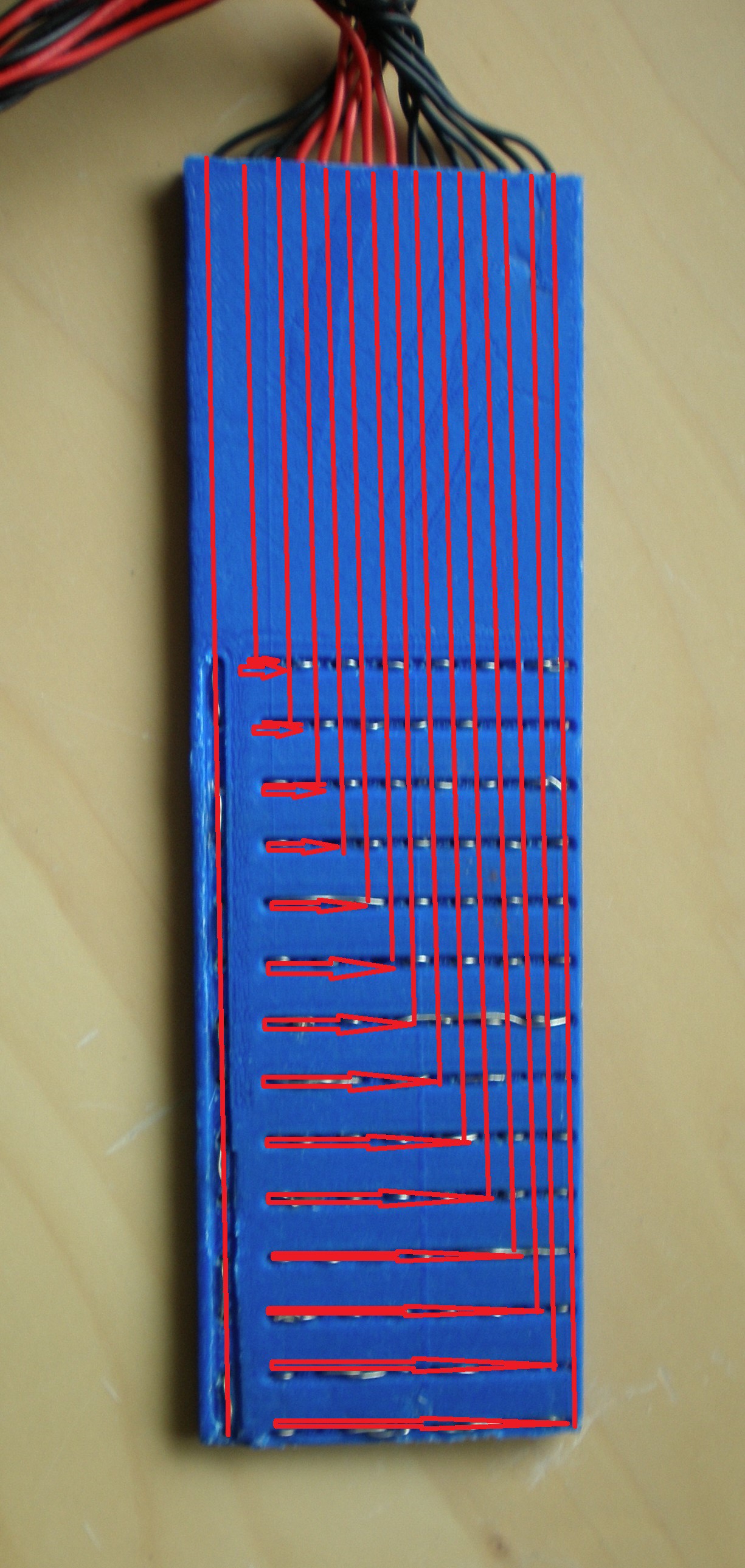
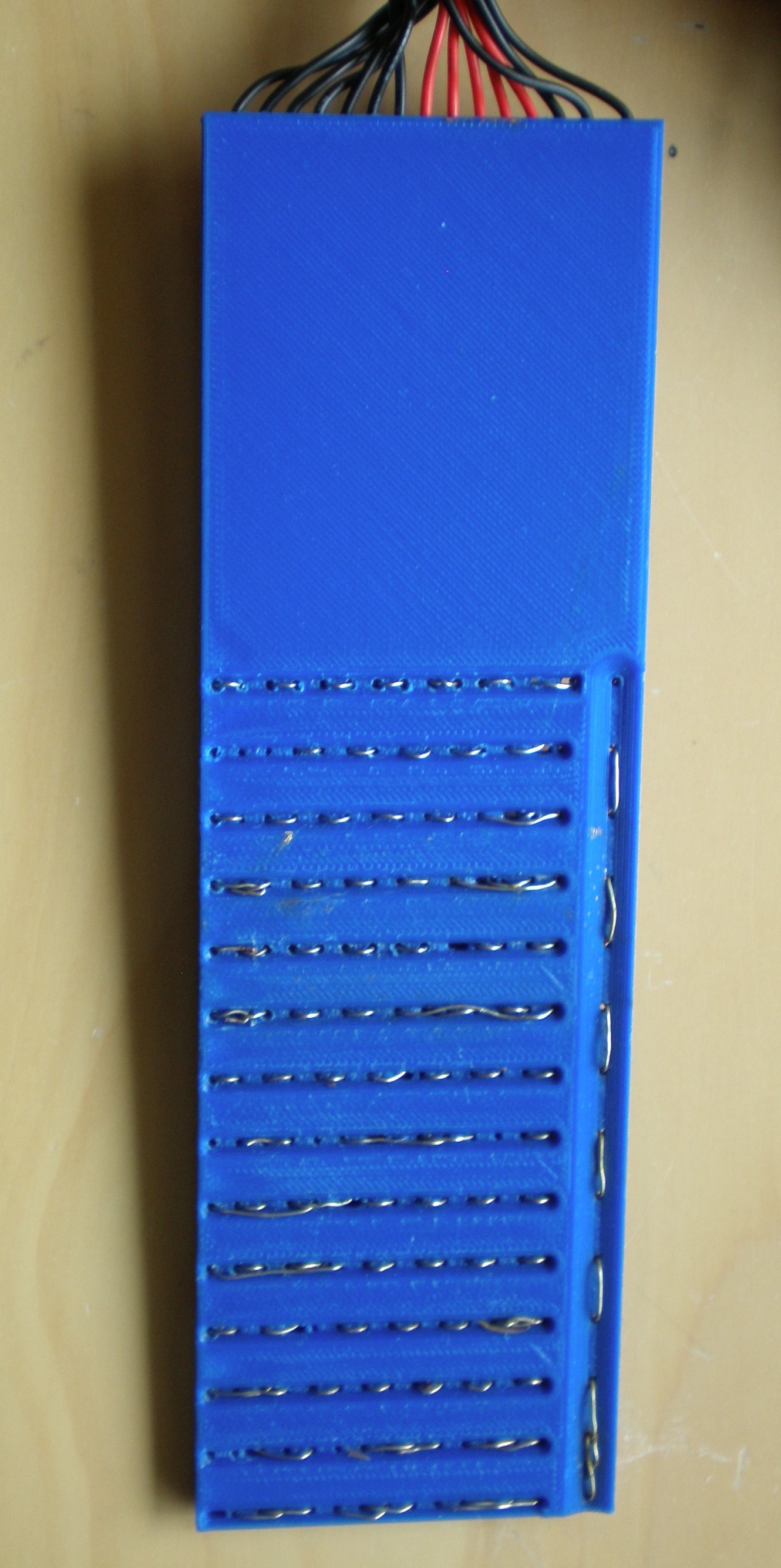
Strip a few inches of coating off of a piece of the single-core wire. Next, thread this into one of the holes on the Measuring Stick as shown by the red lines on the picture below. Once the end of the wire appears in the correct horizontal strip (one with the red arrows), hook it out using a skewer or metal pick and weave it in and out of the holes. Then repeat those steps for the rest of the holes, until it looks like the picture below. This is a slow and painful process, but you should hopefully not have to do it again!
-
3Assembling the LED Stick
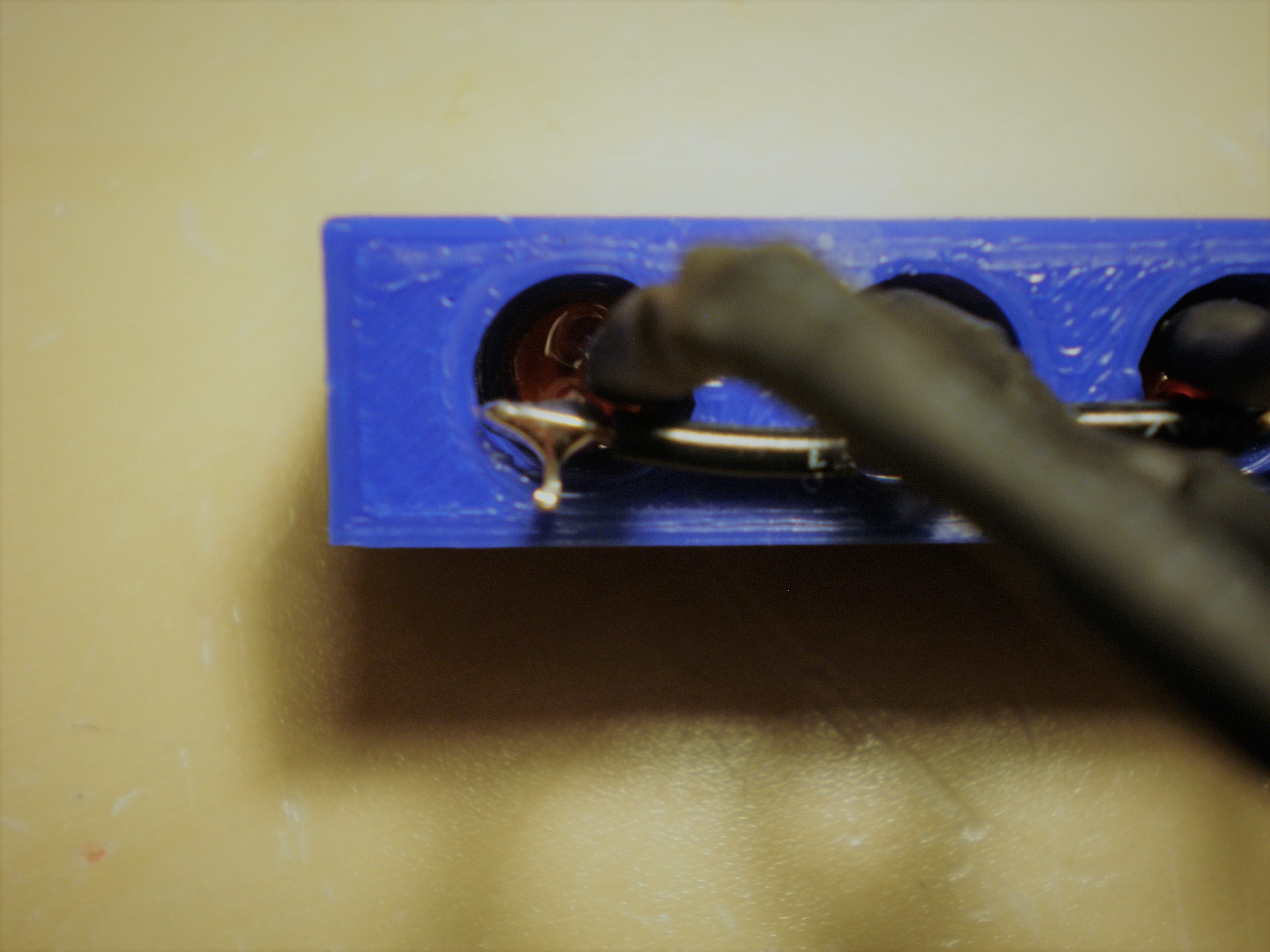
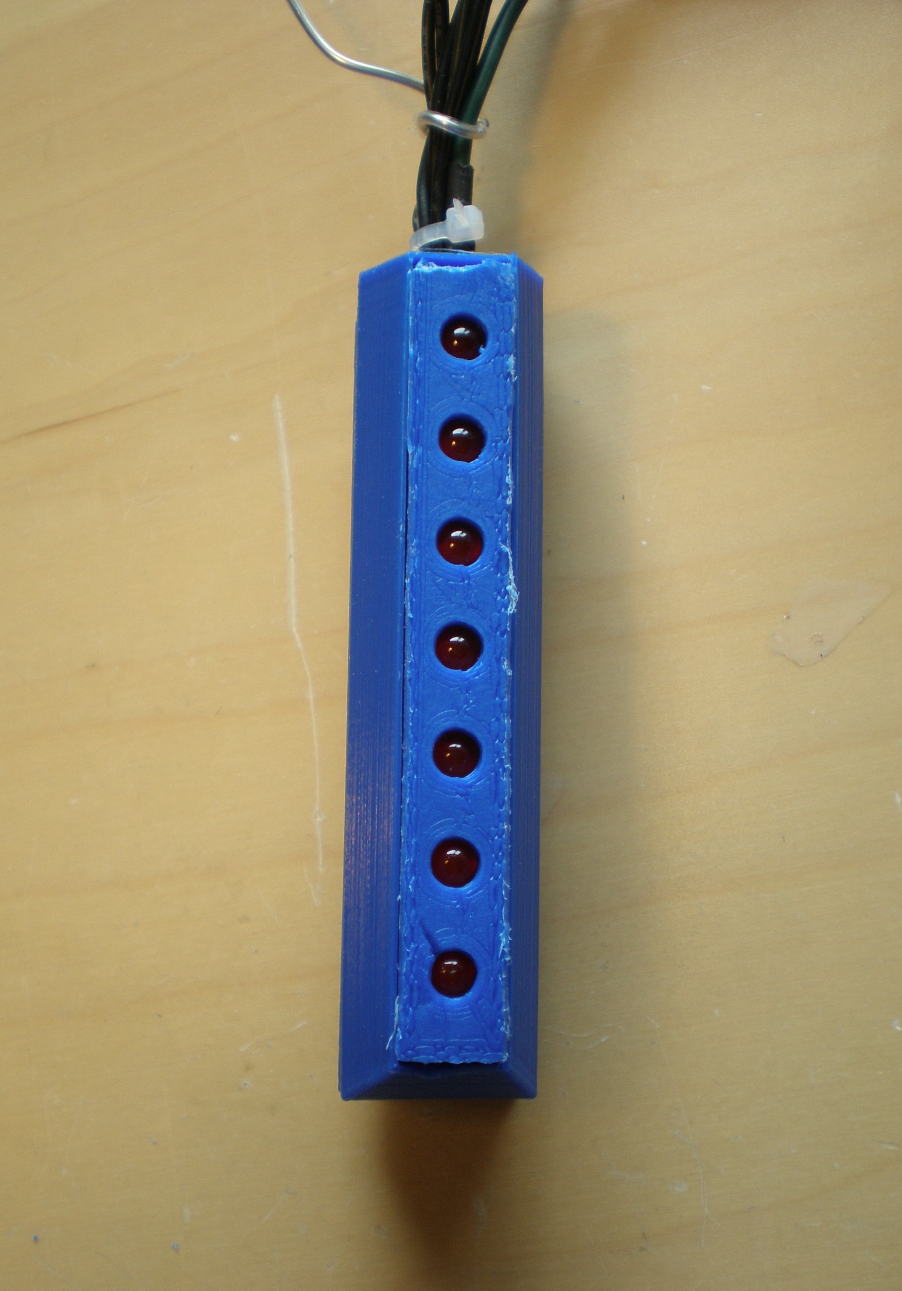
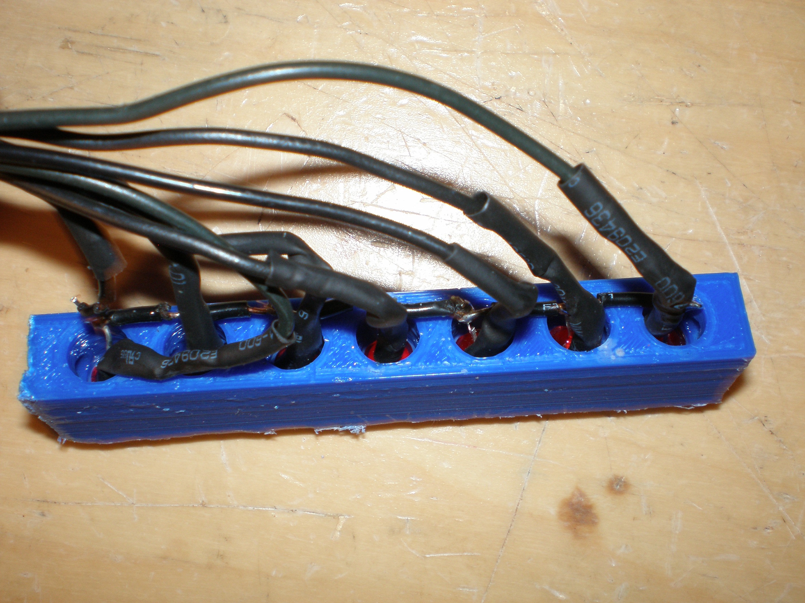
Next, we can assemble the LED stick. First, insert the LEDs into the top part (it should be a snug fit - otherwise, add some clear glue/epoxy). After the LEDs are in or the glue has dried, solder them up as shown below (with the grounds connected together and a separate wire going to each LED's positive terminal). Thread the wires through the bottom portion of the stick, and push the top part down into the bottom part to create the finished part. (This should be another snug fit. If not, as before apply some glue.)
-
4Assembling the Raspberry Pi Case
Finally, we can install the Raspberry Pi.
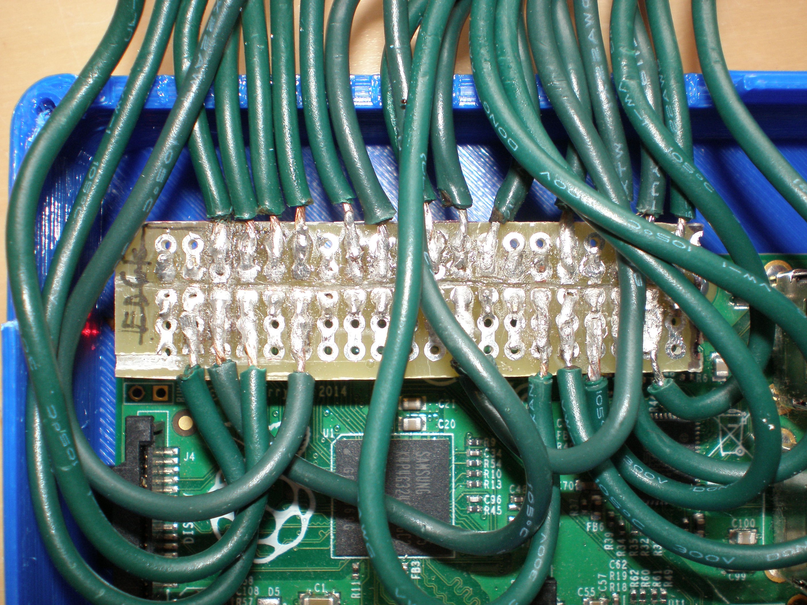
First, solder the wires and a 2x20 socket (on the underside, not visible in the pictures) to the strip board. Use the wiring diagram PDF and the picture below to guide you! If you do make an error, do not worry too much. You can easily change which pin goes to which function in the scripts in the scripts directory.
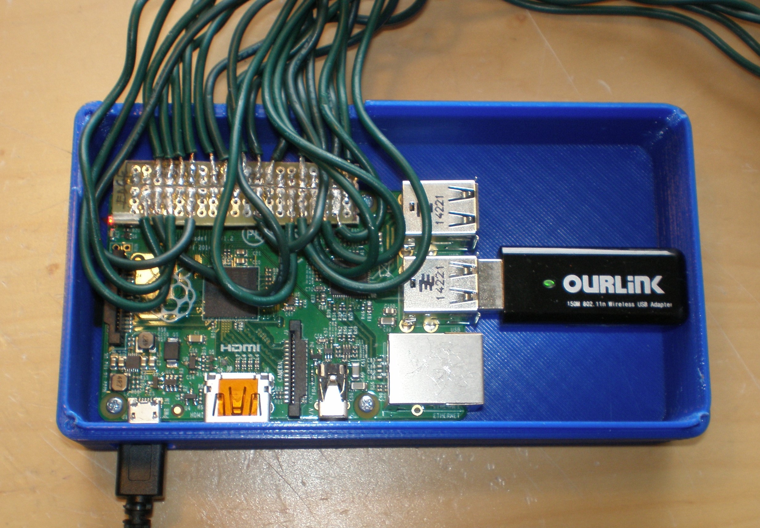
After this, insert the Raspberry Pi into the case, screw in the screws, and plug in the socket. Route the wires through the slot in the side and close the lid. The final step is the add the screws.
-
5Software Setup
See the software setup guide with the source code on GitHub. Once the software is set up, shutdown the Raspberry Pi, disconnect the peripherals and place it under your Christmas tree. Insert the measuring stick into the water base and make sure
that the LEDs are clearly accessible. Then, plug in the power again and your Raspberry Pi Christmas tree water level monitor is ready for use.
Tree-Pi: Raspberry Pi Christmas Tree Monitor
A Raspberry Pi-controlled water level monitor and alert system for Christmas trees
 Alex Mous
Discussions
Become a Hackaday.io Member
Create an account to leave a comment. Already have an account? Log In.