lion mclionhead
-
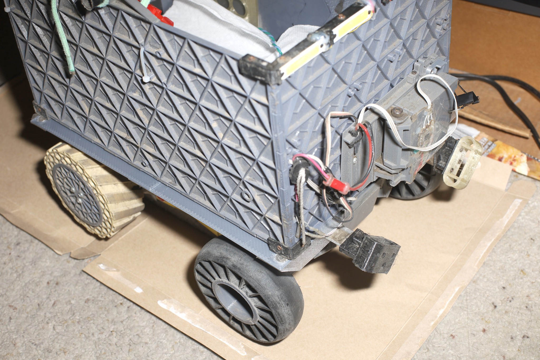
Upgraded motor assemblies, waterproofing structures, steering structures, tail lights, camera mounts
06/13/2026 at 23:21 • 0 comments![]()
![]()
![]()
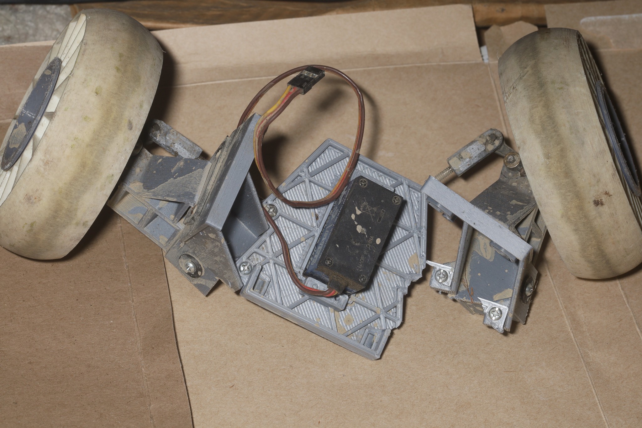
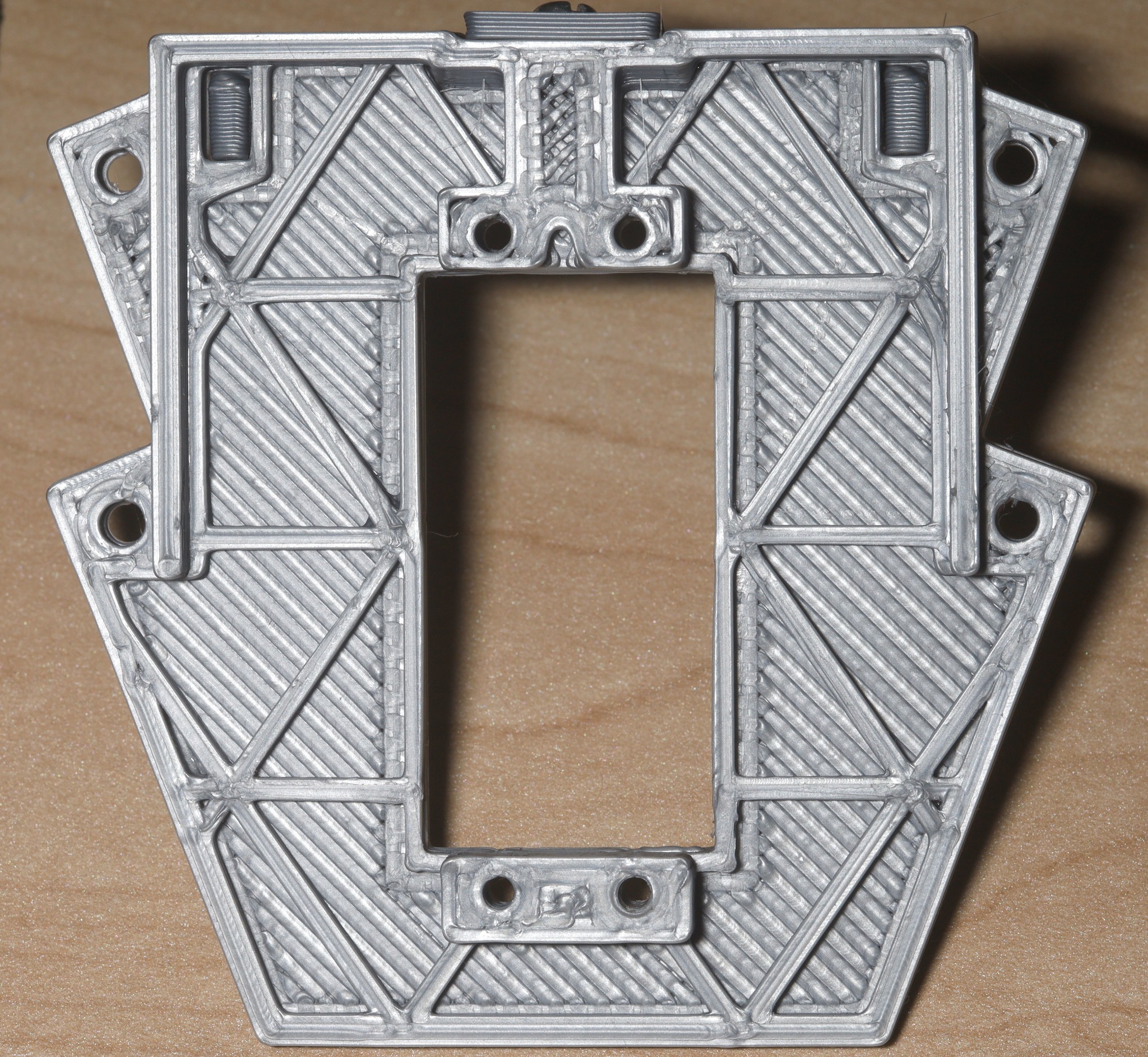
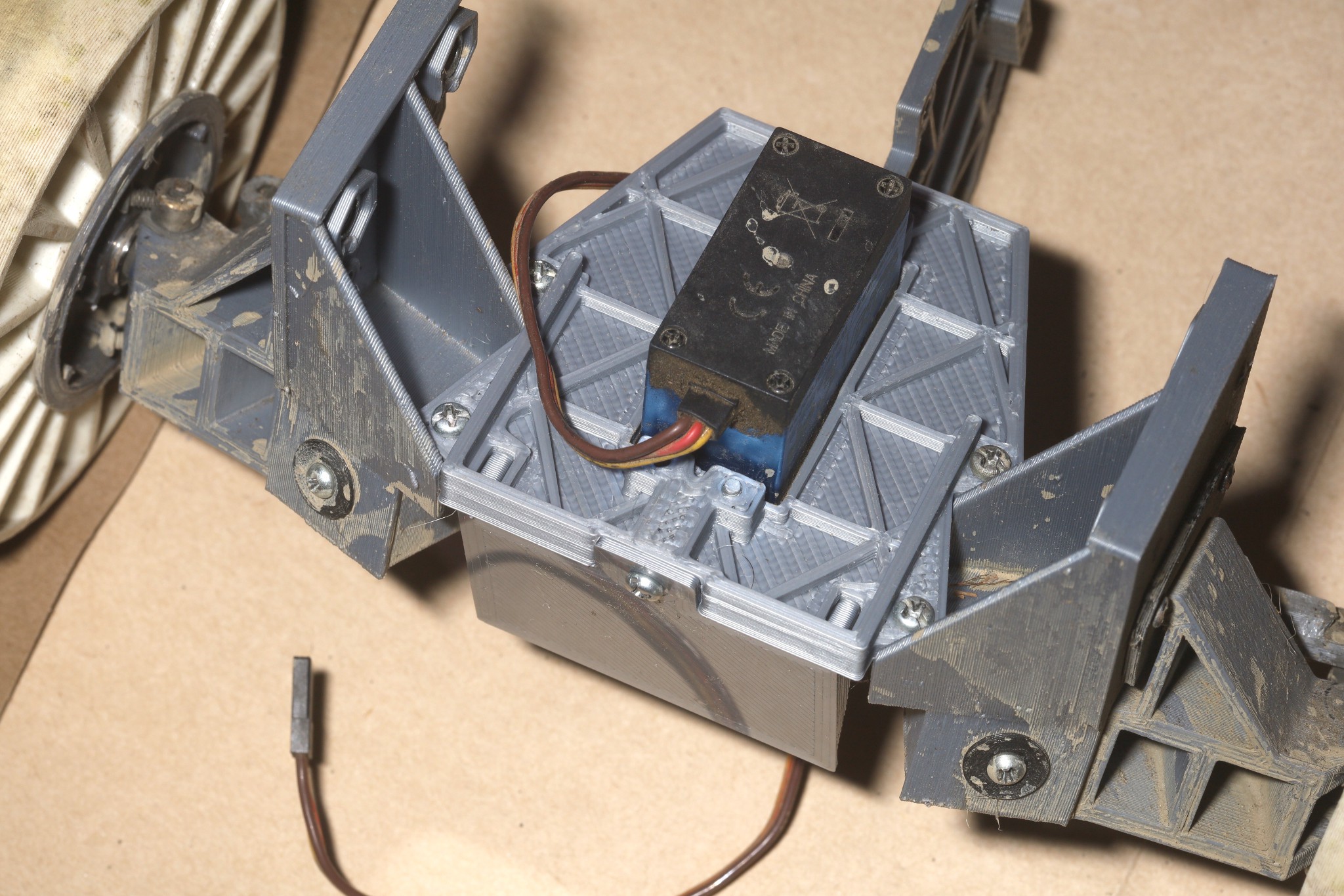
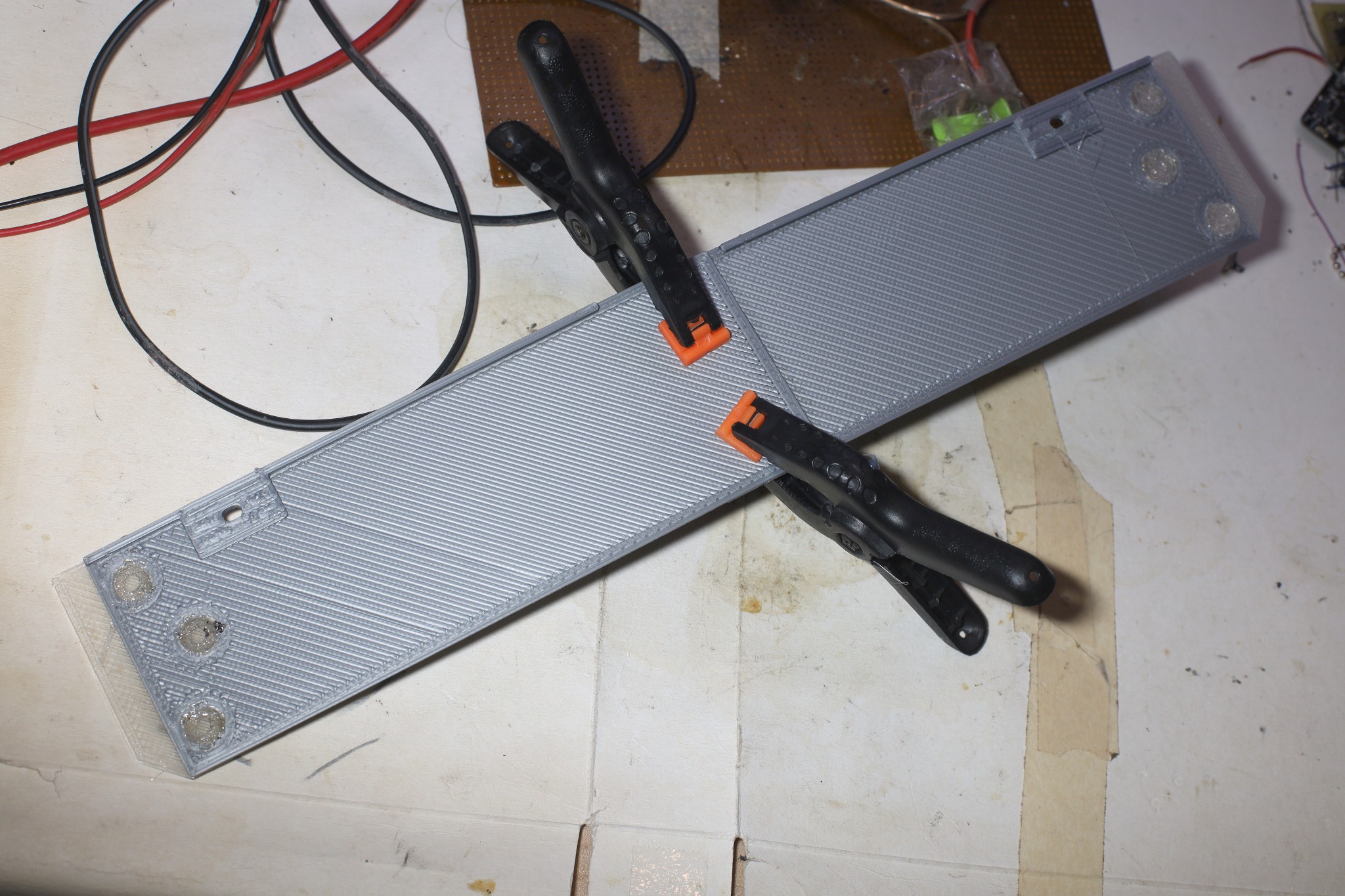
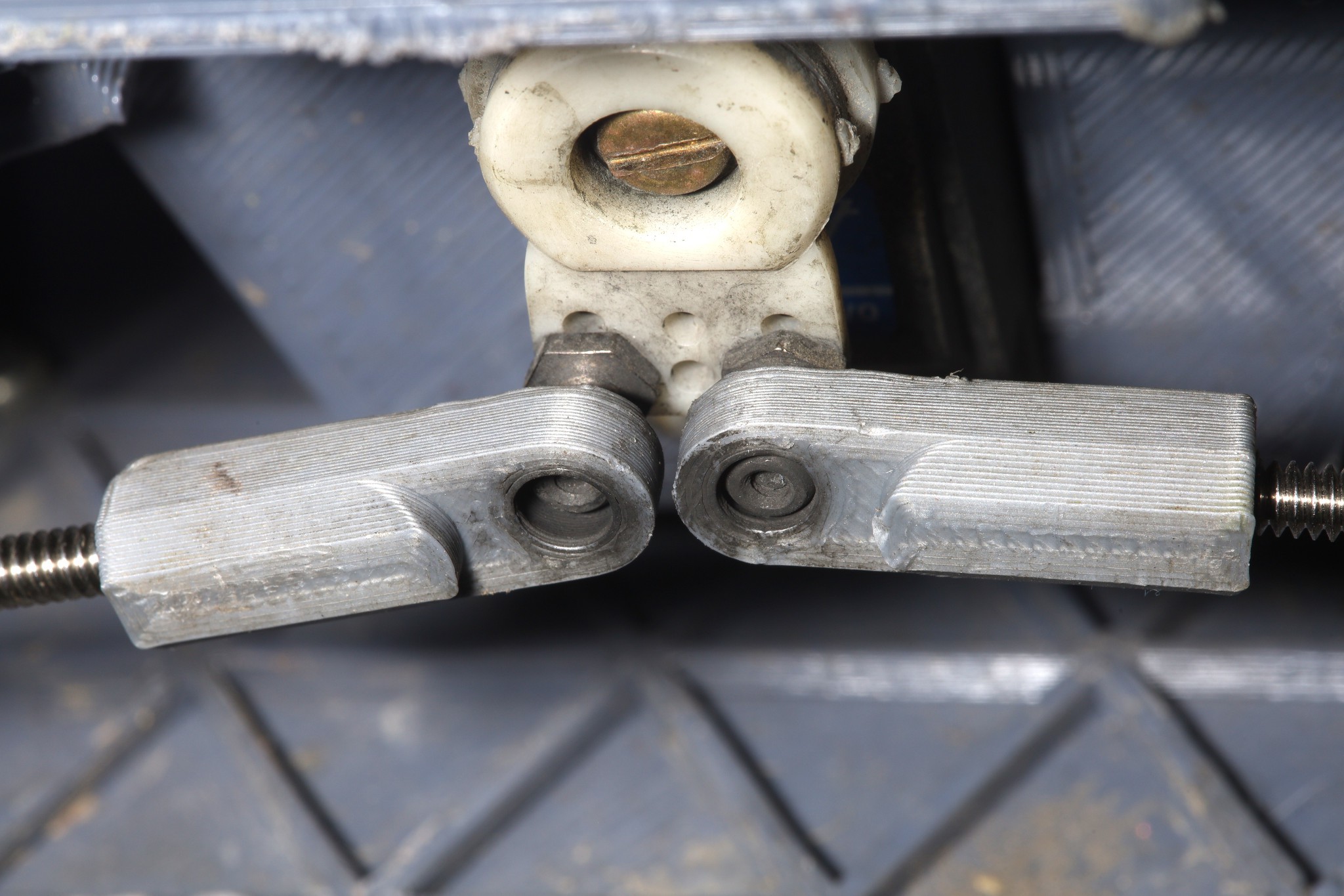
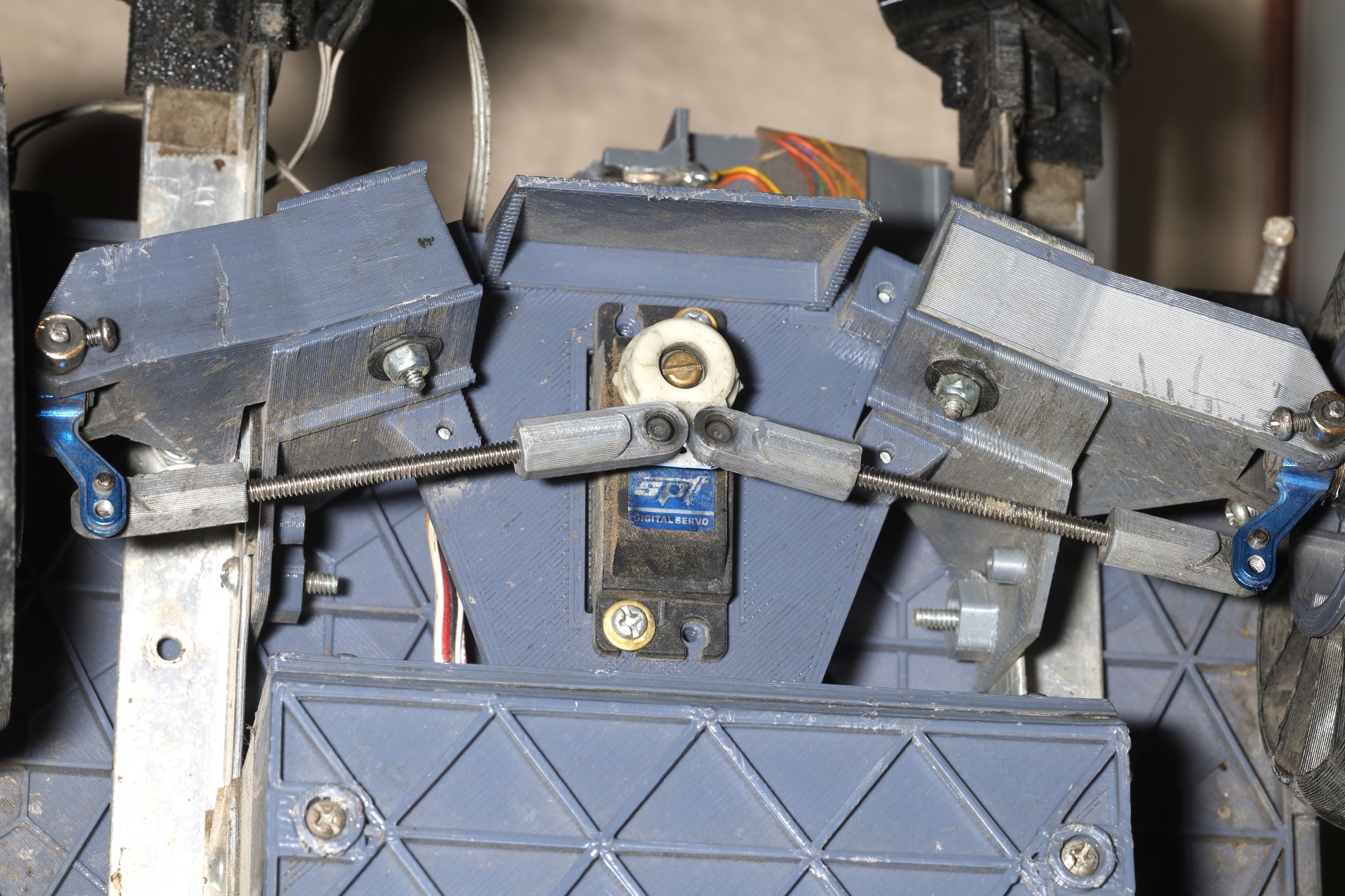
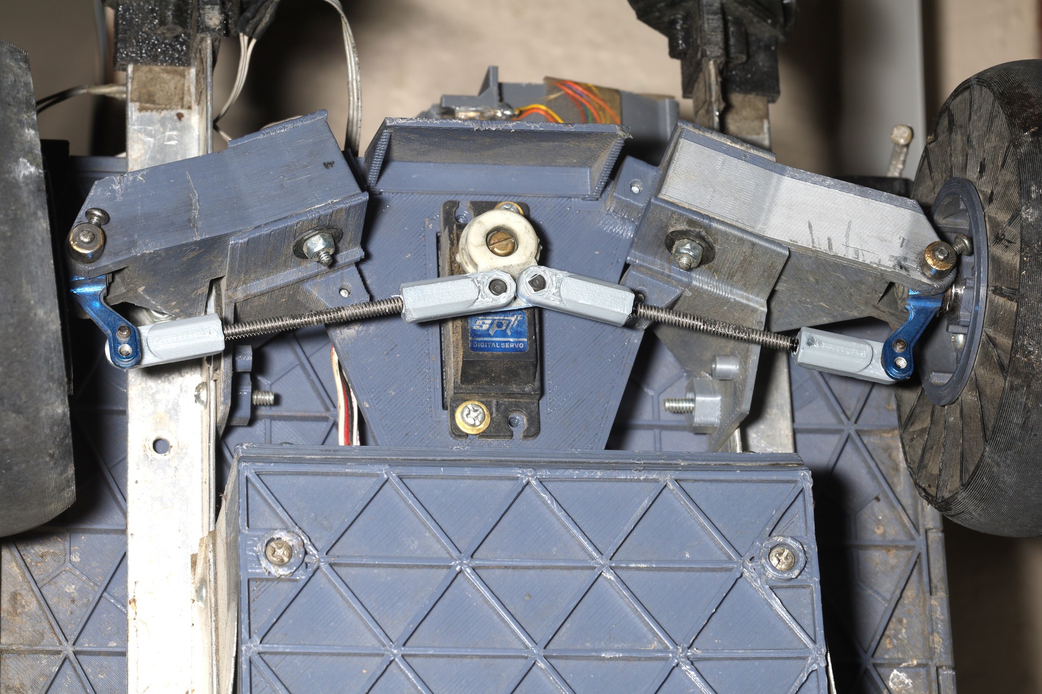
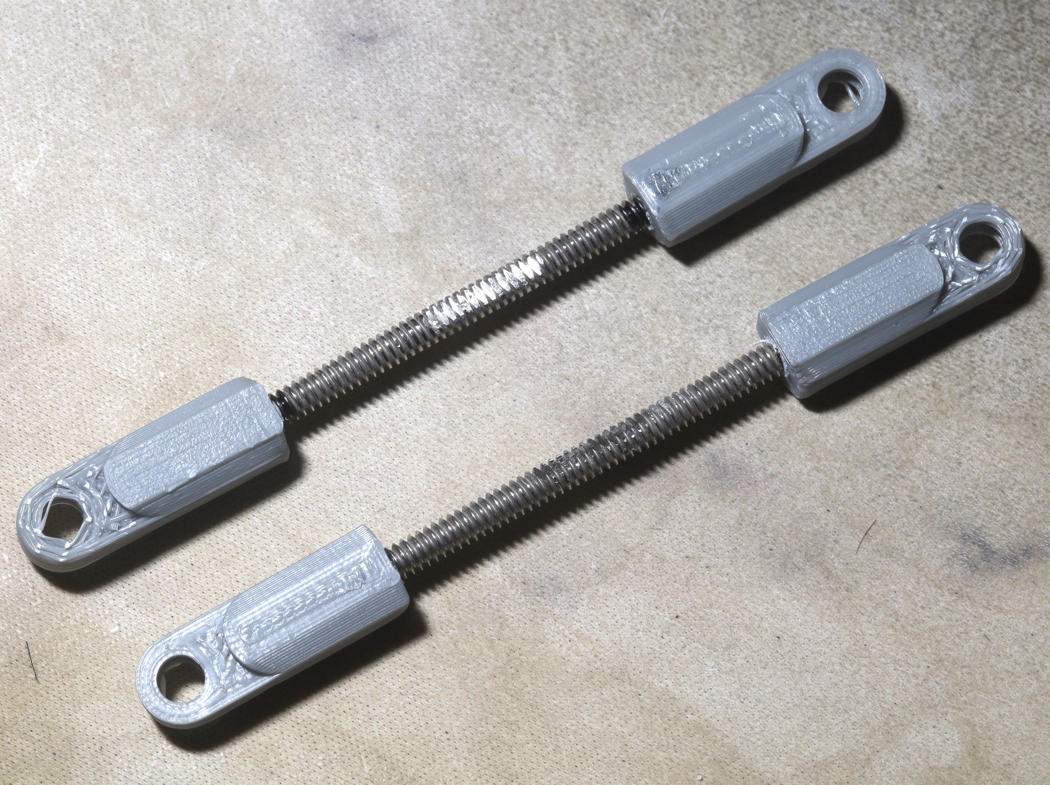
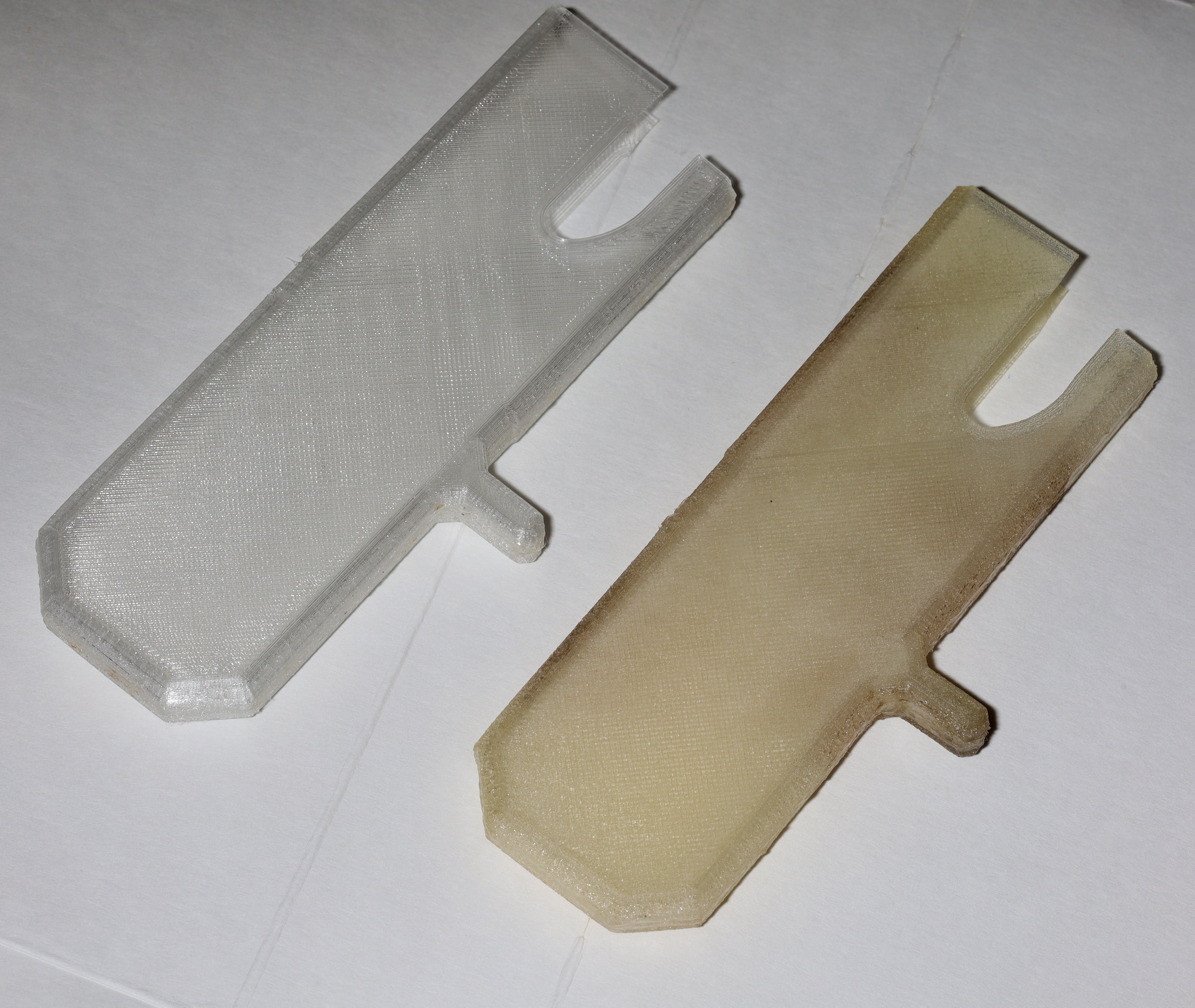
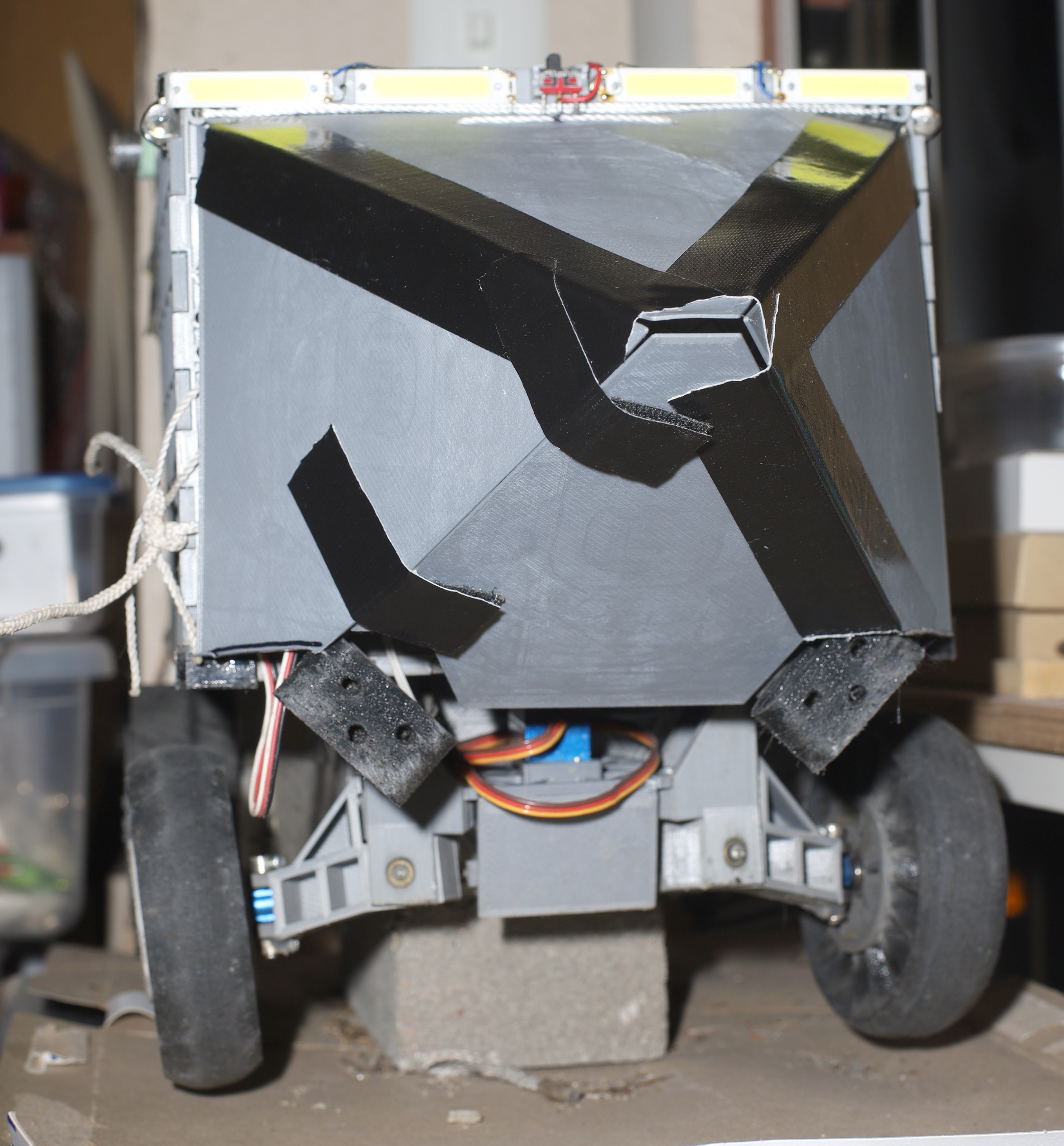
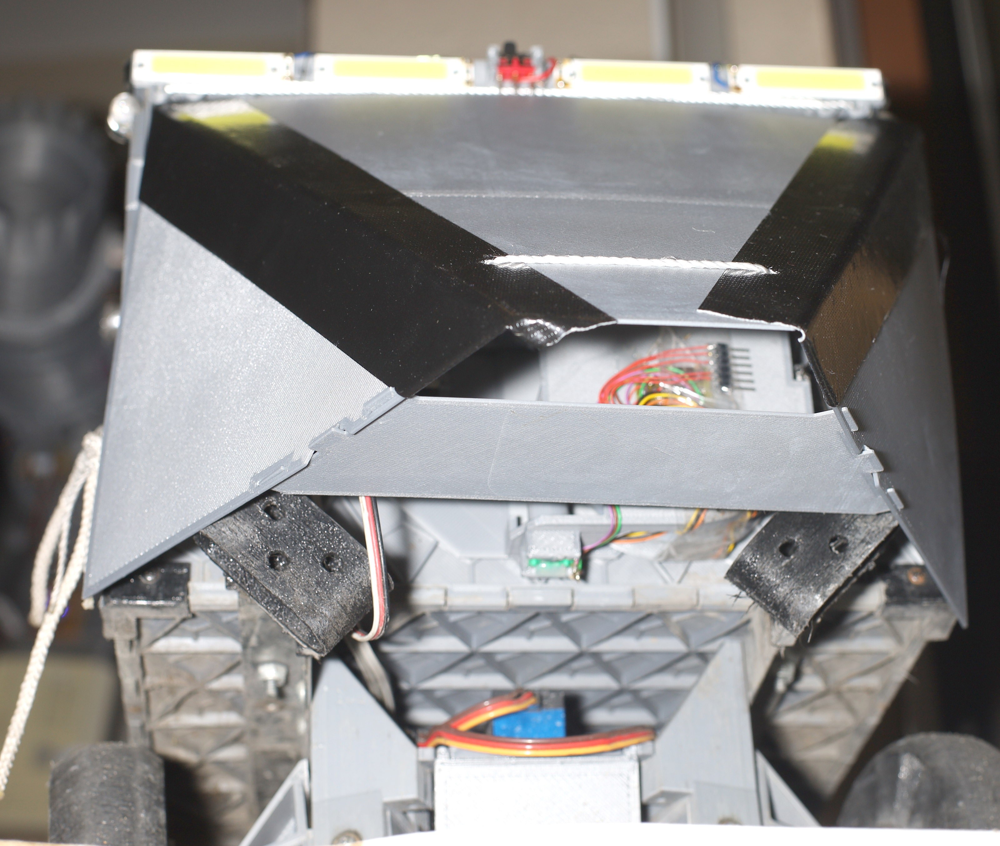
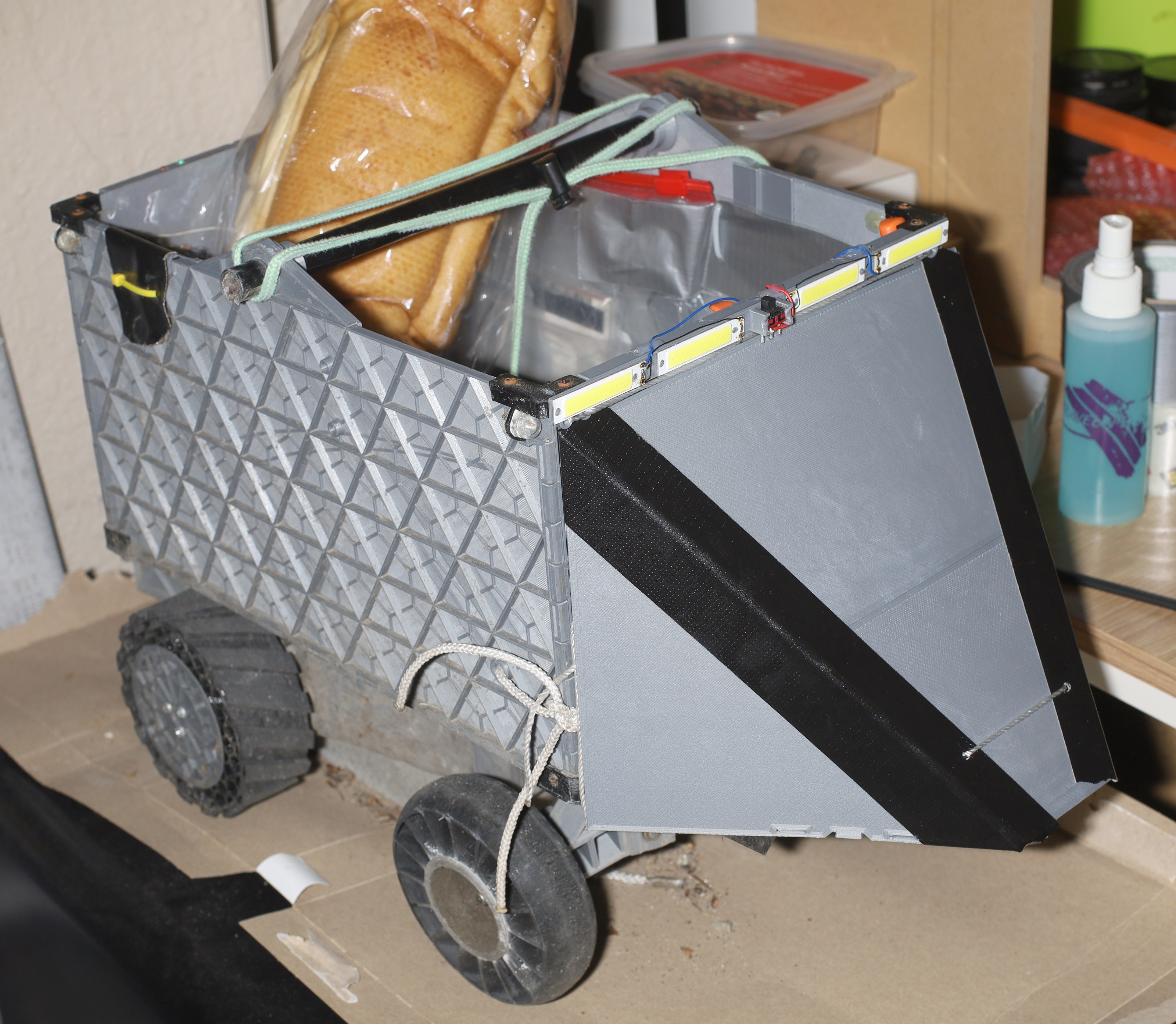
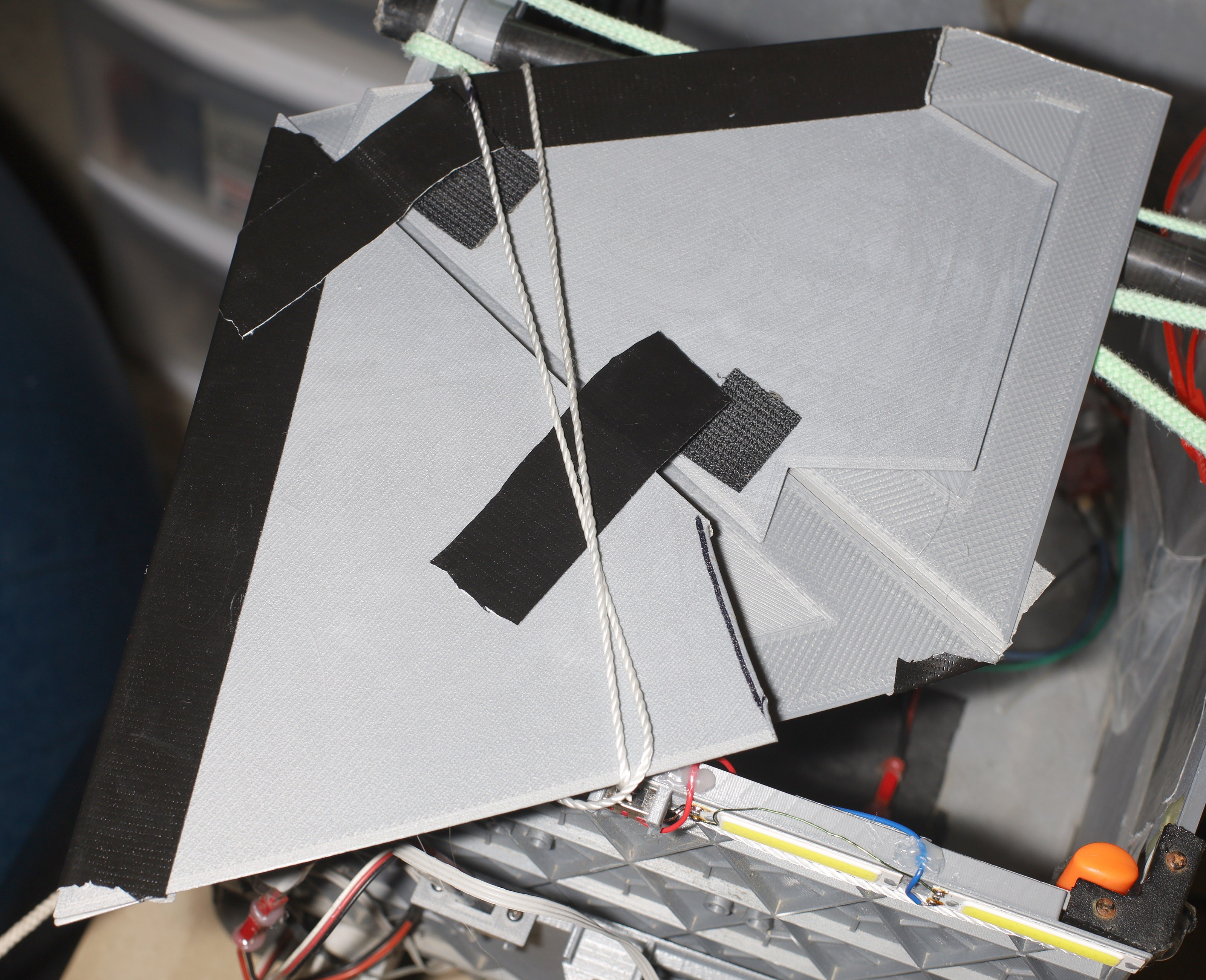
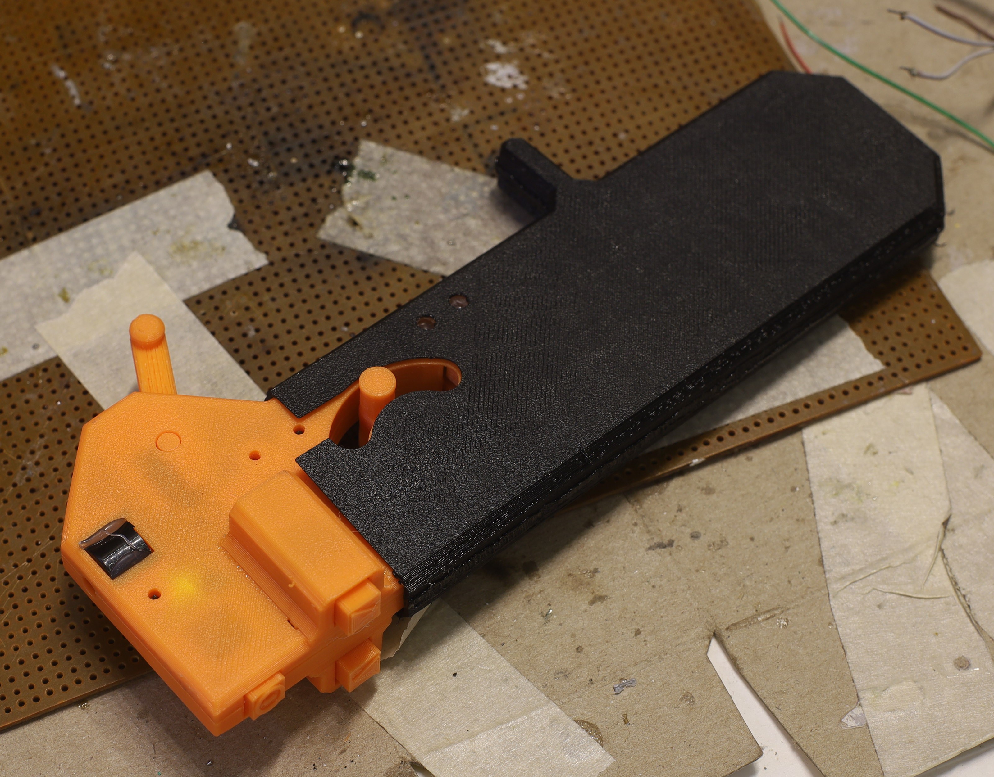
Another smashed steering panel from bashing into a curb resulted in another upgrade to the steering panel. No more glue required.
![]()
![]()
![]()
![]()
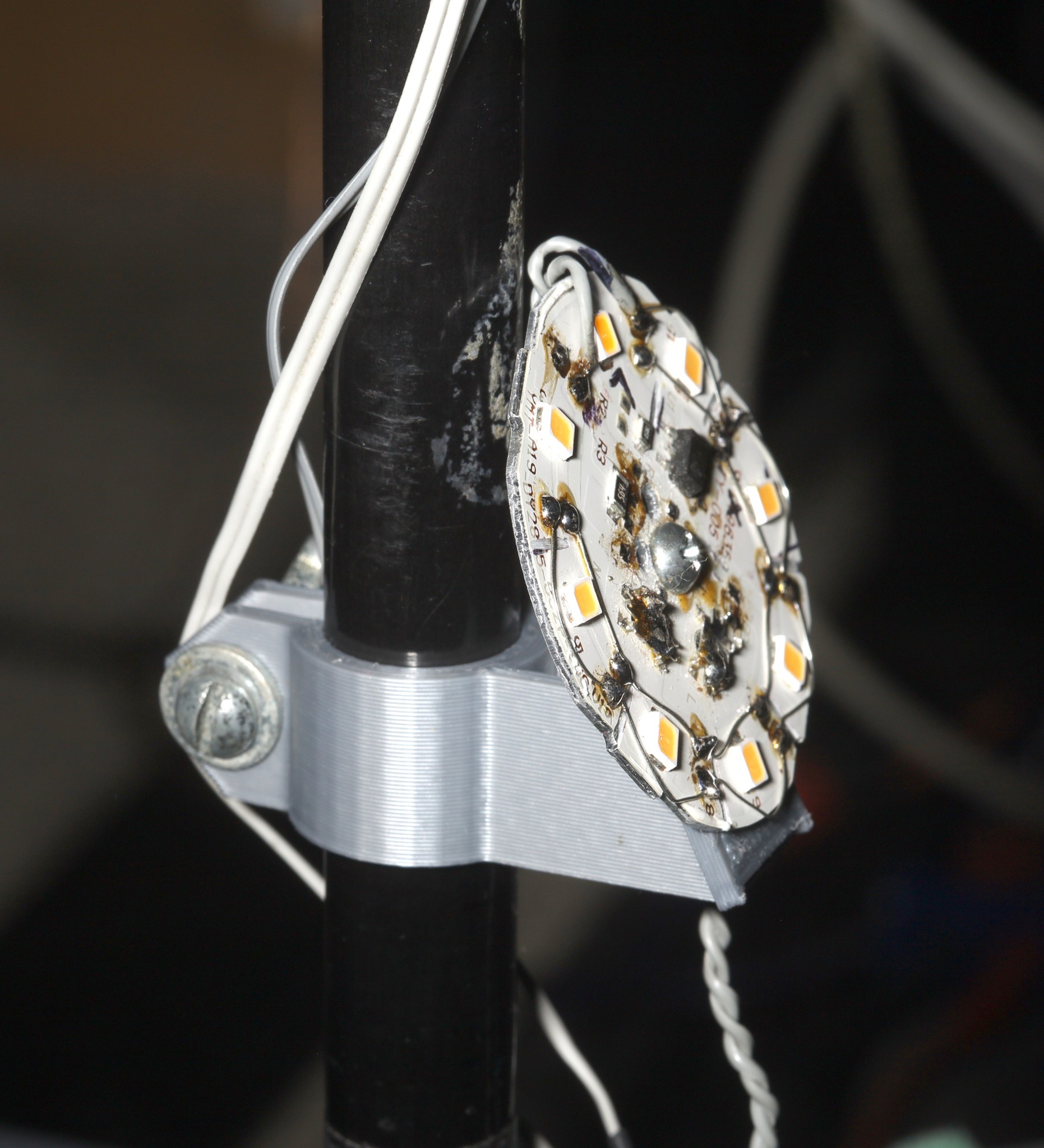
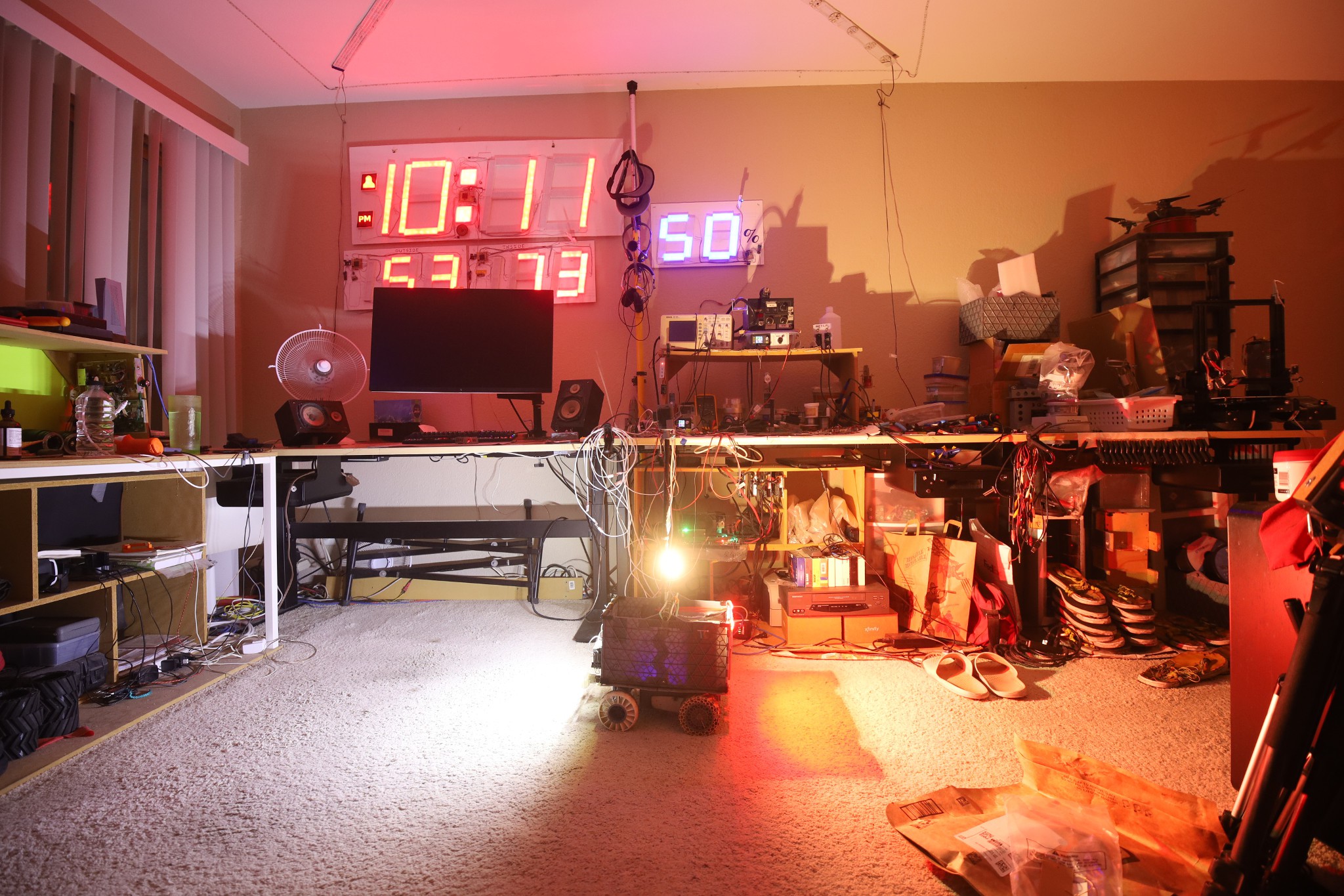
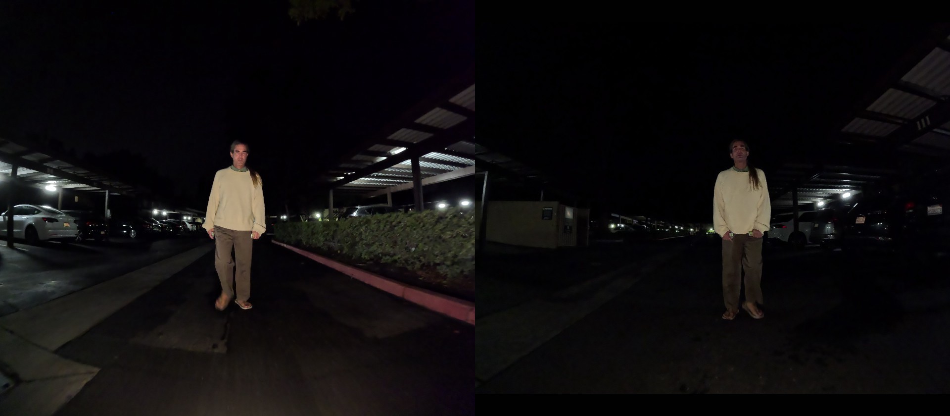
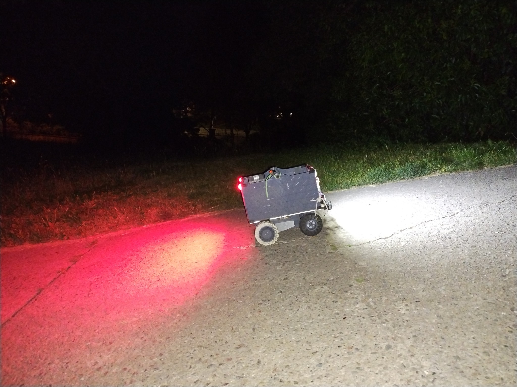
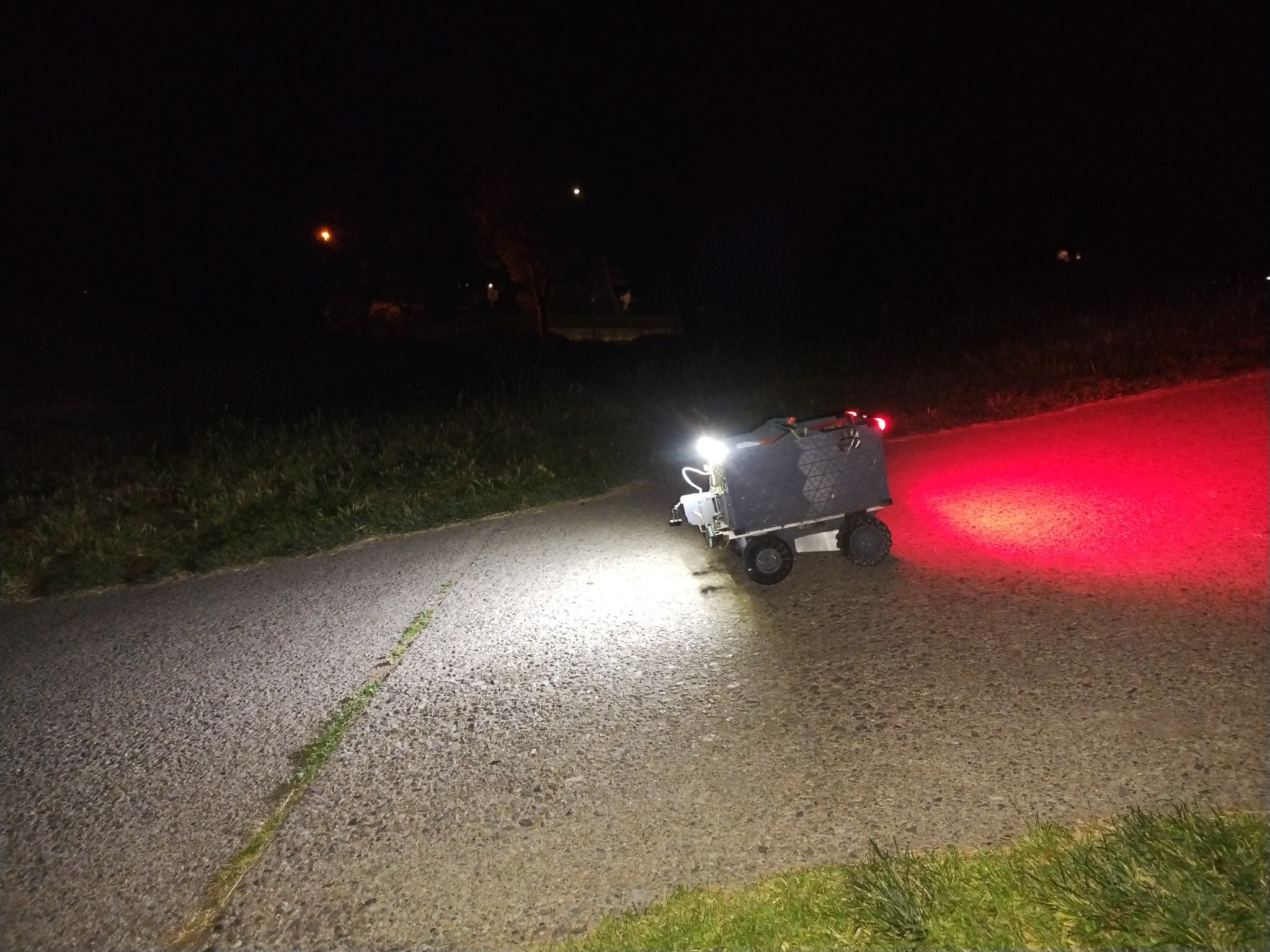
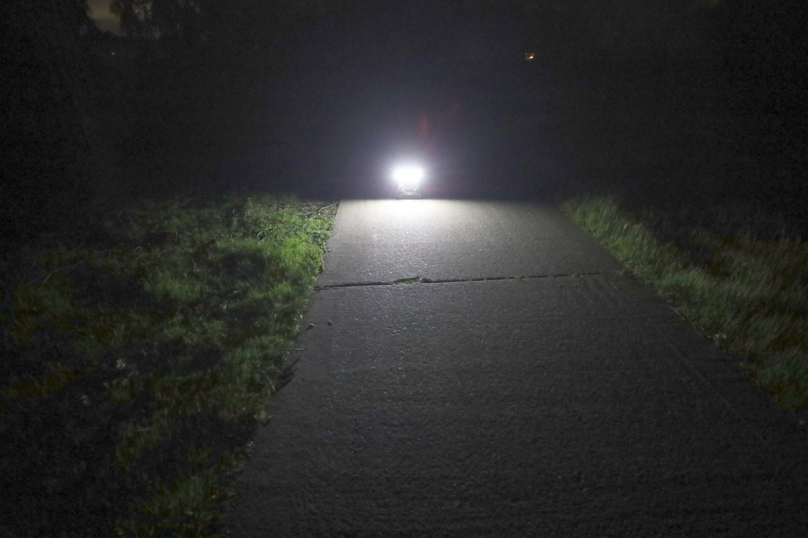
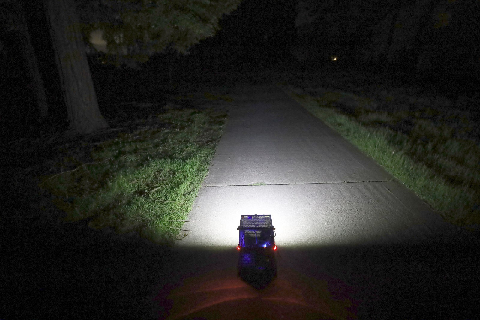
Camera pole got a new light which improved the rare night footage. Discovered gopro 24fps does better in the dark than the timelapse modes.
![]()
![]()
![]()
![]()
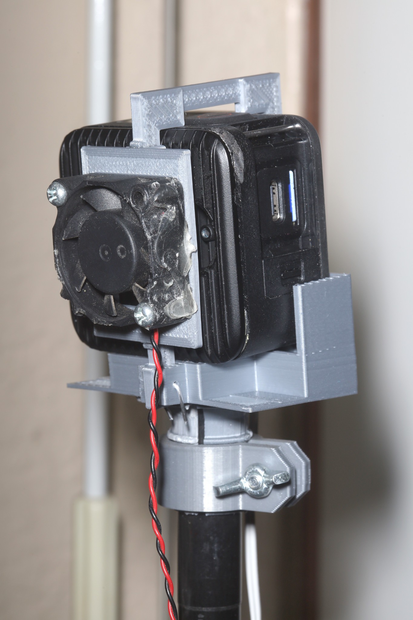
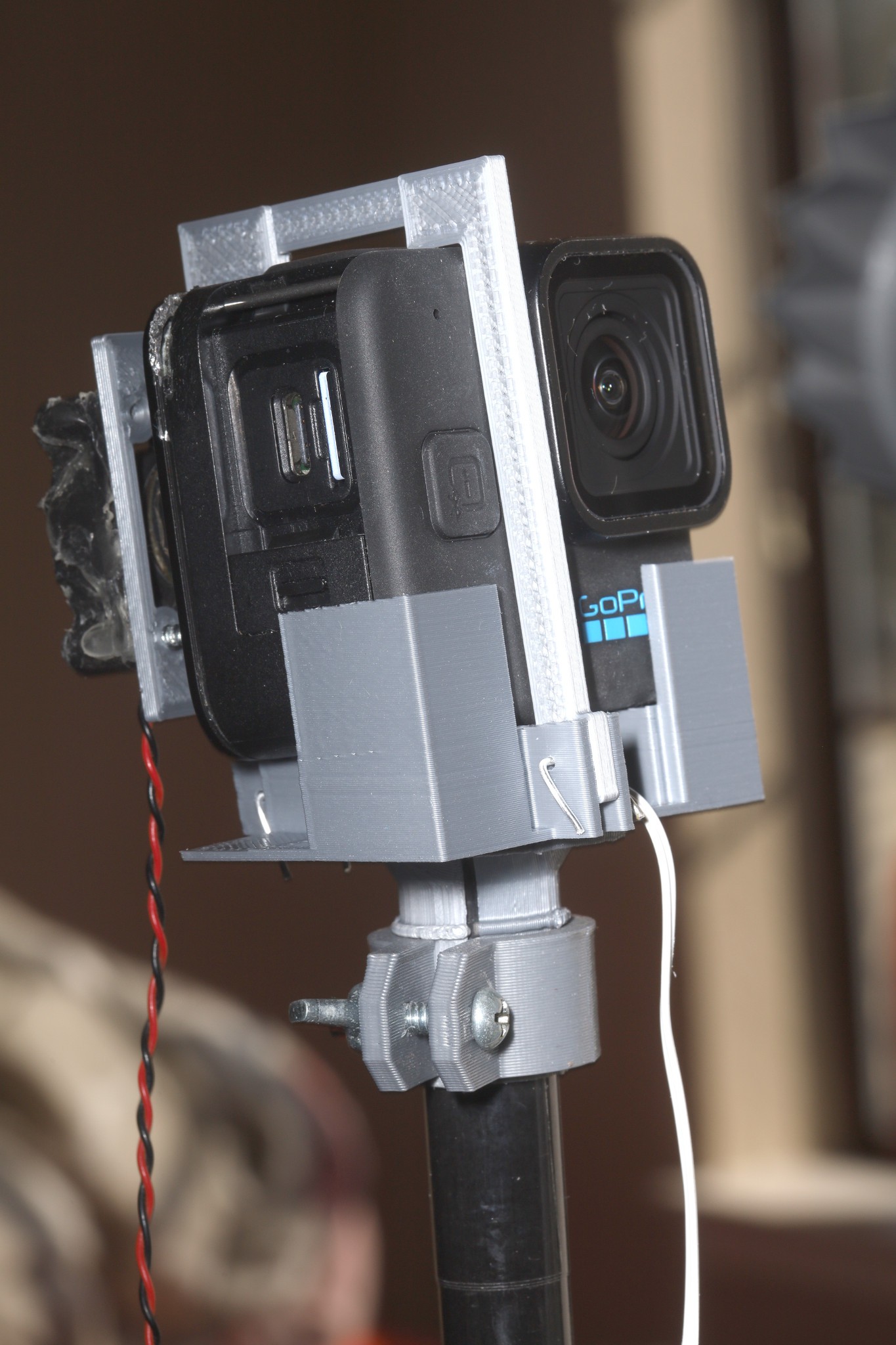
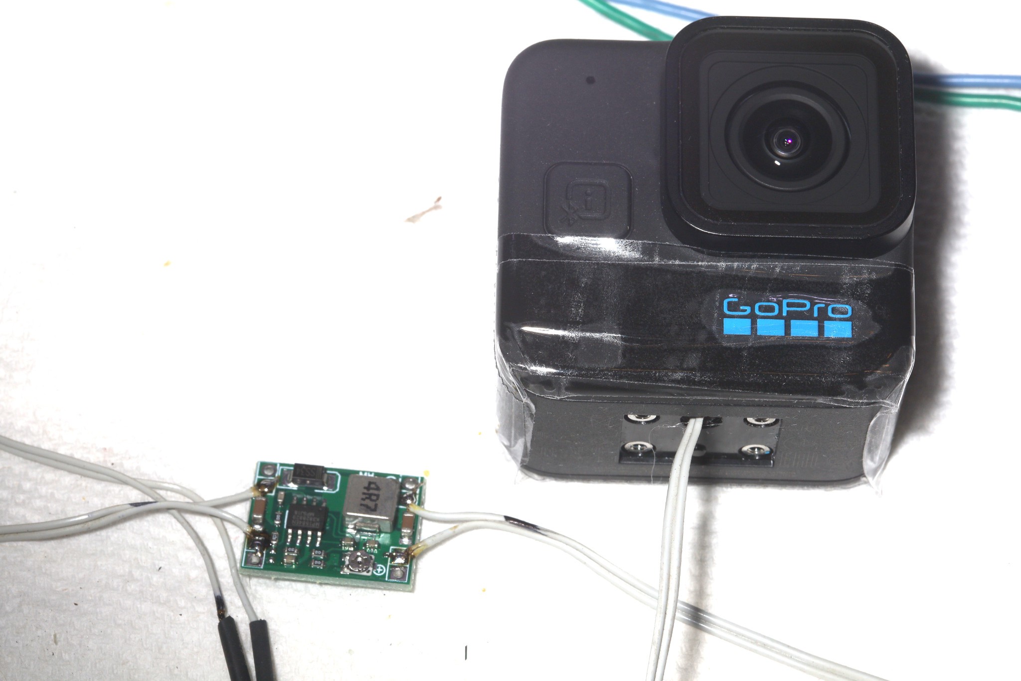
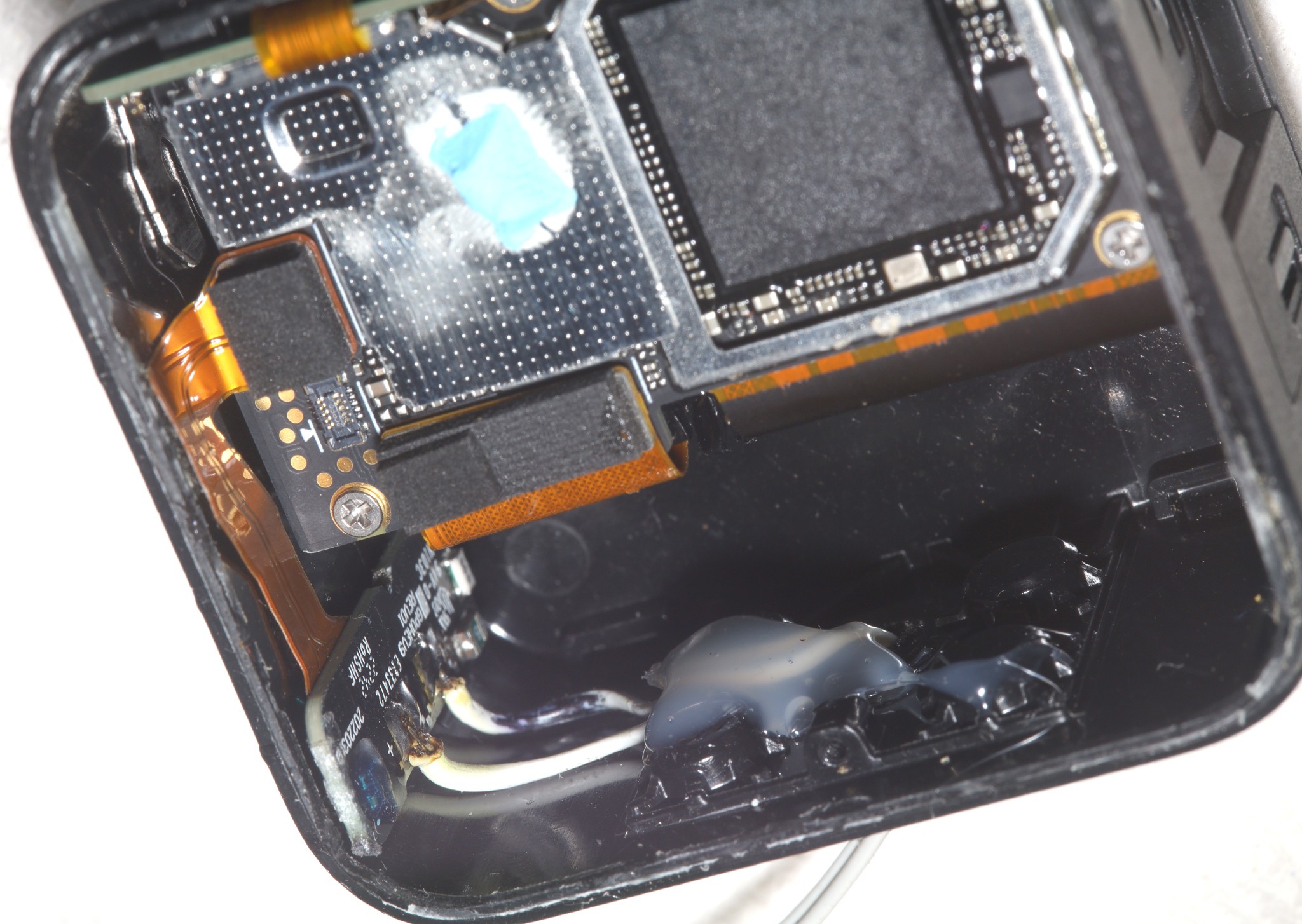
A lot of effort went into a gopro11 enclosure with active cooling & dummy battery.
The dummy battery required permanently breaking the heat sink off so it can never be used again without the enclosure.https://hackaday.io/project/203999-dummy-battery-for-gopro-11-mini
![]()
![]()
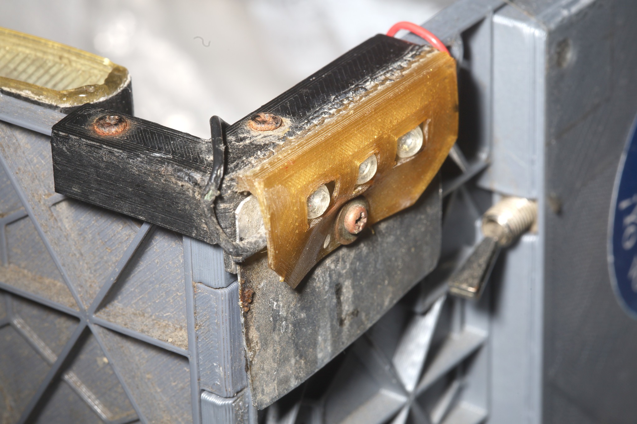
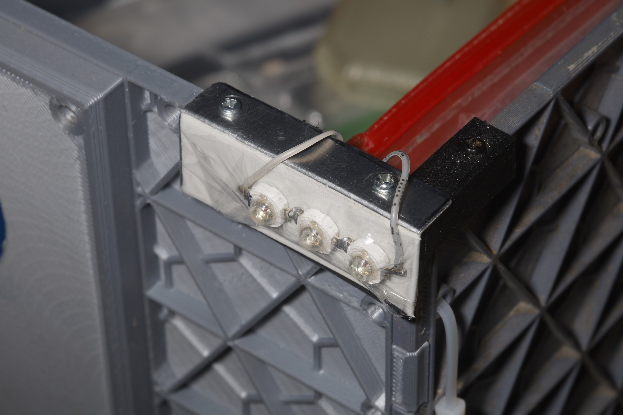
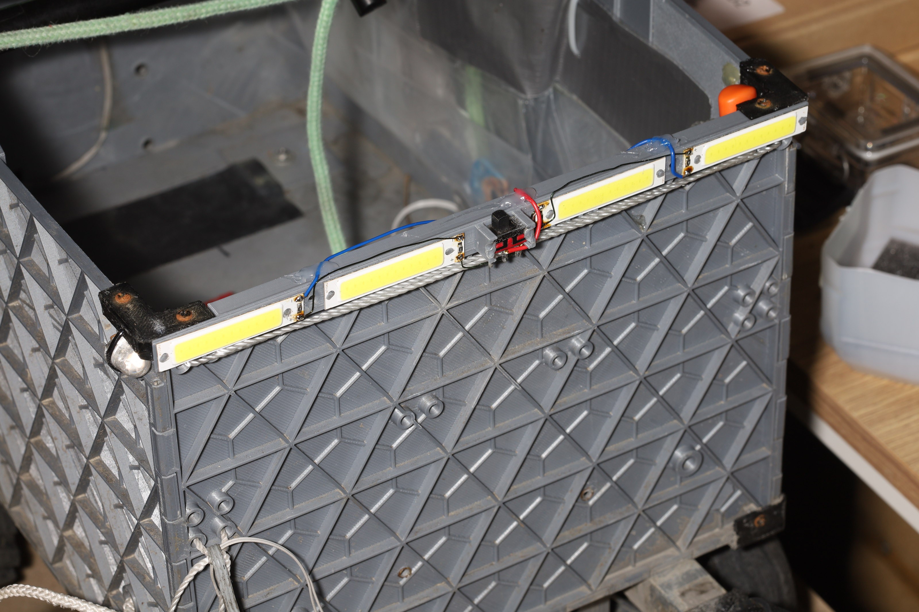
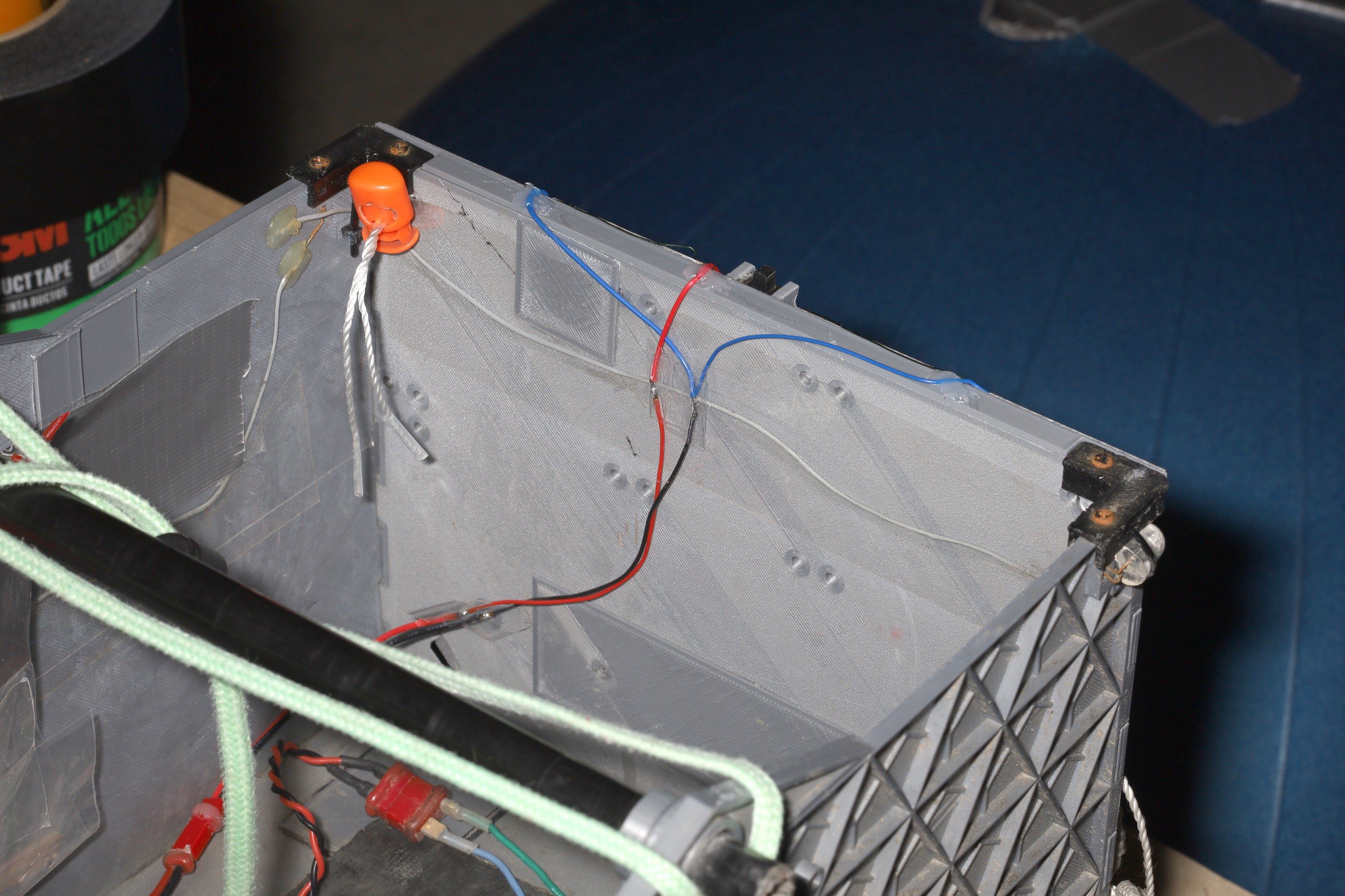
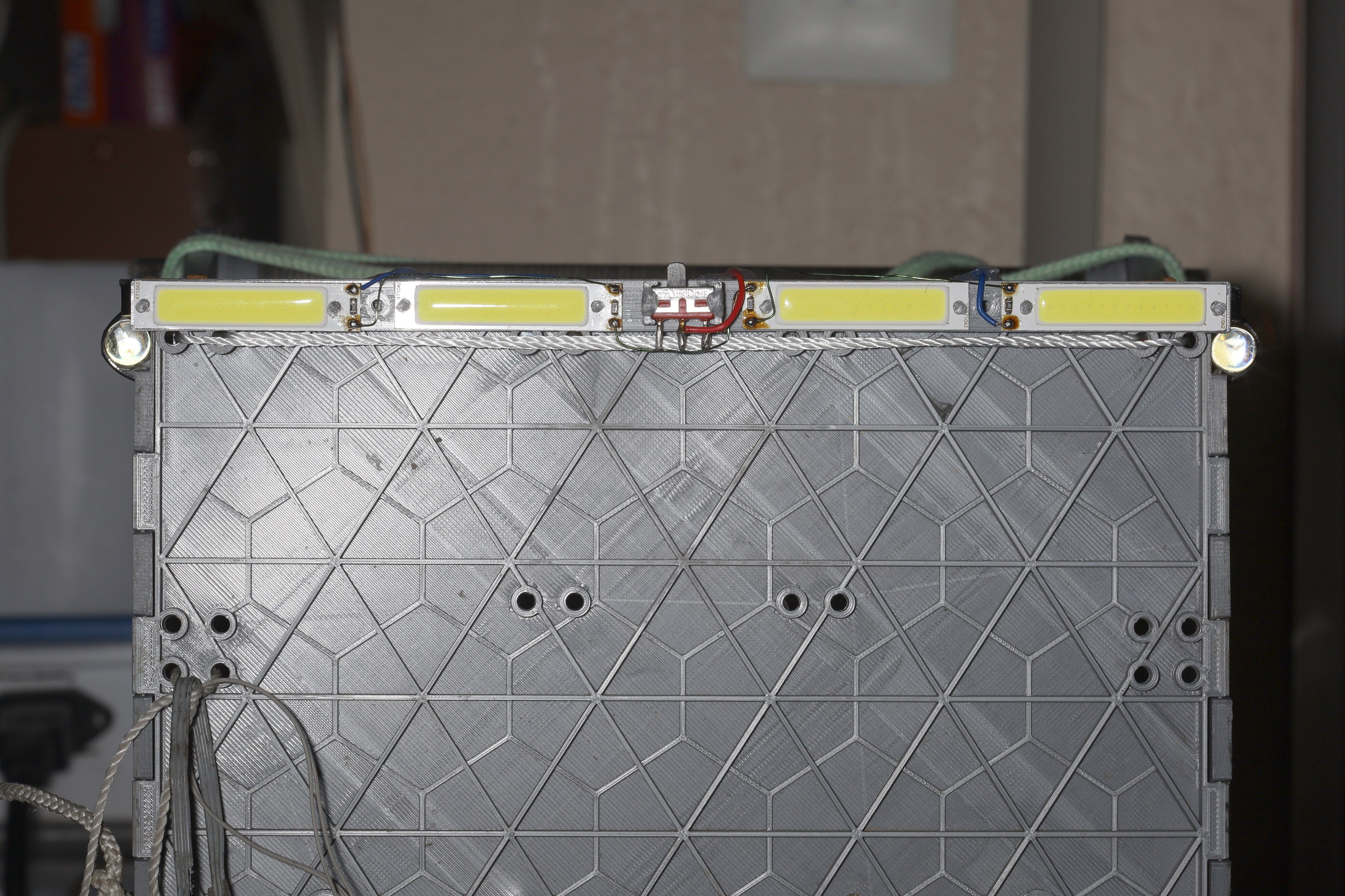
The well yellowed TPU tail lights were replaced by a new scotch wrapped aluminum angle, with stainless screws. The new problem is the scotch trapping dirt between the LEDs & adhesive tape, but the contact is about as bad as the TPU. This is going to be a wear item.
![]()
![]()
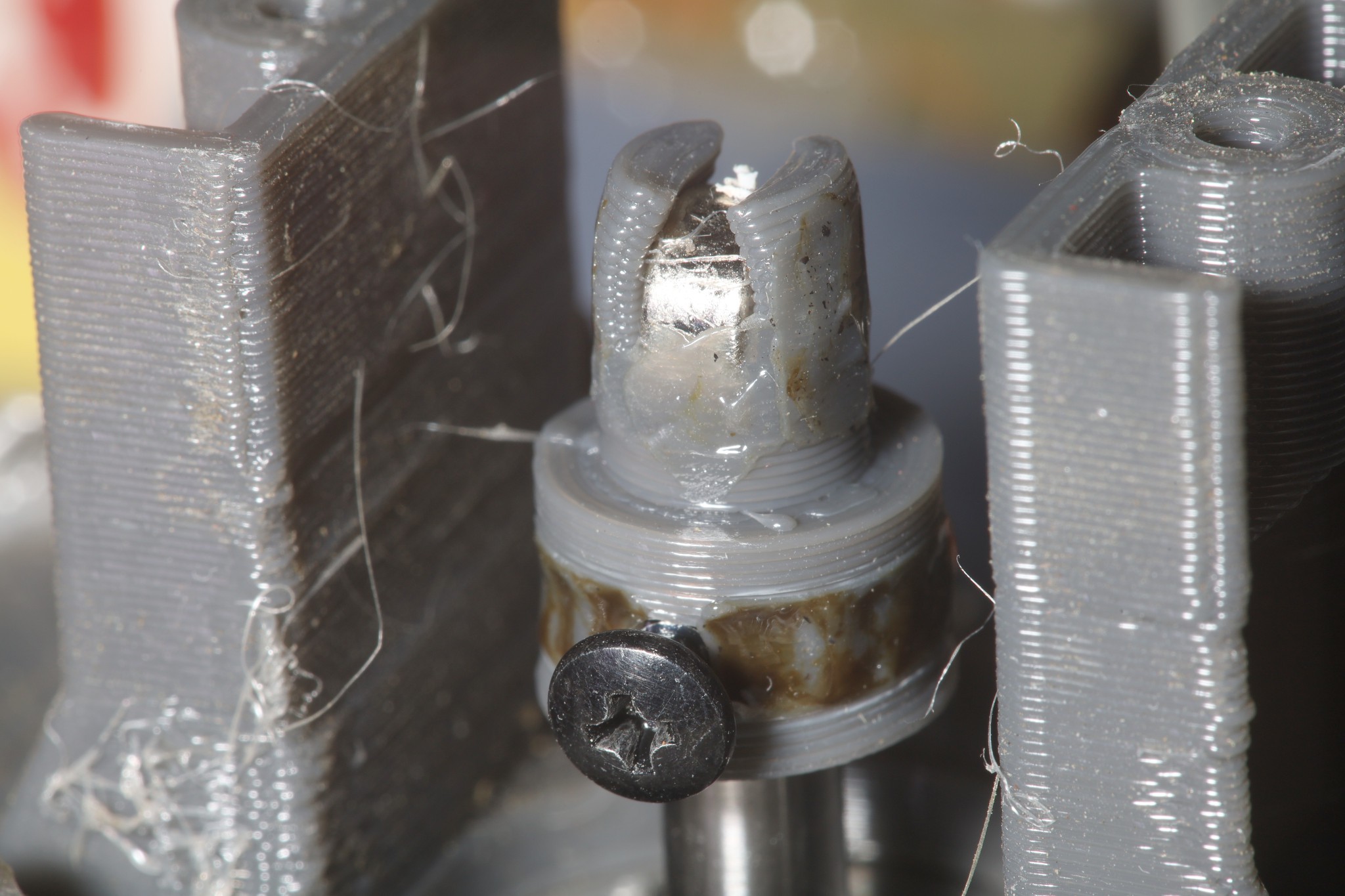
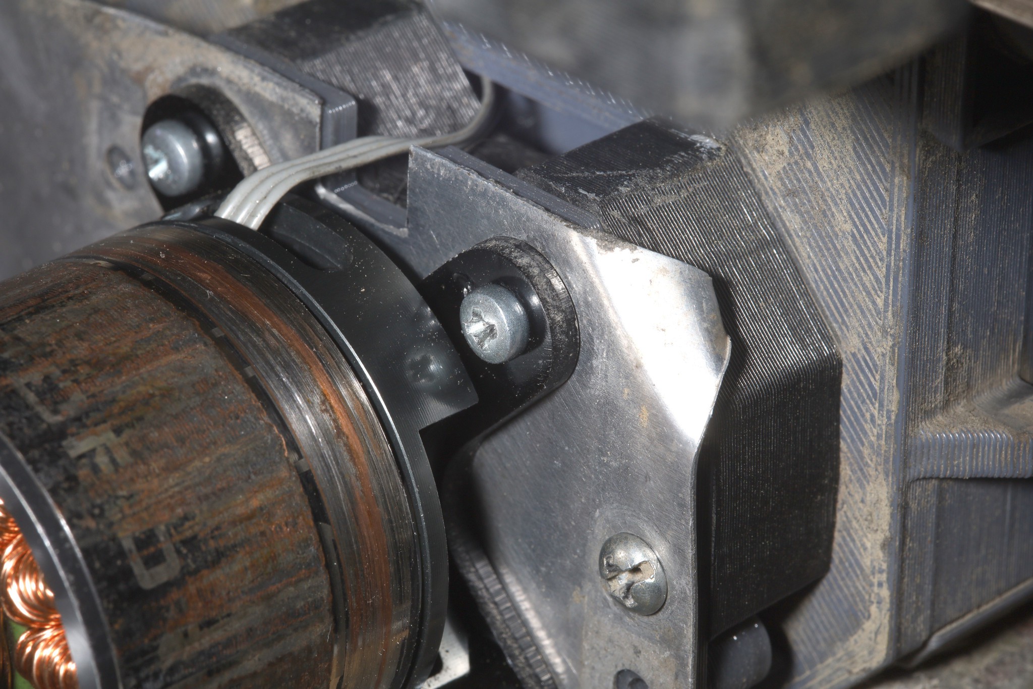
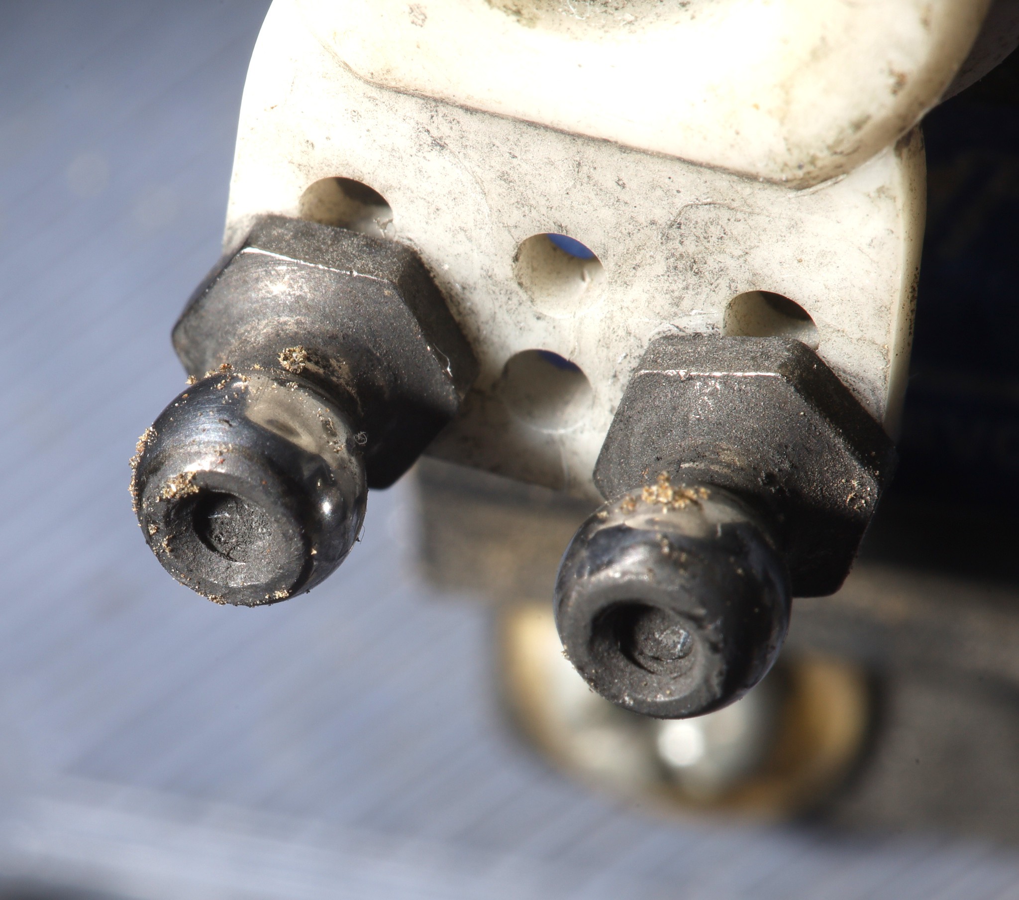
A protracted battle with the motors seizing resulted in a new magnet holder & farsteners upgraded from 2-56 to M3. The tiny fraction of a mm seemed to fix the seizing, but the real problem is depending on an encoder which is aligned by a load bearing structure. Studies into Clarke & Park transforms showed there's still no way to time the commutations at low speed without a dedicated encoder. A gear driven encoder would be the next step, but would suffer from different types of errors.
The firmware got a new feature which allows a seized motor to be deactivated. That way it can drive on just 1 motor or be pulled in leash mode by an animal.
![]()
![]()
![]()
![]()
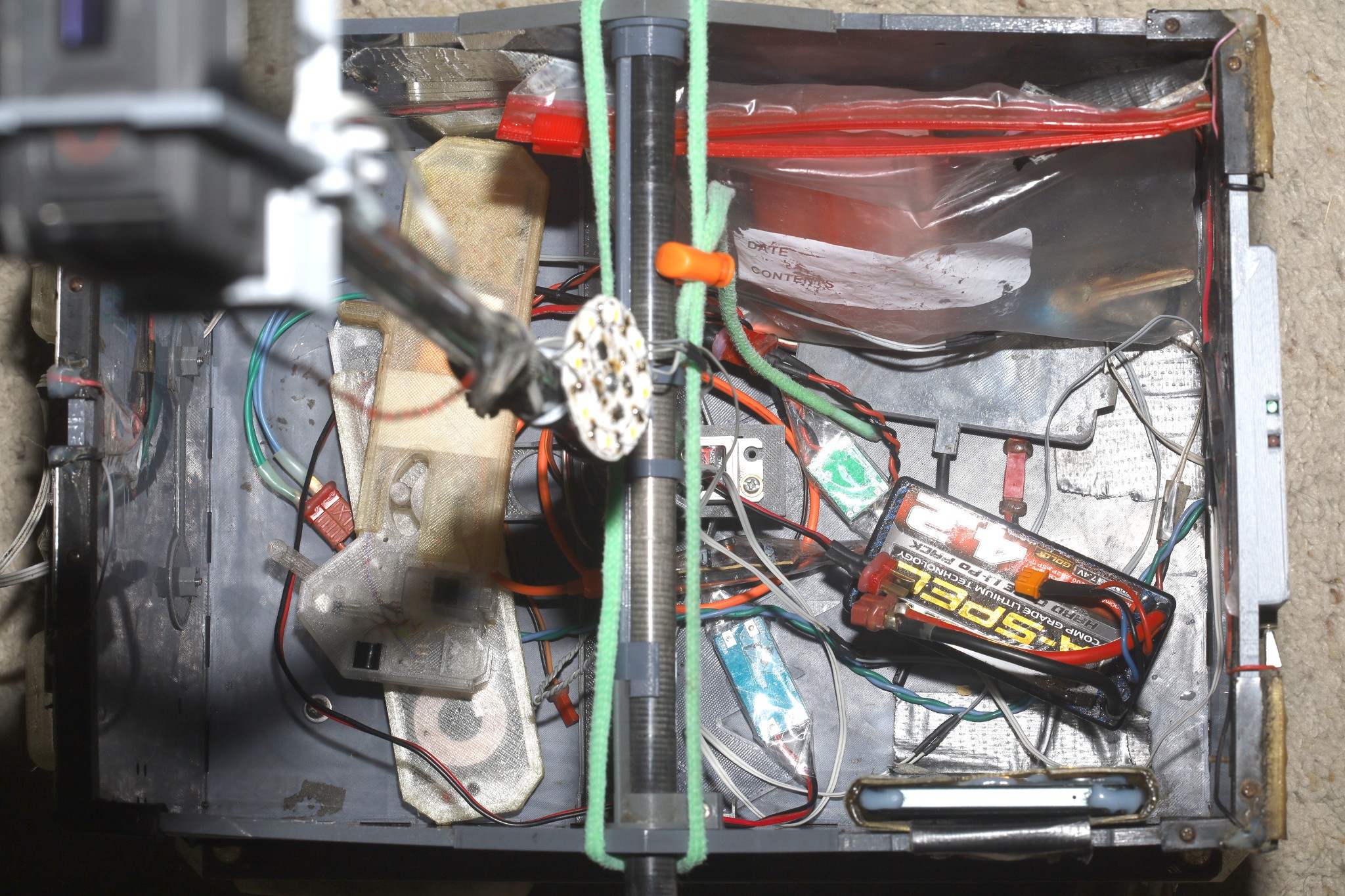
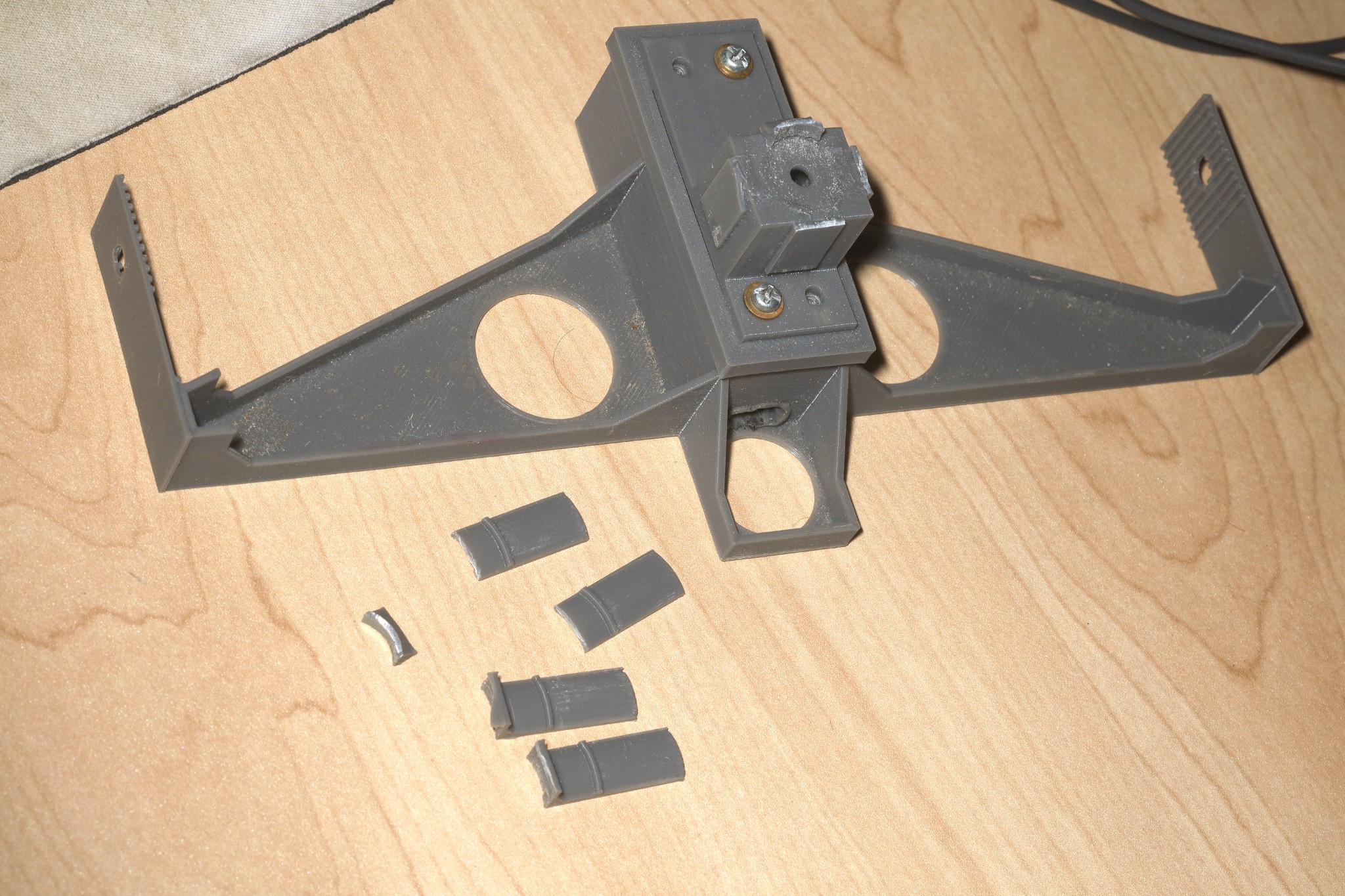
More breaks in the dummy servo resulted in another adapter, which once again requires the camera pole to be removed to access the dummy servo.
![]()
Then it got further refinement to try to reduce the mangling of food.
![]()
![]()
![]()
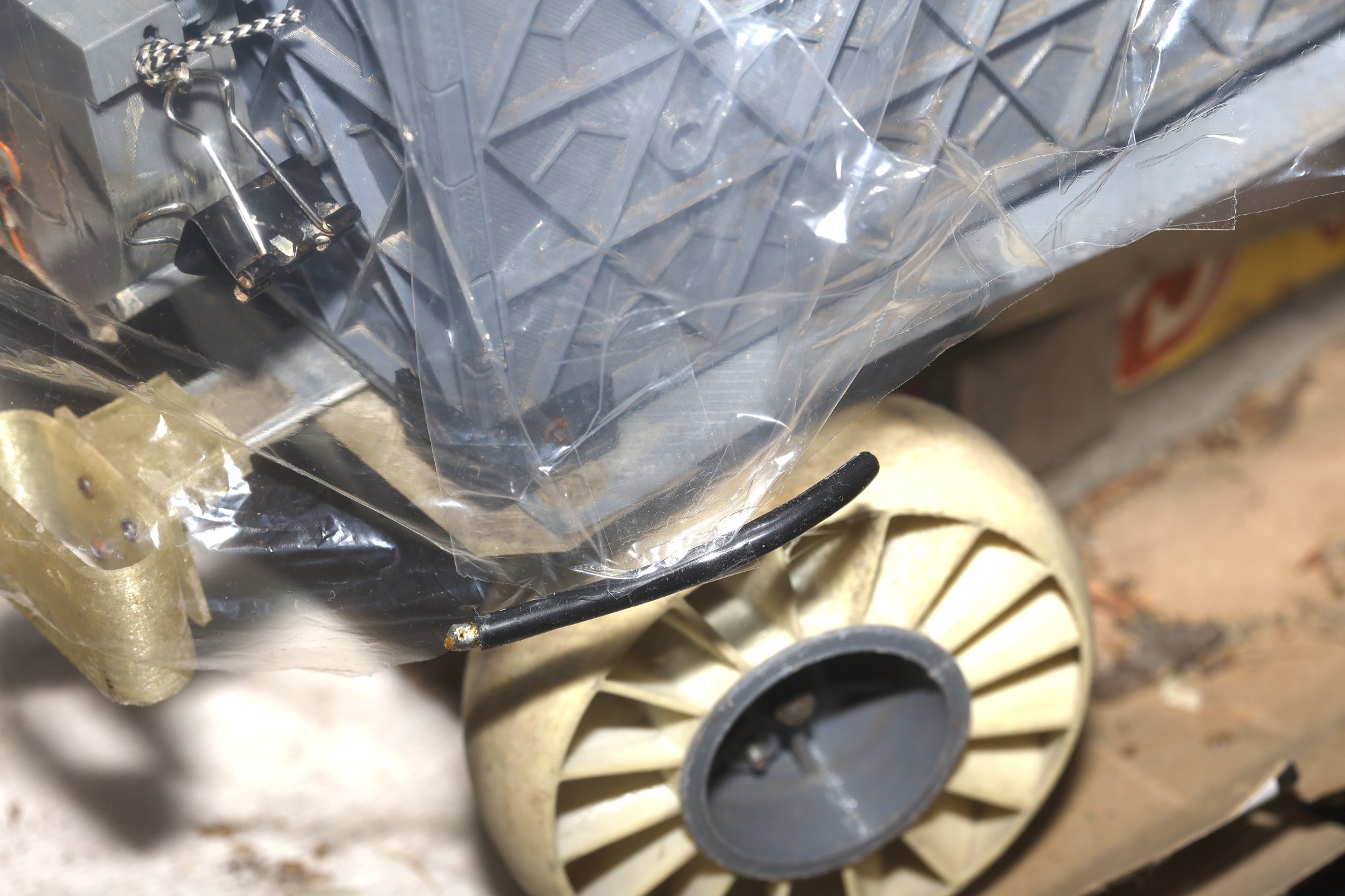
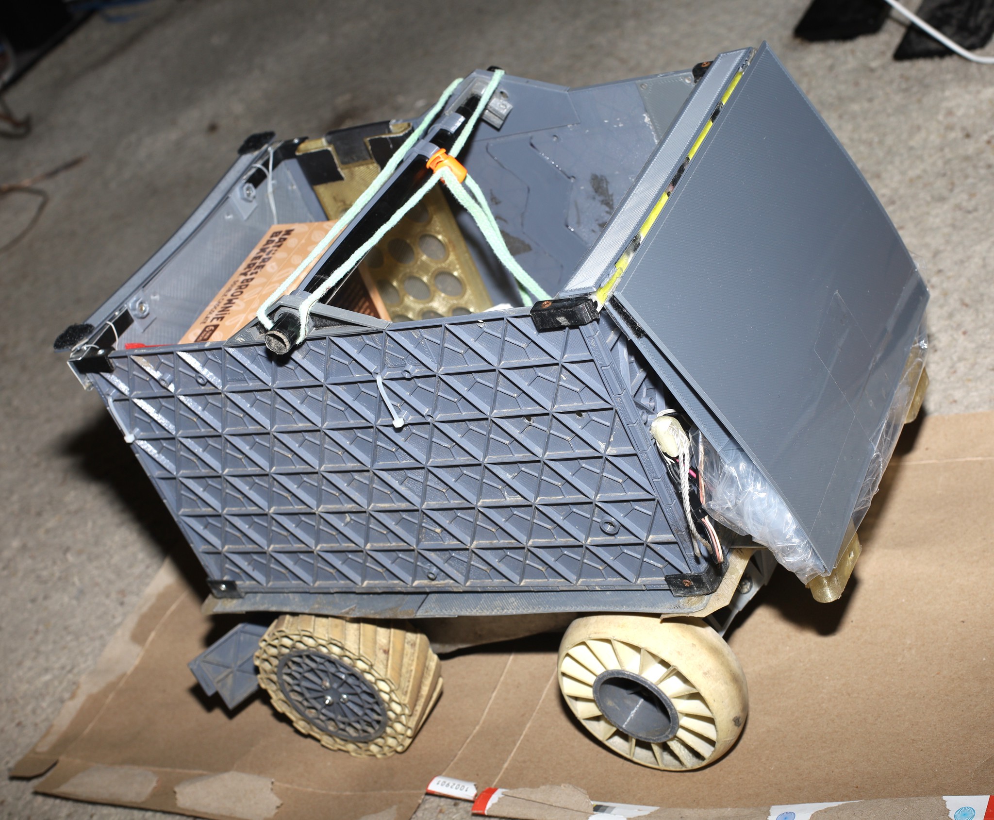
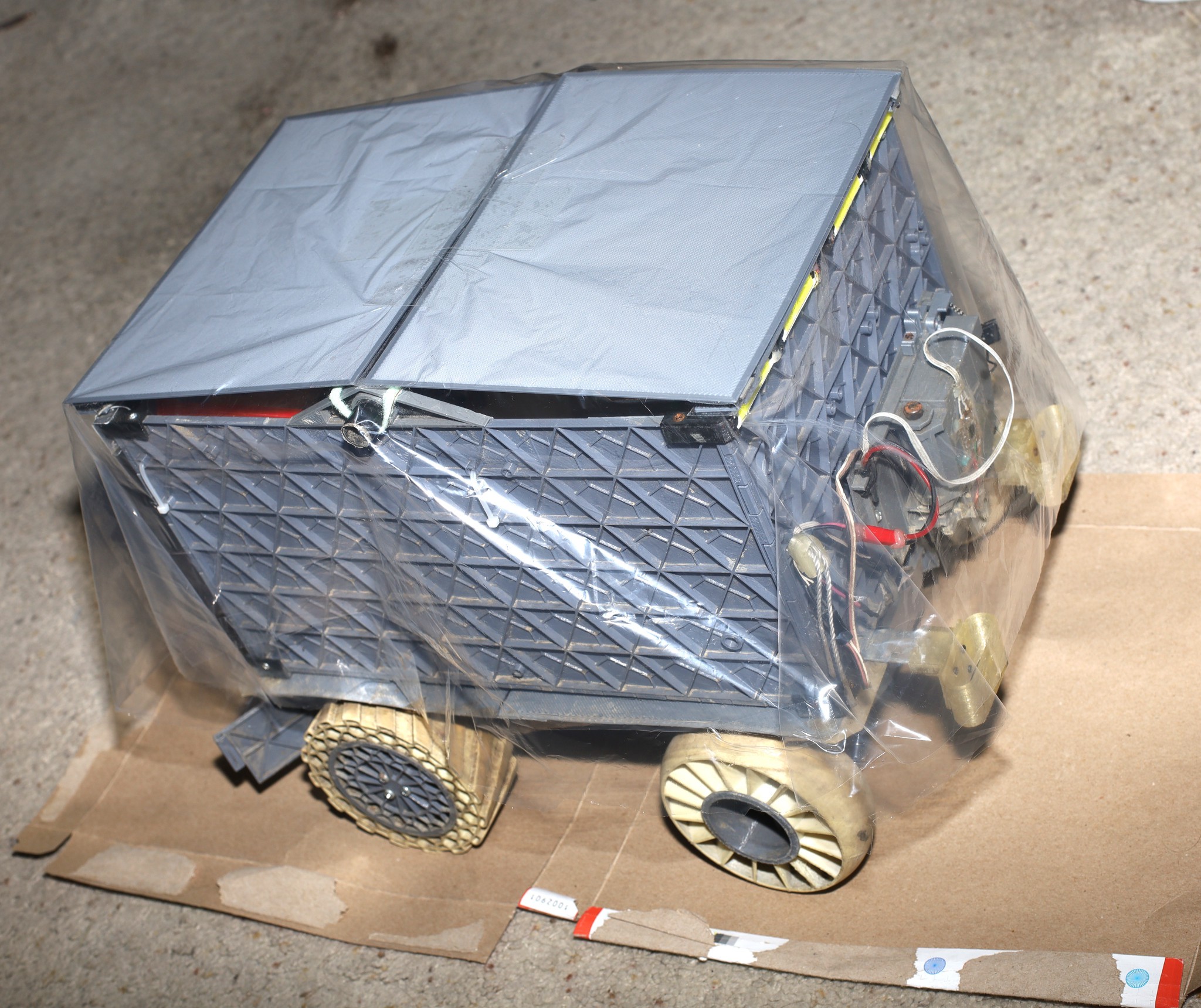
Efforts at waterproofing had little success. The latest idea was an elaborate combination of PLA panels, velcro, & recycled poncho plastic which completely covered it. This was quite cumbersome, bulky, & prone to getting blown away.
![]()
![]()
![]()
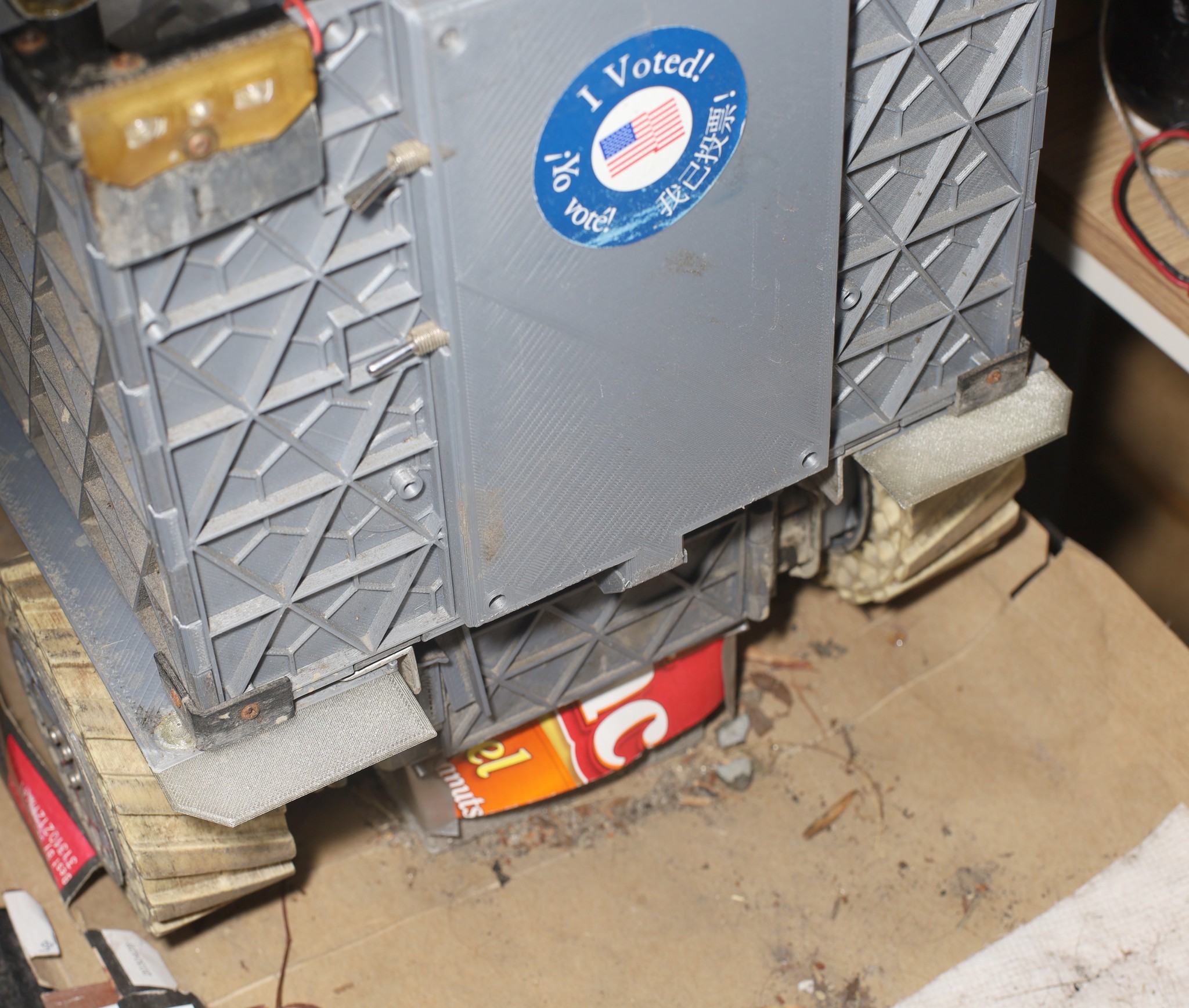
Ongoing efforts with splash boards were keeping the container relatively clean, but not very dry. The mane problem has been keeping them from getting smashed during backflips & side swipes. They've been trending towards a pure TPU construction.
-
New transmitter
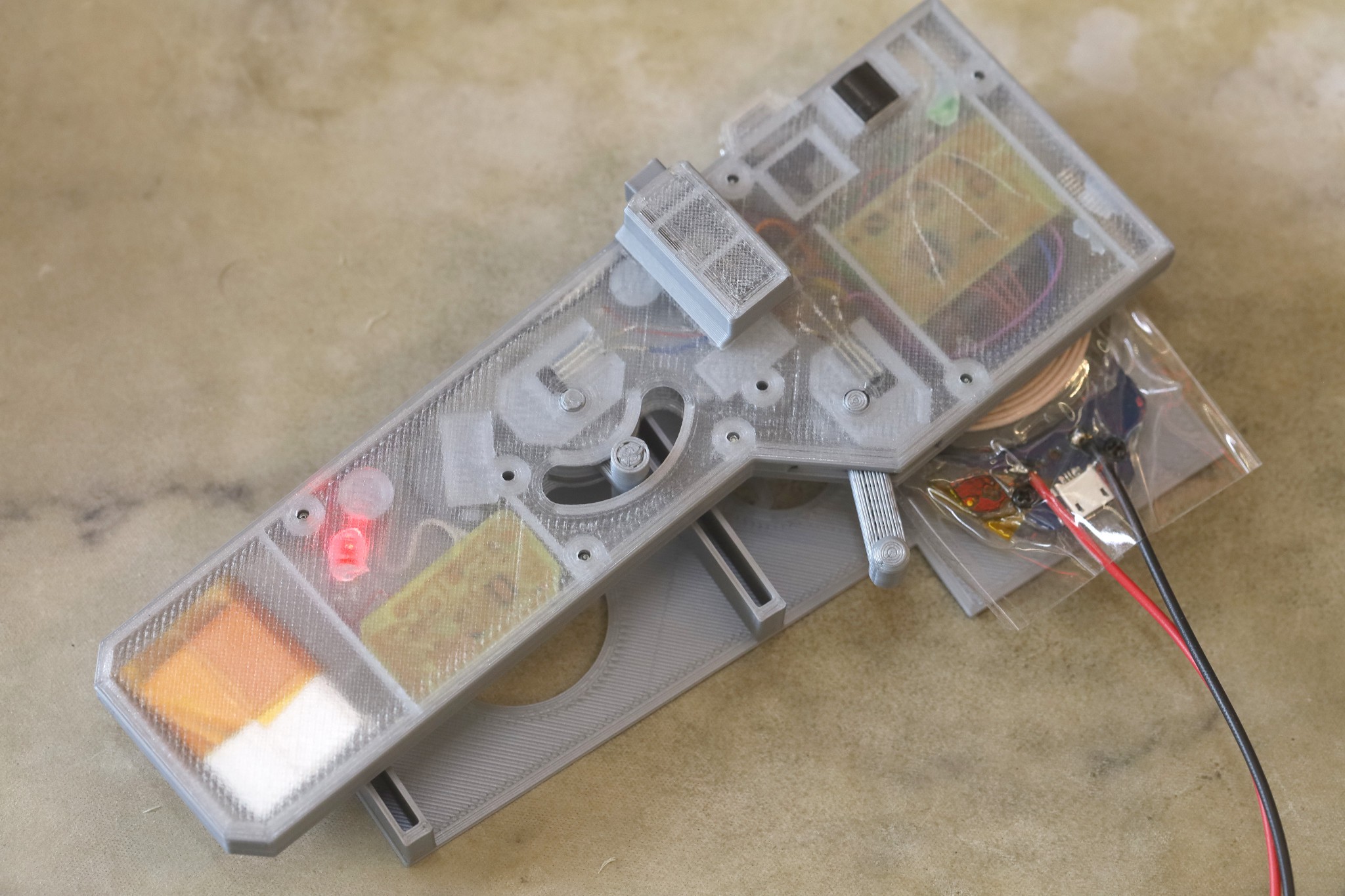
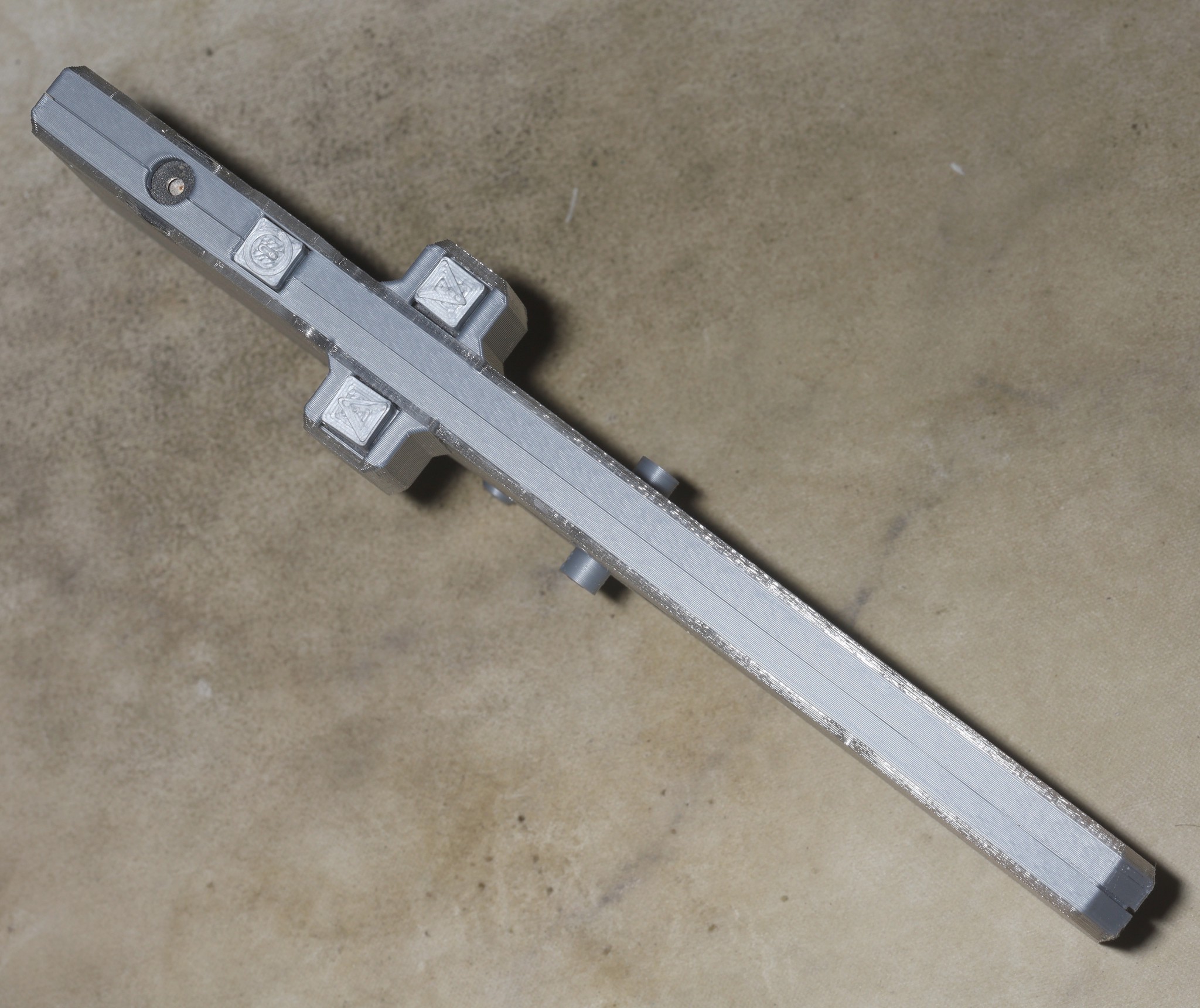
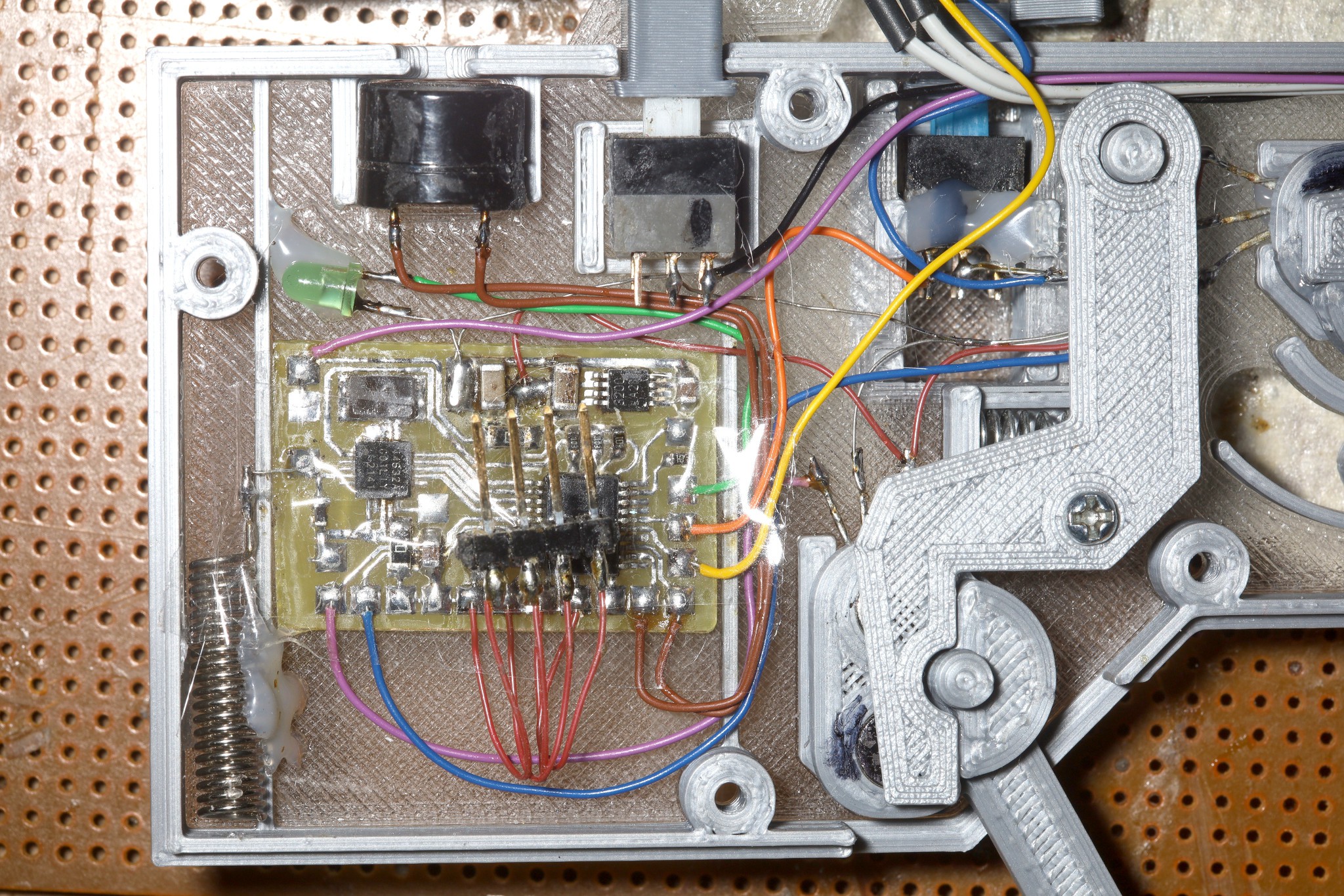
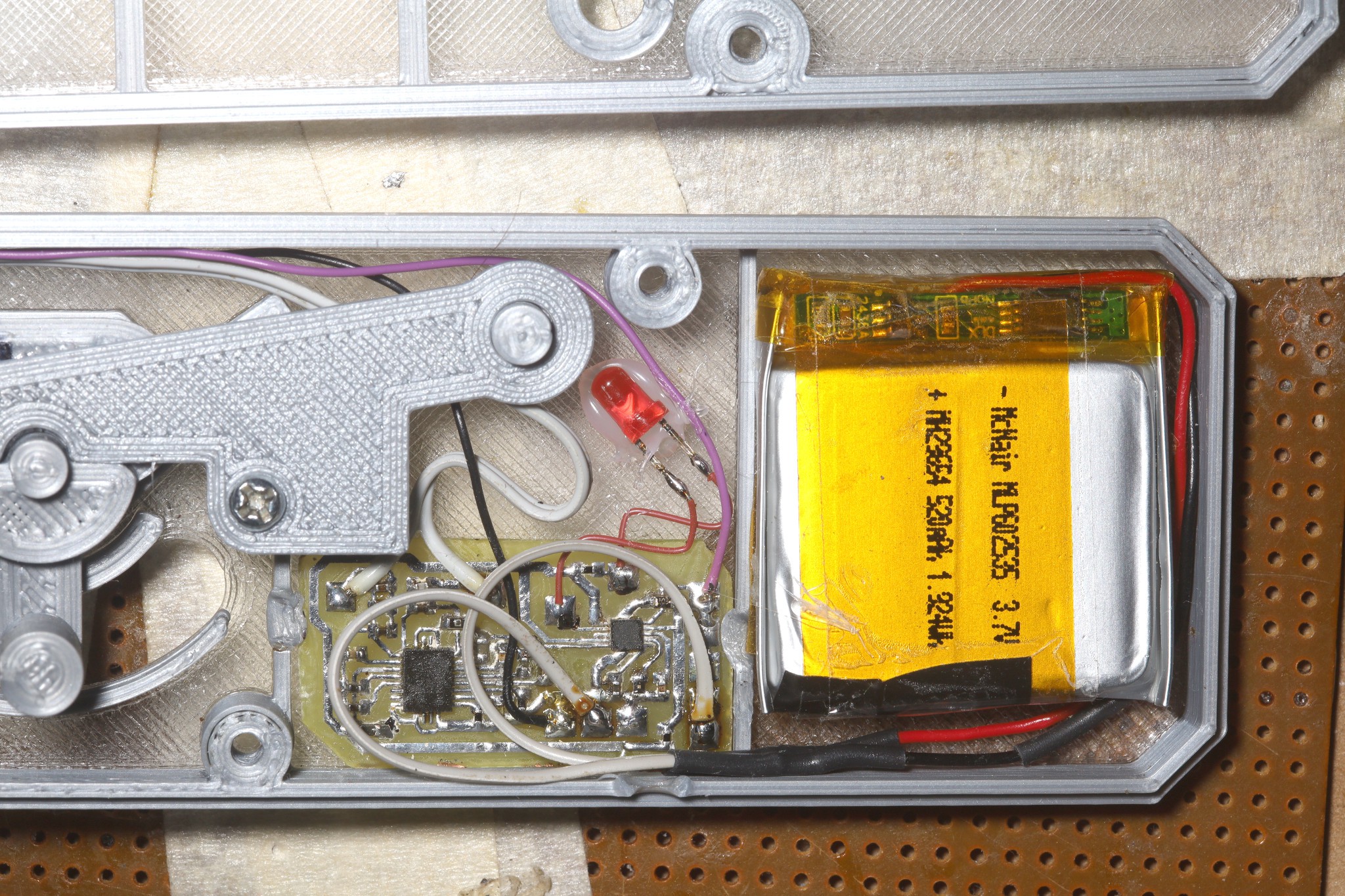
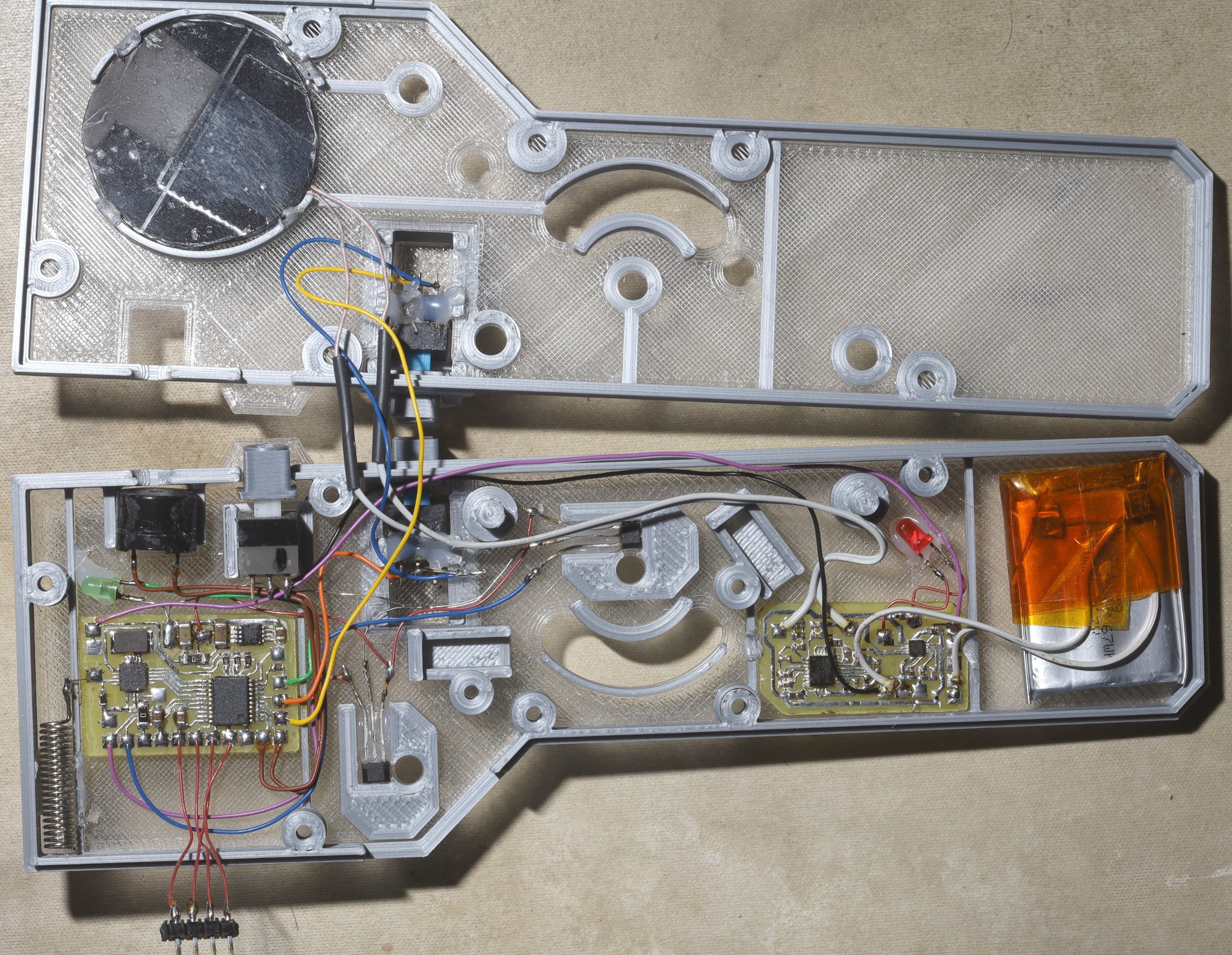
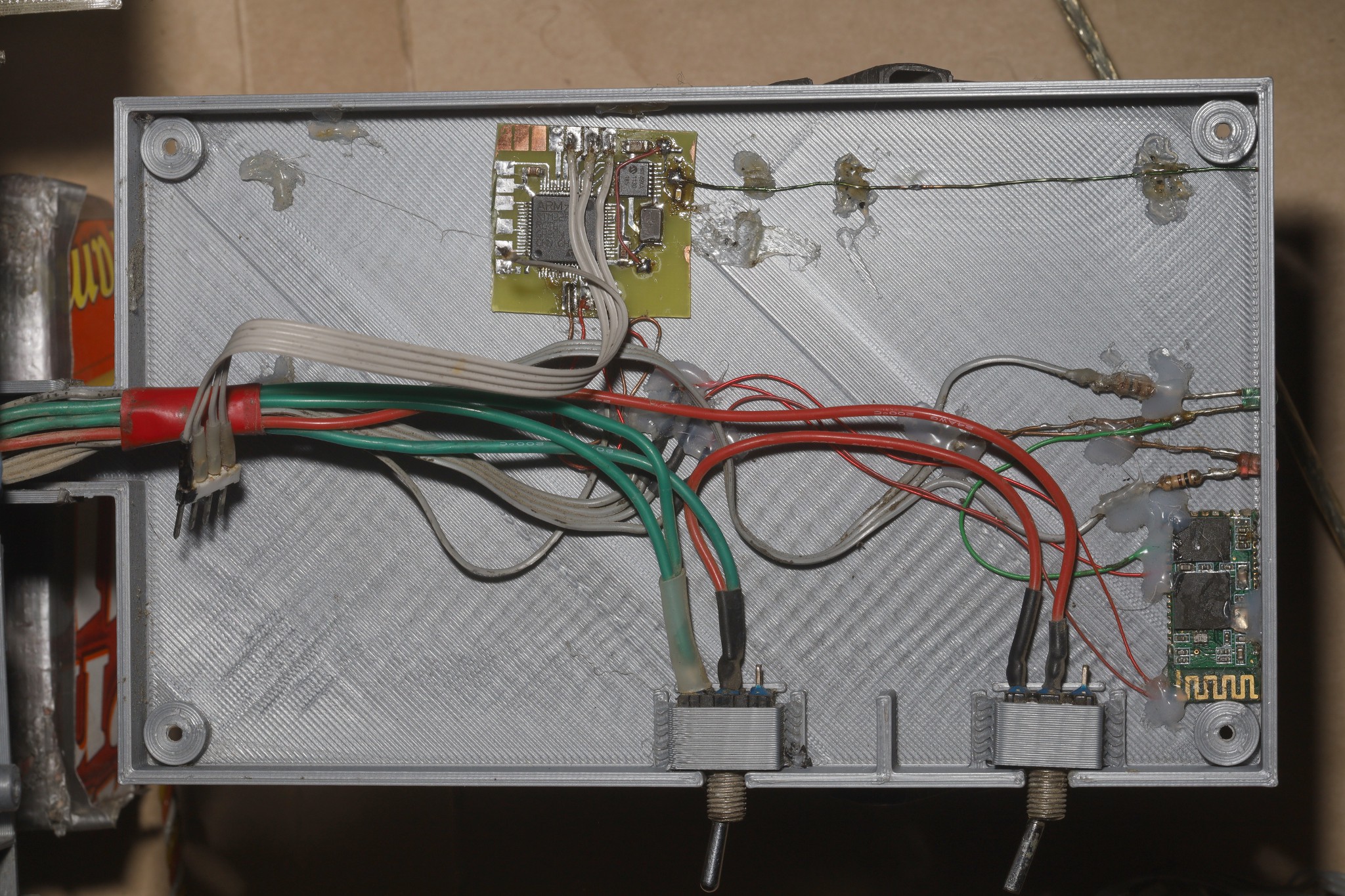
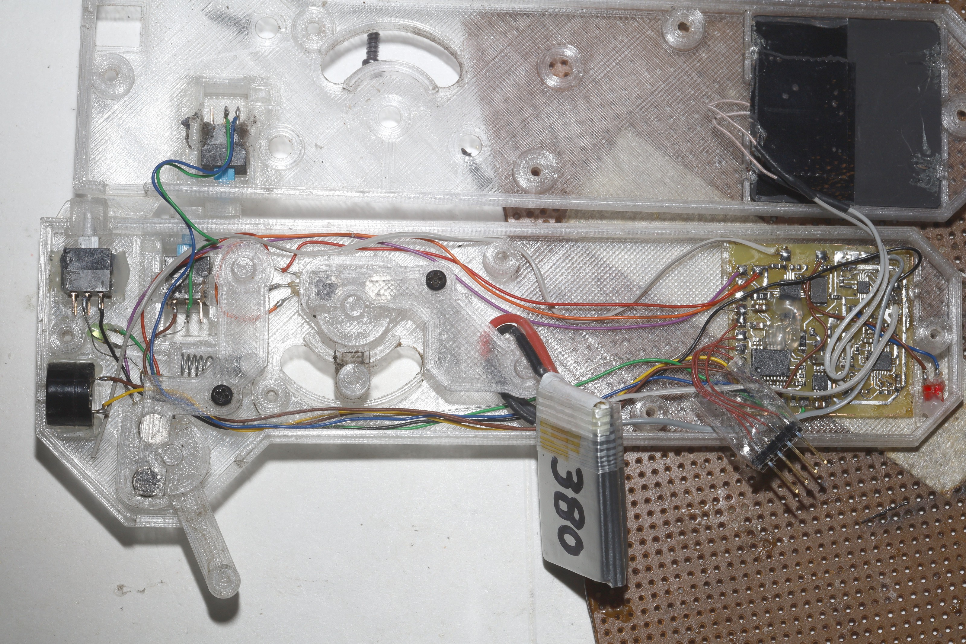
06/11/2026 at 06:36 • 0 commentsBesides upgraded motor assemblies, waterproofing structures, steering structures, tail lights, camera mounts, the big improvement since 2024 was a new transmitter & radio set. The radios changed from raw RS232 to PWM. Time differences between level transitions determined a 1 or 0. The bitrate was reduced from 100kbit to 25kbit. A new transmitter & charger were made, with more antenna exposure, more room for a bigger battery, more audible speaker position.
![]()
![]()
![]()
![]()
![]()
![]()
![]()
![]()
![]()
![]()
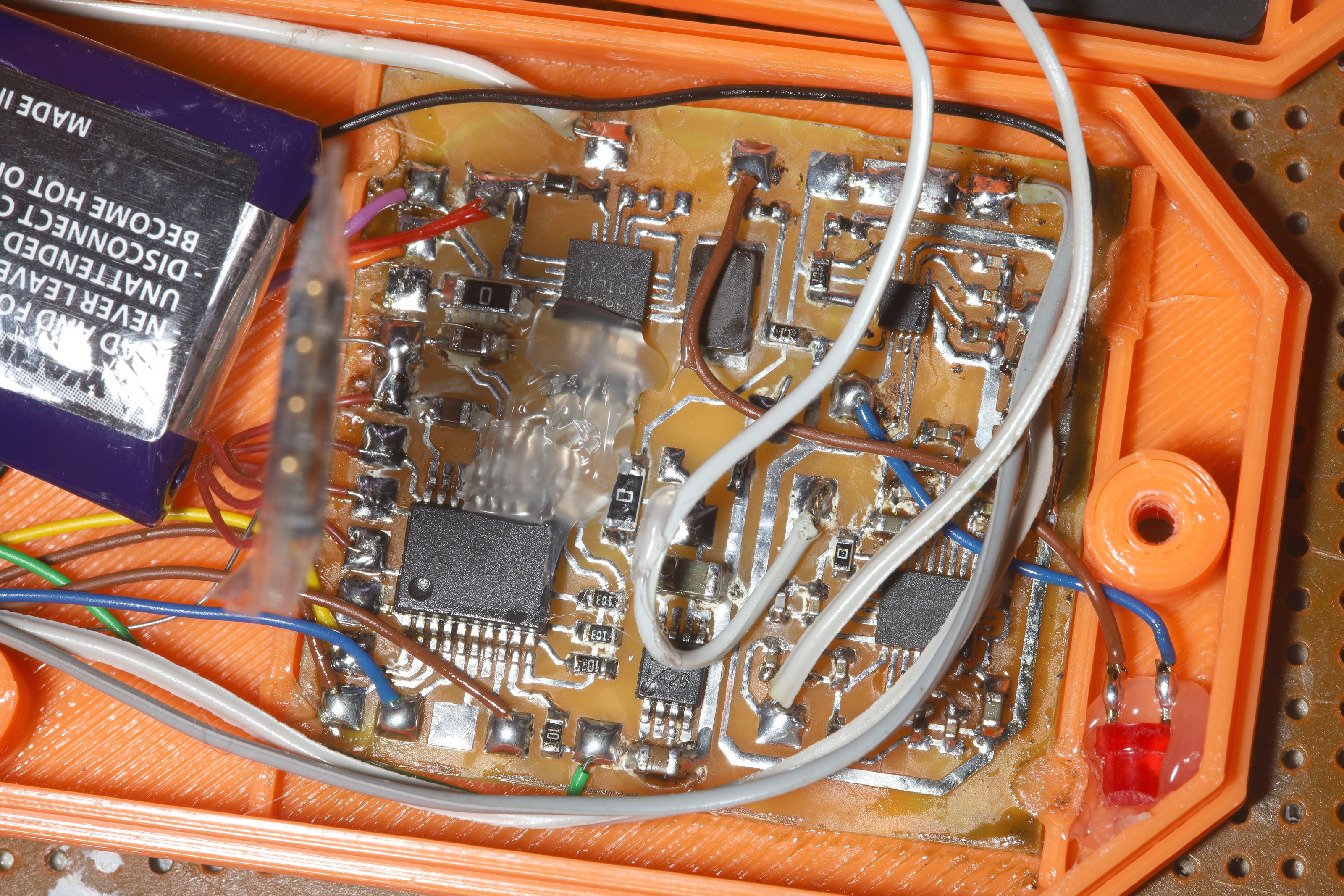
Split the circuit into a charger board & radio board.
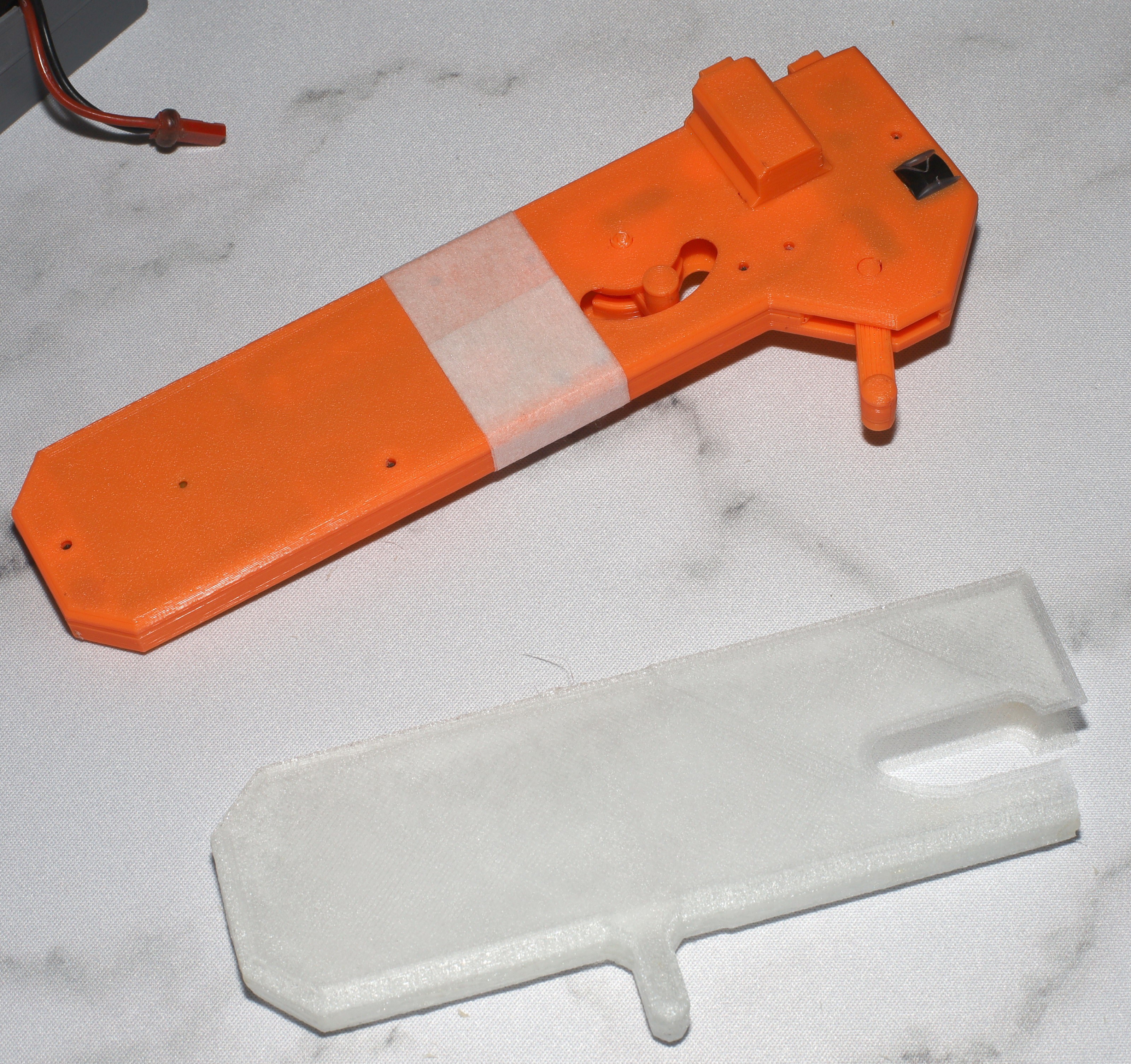
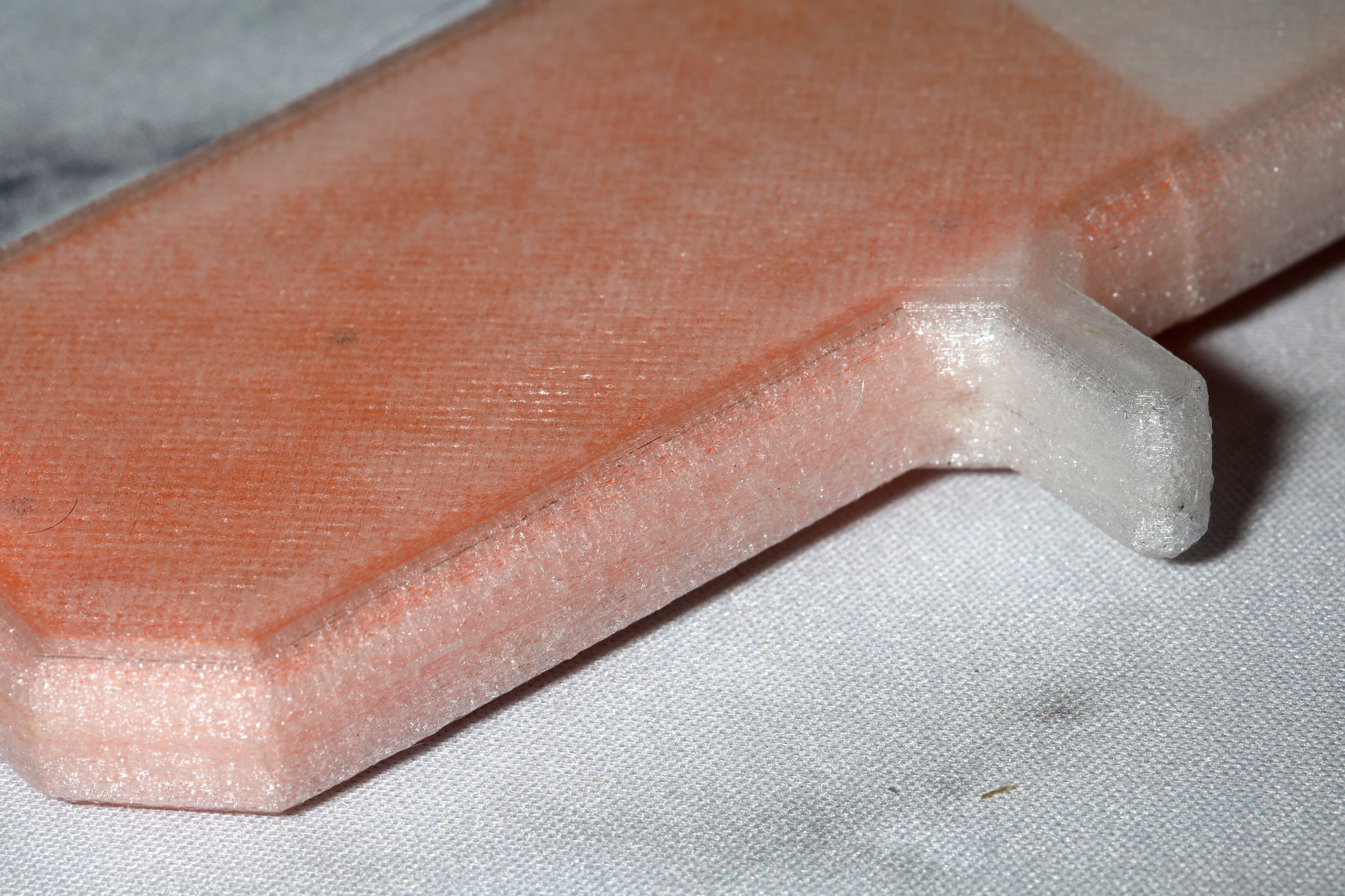
A mix of clear & grey filament made an appealing case, but any future clear PLA was abandoned. It lead to overheating in sunlight & was too brittle.
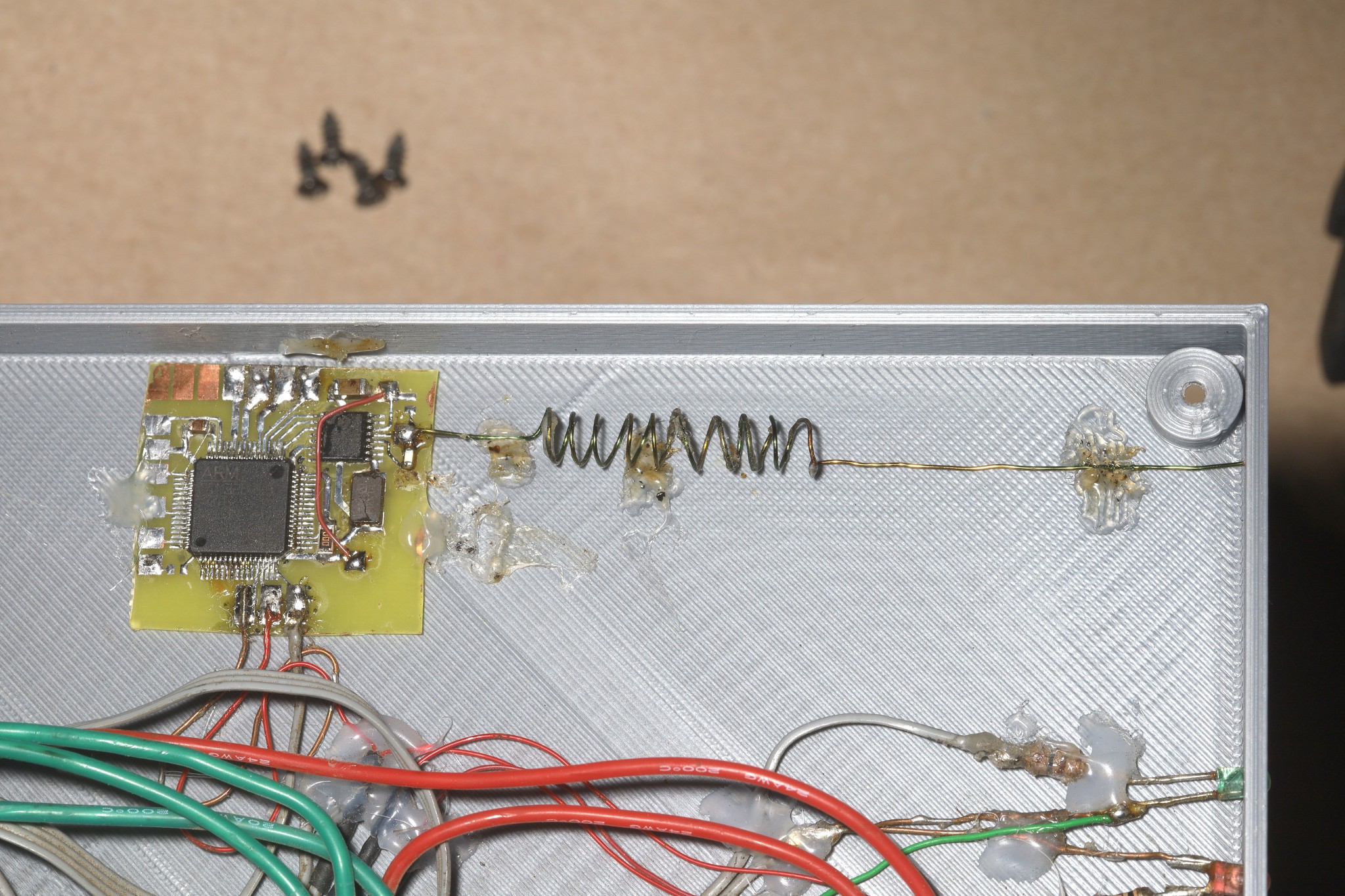
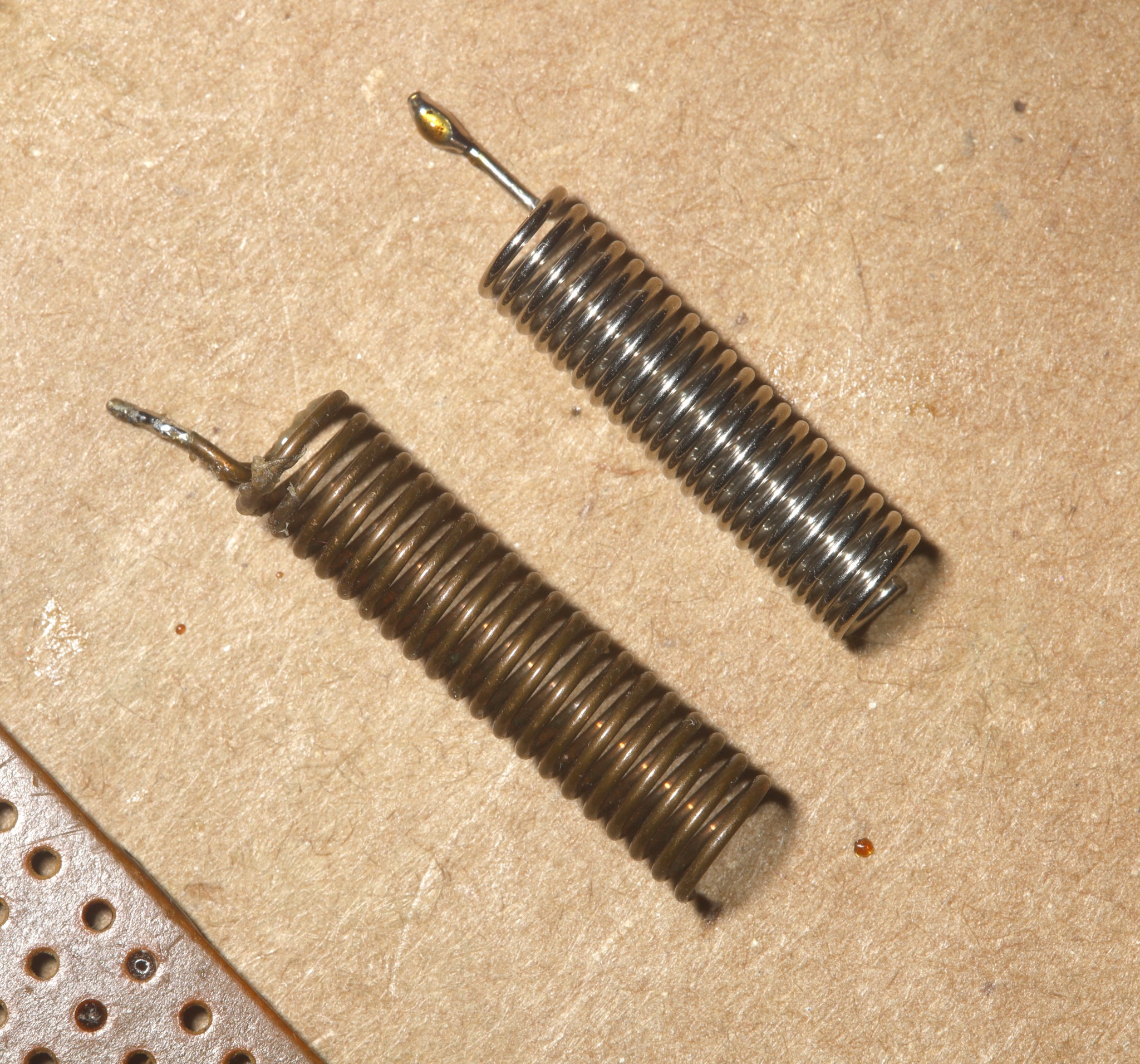
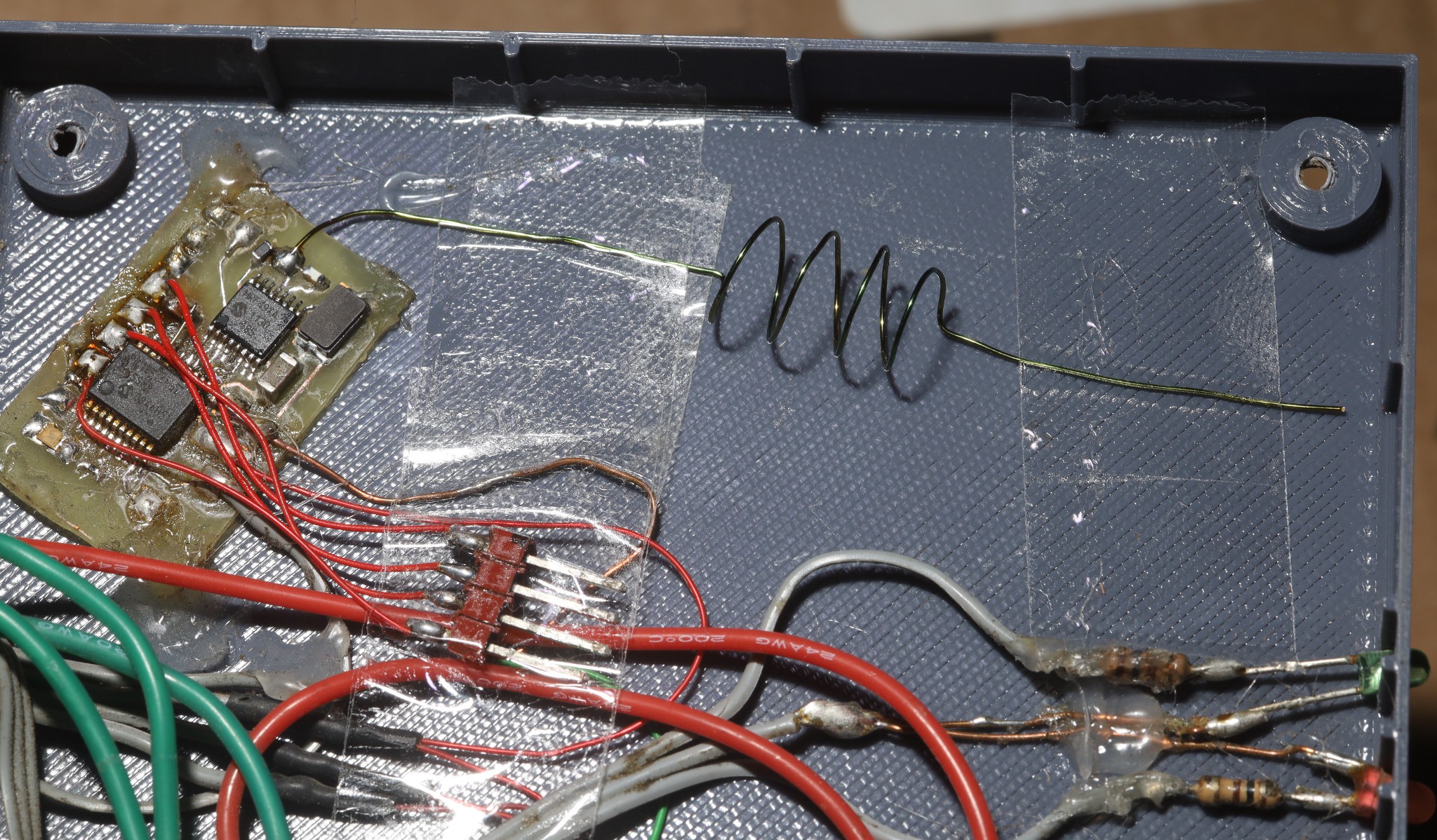
It was found that the antenna could be optimized by measuring the transmitter current. The receiver & antennas could be adjusted by plugging them into the transmitter. The density of a coil changes the electrical length independent of the length of the wire. This led to some antenna changes which made the biggest improvement in range but also increased battery usage.
![]()
![]()
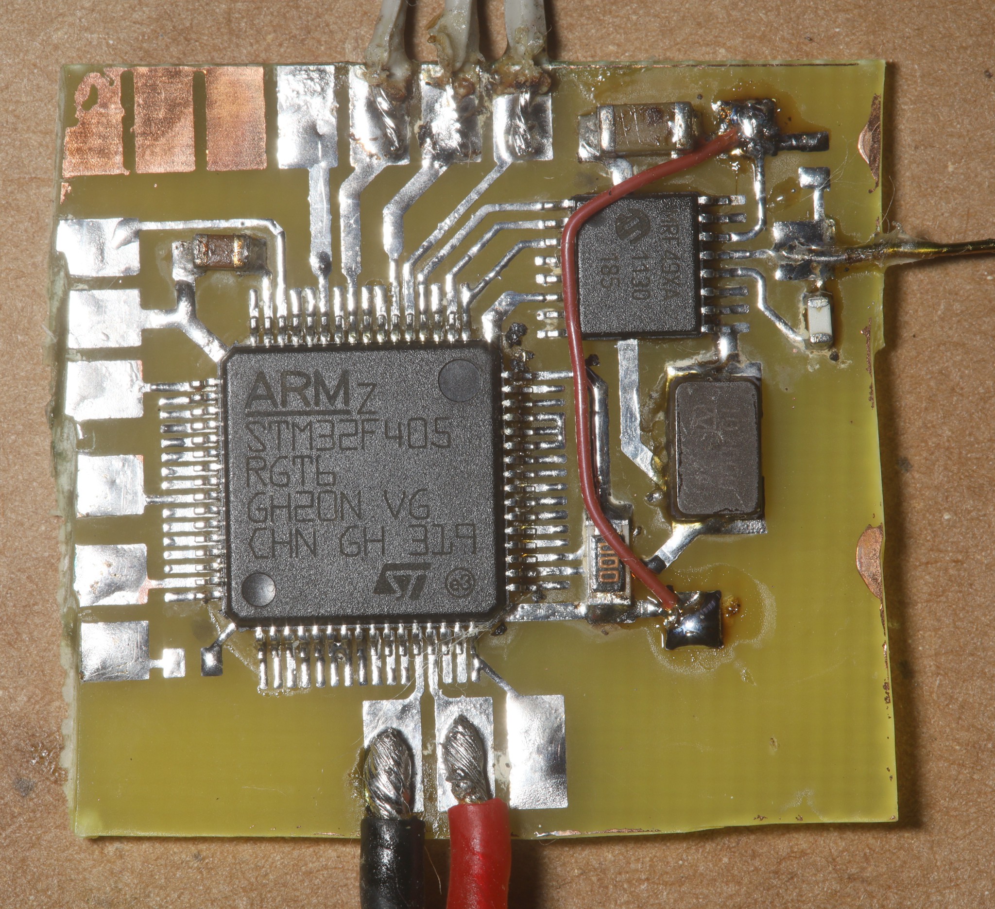
There was an effort to improve the reception by oversampling the PWM signal in a really fast microcontroller. It didn't make any obvious improvement that would justify the cost, because the hardware already does schmidt triggering.
-
Caster adjustment
07/20/2024 at 18:04 • 0 commentsDecided to increase the caster from 10' to 20' in order to stabilize cameras more.
![]()
This made it more reluctant to steer & increased the turn radius. Unfortunately, the center line is not straight ahead, so it tries to turn off center.
![]()
![]()
![]()
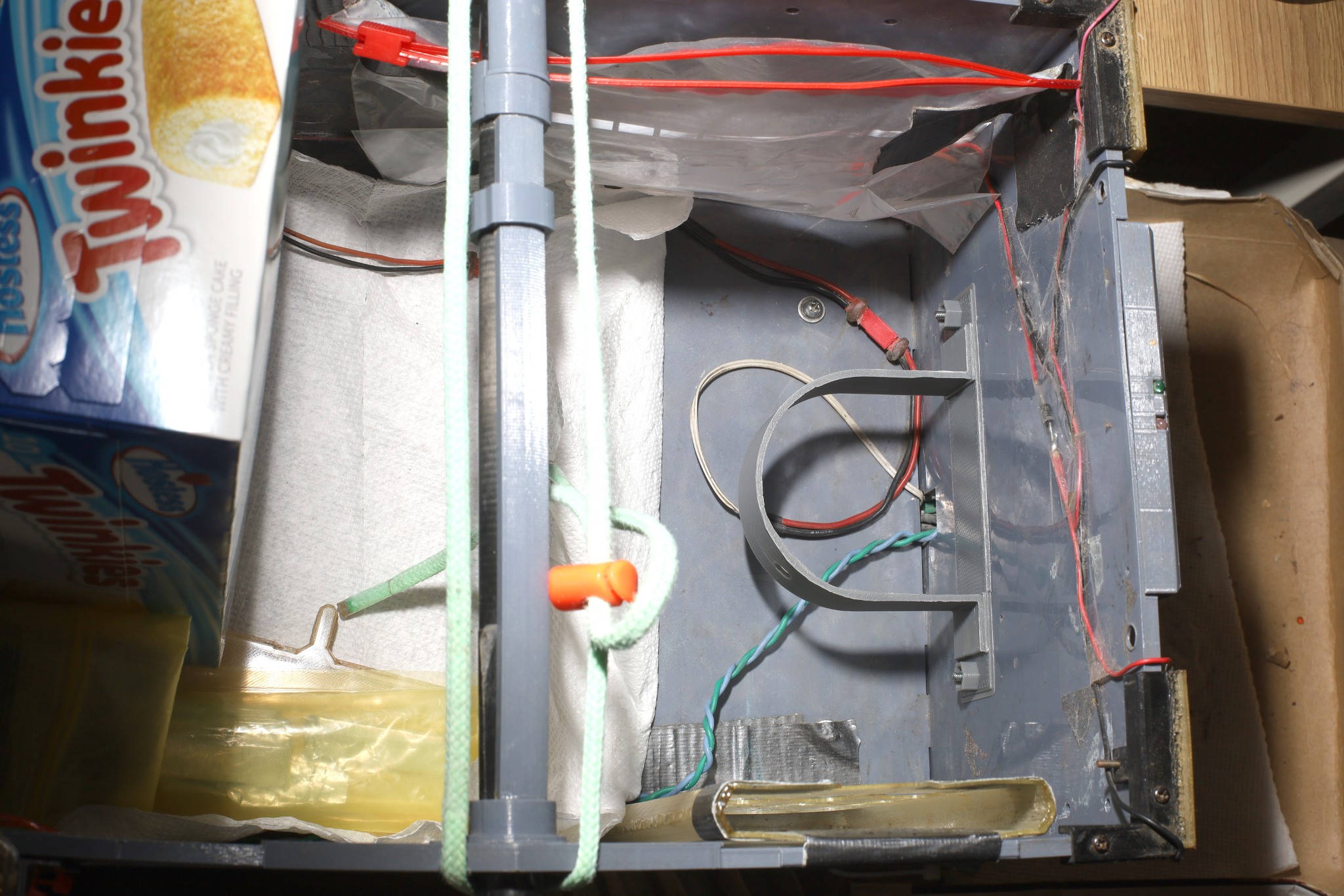
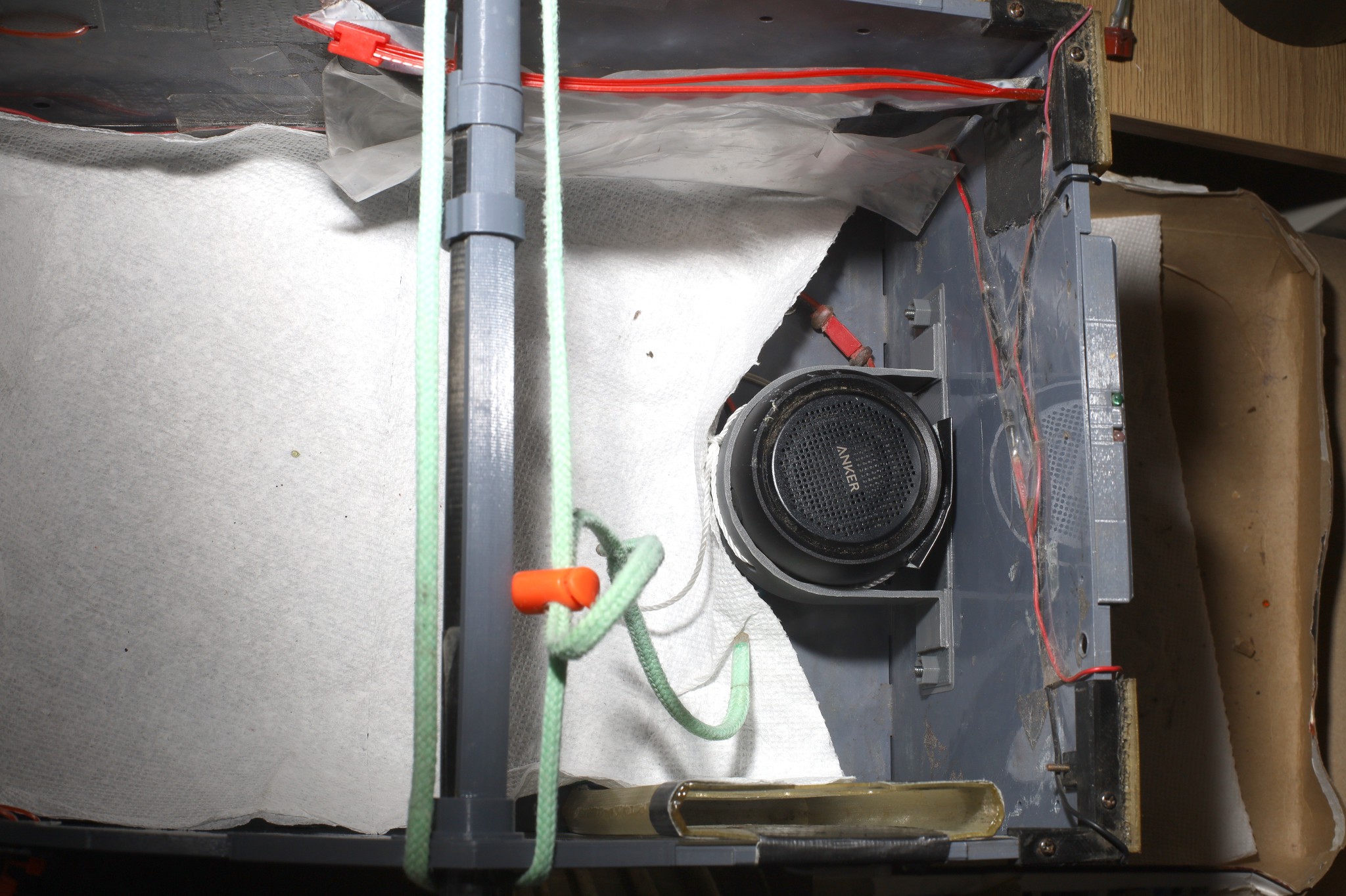
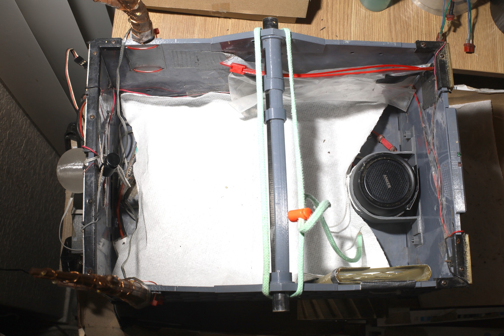
An aft speaker mount was created, to make it easier to hear in leash mode. This costs a lot of payload space, so it's only used for audio books.
![]()
![]()
![]()
![]()
![]()
Another PLA ball link wore down until it fell off. In replacing them, noted the support side should face away from the ball link to make it fit tighter. Then it should be heated to make the PLA conform. If the motion is too stiff, the leash is going to oscillate instead of converge on a heading.
-
Braking algorithm
05/22/2024 at 23:36 • 0 commentsLions do 2 hill climbs every week. Leash mode on hills has been a problem that desperately requires a brake algorithm. The leading braking algorithm is to always copy the motor angle when the leash is above minimum to a reference angle. When the leash is below minimum, apply greater reverse torque as the motor angle offset goes farther above 0. Apply greater forward torque as the motor angle offset goes farther below 0. For angle offsets above 90 deg, reset the reference angle to keep the offset always at 90. Maximum angle needs to be adjusted so it can't wrap around. Hopefully it wouldn't run away.
A failure of the motor encoder could make it run away. It's the 1st case of power being applied by an encoder instead of a user input. It seems less likely than a leash failure.
This wouldn't apply in stick controller mode. Stick controller mode still usually wants to coast.
![]()
![]()
This creates a springy stop, but it damps. It hasn't escalated to the point of needing D & I. It's only using 1 PID controller for both motors so it only supports P. Tests showed it stopping on common road inclines without a payload. Steeper inclines & with a payload are still going to be disasters. It has an easier time climbing than descending. Stopping the forward inertia of a descent is the tricky bit.
Power is limited to 50% because of the tendency of the motors to overheat when stalled. Steering stays in the last position before the leash was retracted. This was a hard won algorithm. It can't determine the leash direction when retracted. Centering when the leash was retracted would make slow turns impossible so it neglects the steering in brake mode. If the braking doesn't hold, it swerves to 1 side. The initial deceleration during a steep descent is usually a disaster. Turning the leash off when it's parked on an incline causes it to start rolling.
It's an improvement from yesterday when steep descents required outrunning it & it was impossible to access food when climbing.
Braking in RC mode has been an extremely rare need. It's normally going fast enough in RC mode to not need braking while leash mode requires slow speeds. This would only engage in auto throttle mode. Past attempts only resulted in oscillation. It would need another PID controller.
----------------------------------------------------------------------------------------------
A few days of practical driving showed many more ways braking improved the experience beyond the usual killer cases. The biggest change is it automatically stops at very intersection instead of rolling uncontrollably towards destruction. It has enough power to stop with a payload on a typical ramp. Lions were previously stopping short of intersections, instinctively expecting the roll.
-
Waterproofing ideas, 433 migration
02/04/2024 at 08:38 • 0 comments3 years on, it's become quite clear that the paw controller doesn't have to be ambidextrous. It's a minor convenience in the scheme of things. It manely has to be right pawed because lions eat with their left paw. The convenience is enough to keep an ambidextrous variant around but a waterproof controller could come back into the picture if it was right paw only. The current sock provides a lot more protection from rain than before, but a fully enclosed controller is needed for true running in rain.
The steering could go back to 4 tact buttons. Throttle could go to 2 buttons. They could all be boundary switches to avoid the wear of tact buttons. The motors & sensors are another problem. The motor sensors would have to go in a potted enclosure. Waterproofing gets expensive.
----------------------------------------------------------------------------------------------------
Control over the years was done over 433Mhz 16mW CC1101, 2.4Ghz 60mW xbee, 915Mhz 100mW xbee, custom 915Mhz 100mW. The 2.4Ghz was 1st to become unusable. Then a drive through Manhattan showed 915Mhz was now completely unusable in that environment. The decision was made to go back to 433Mhz with a custom 100mW transmitter based on the Si4463 for transmission & the ancient MRF49XA for reception.
![]()
![]()
The mane challenge with this was getting decent range with antennas that fit in the limited space. Got 1/4 wave antennas to fit with coils but it only went 20ft. No radio ever got beyond 50ft because the truck is near the ground. The leading culprit is the matching circuit. Lions use very simple matching circuits. The receiver just has a 47nH inductor between + & -. The transmitter just has a 390nH inductor to Vdd. The full matching circuits don't seem to offer any benefit besides suppressing harmonics.
The Si4463 shows a receive sensitivity of -129dbm. The CC1101 shows -116dbm. The MRF49XA shows -110dbm. It might be time to replace the receiver, but the Si4463 requires a lot more pins & is expensive. The Si4463 can also change channels a lot faster than the older chips but...
There haven't been any obvious benefits from frequency hopping. It seems to hog more of the spectrum, if anything. The kinds of conflicts encountered in the field are always usage of the entire spectrum rather than a single channel. Lions have dreams of freeing up bandwidth by using minute long frequency hopping patterns over a very wide range but that would be a difficult problem. Only 433-435 is legal. Some frequencies would need frequent usage for synchronization packets. The only benefit would be less detectable spectrum usage.
Frequency hopping requires encoding the current channel in the packet to avoid crosstalk. Finding enough bits usually entails encoding different fields using modulus operators instead of bitmasks. A bitmask can encode 4 channel states & 17 speeds in 7 bits. A modulus can encode 7 channel states & 17 speeds in 7 bits.
Commercial 433 systems seem to be in the $150 range for 800mW. Nowhere near the required size, but they have full size antennas, proper matching circuits.
https://www.foxtechfpv.com/rlink-433...xrx-combo.html
There's a $25 chinese version if you have an aliexpress blessed credit card.
https://www.aliexpress.us/item/2251801693568177.html
The aftermarket RC parts business has otherwise all gone to DJI.
-
Translucent controller
07/03/2023 at 22:13 • 0 comments![]()
![]()
![]()
![]()
![]()
![]()
![]()
![]()
![]()
![]()
![]()
![]()
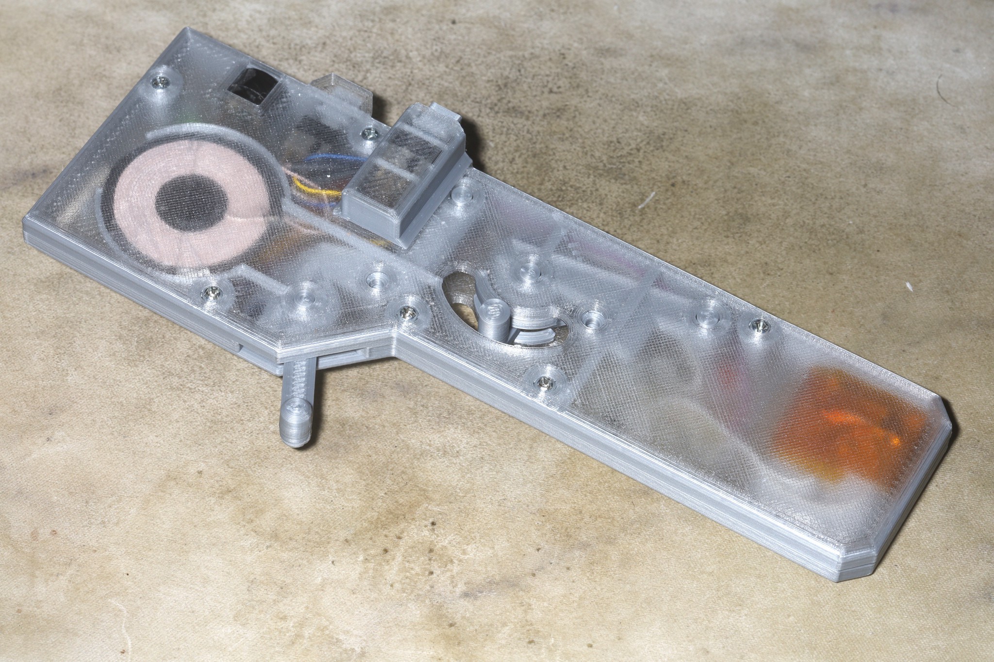
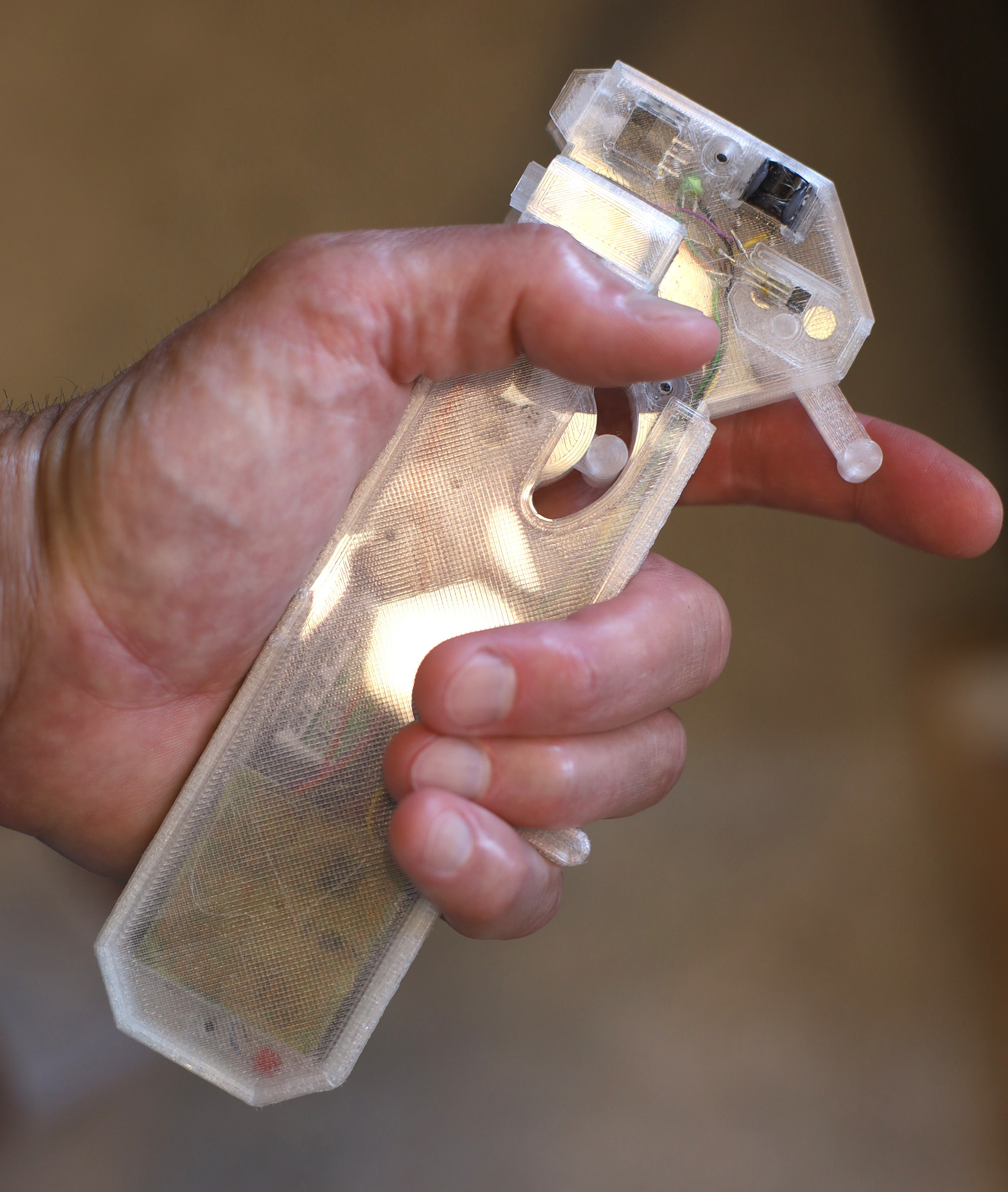
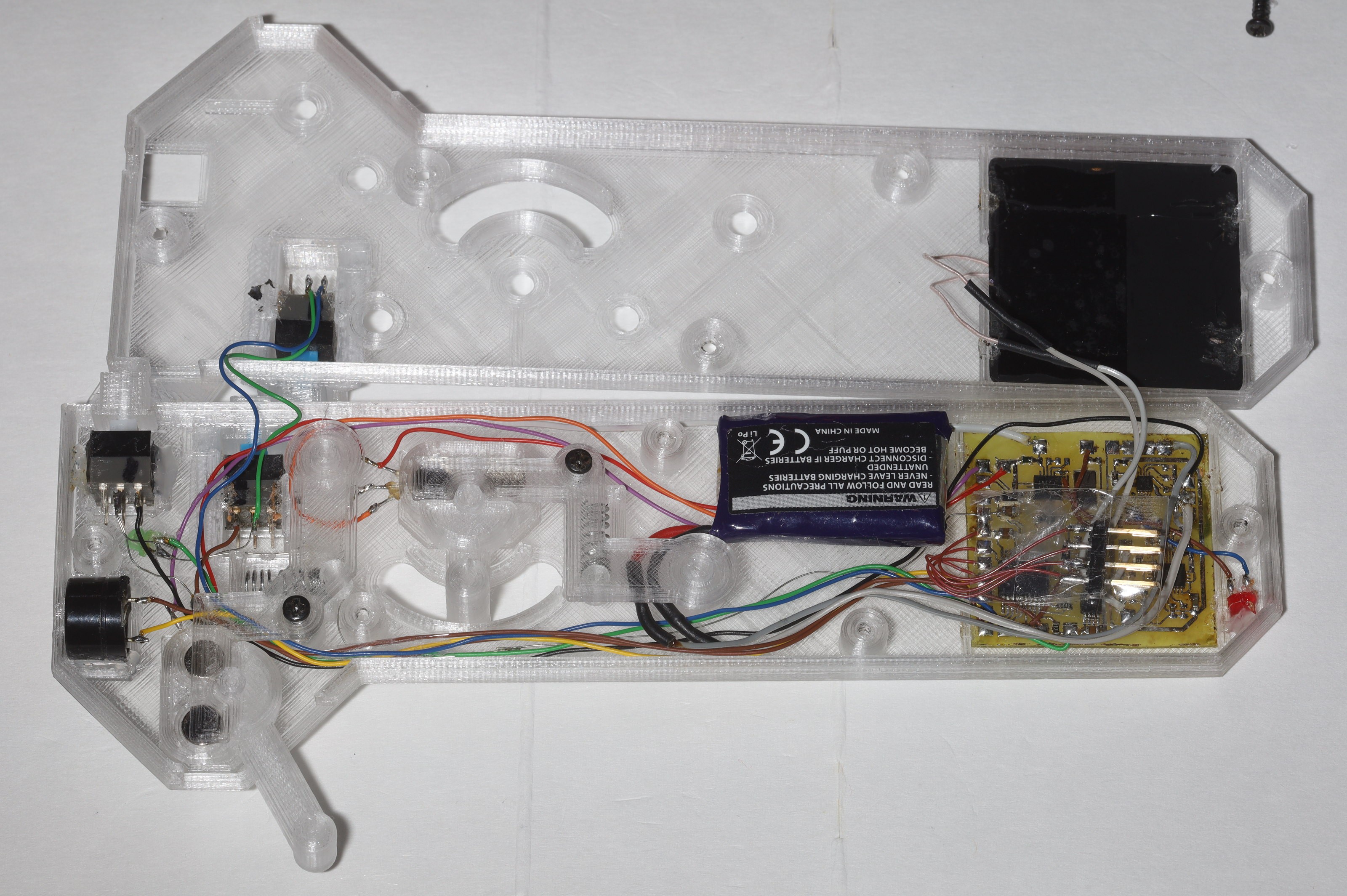
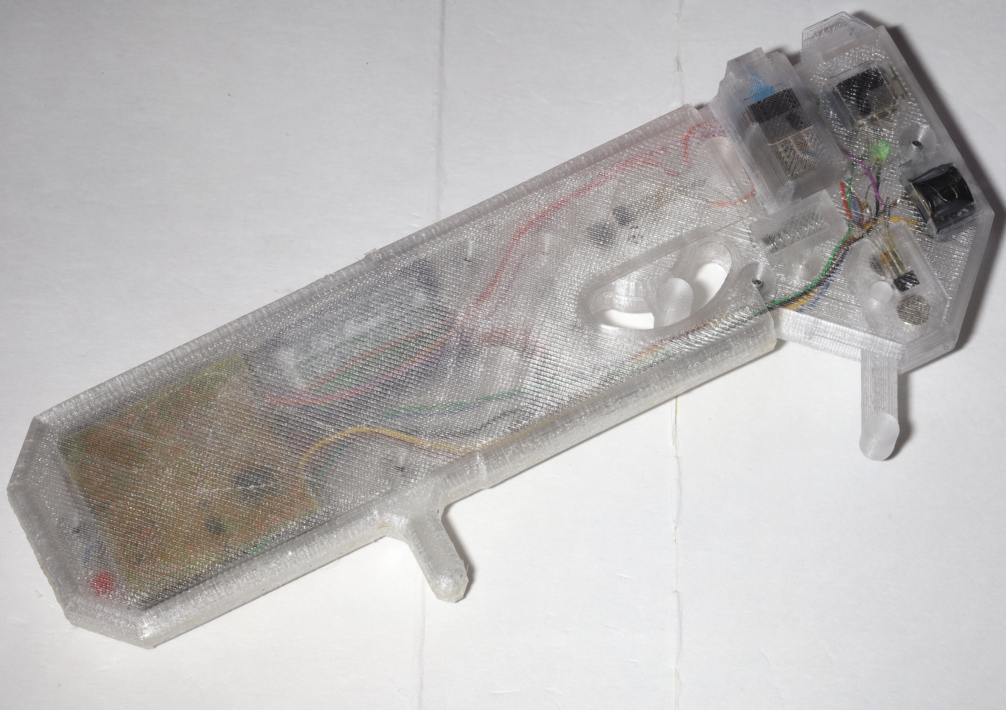
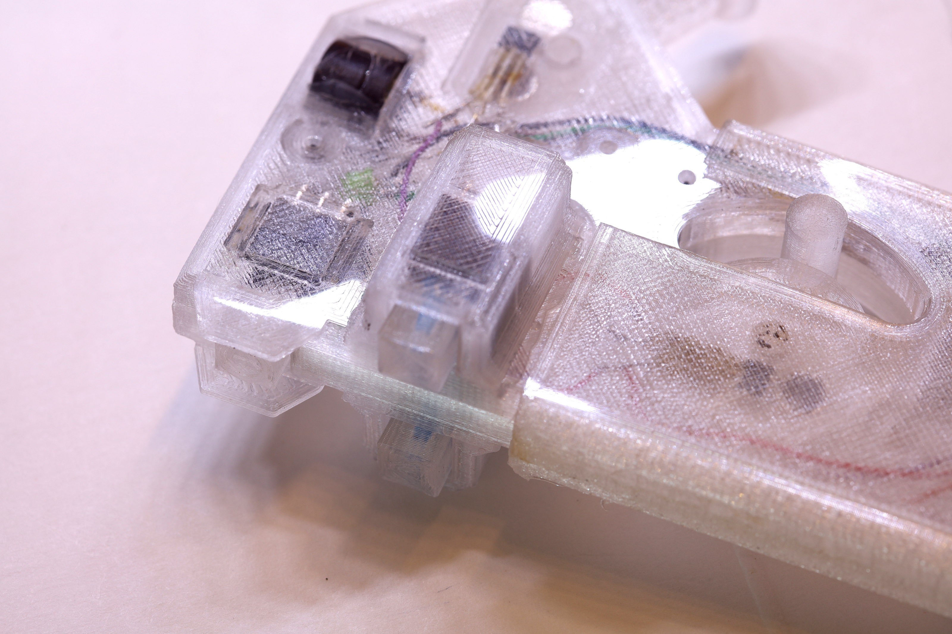
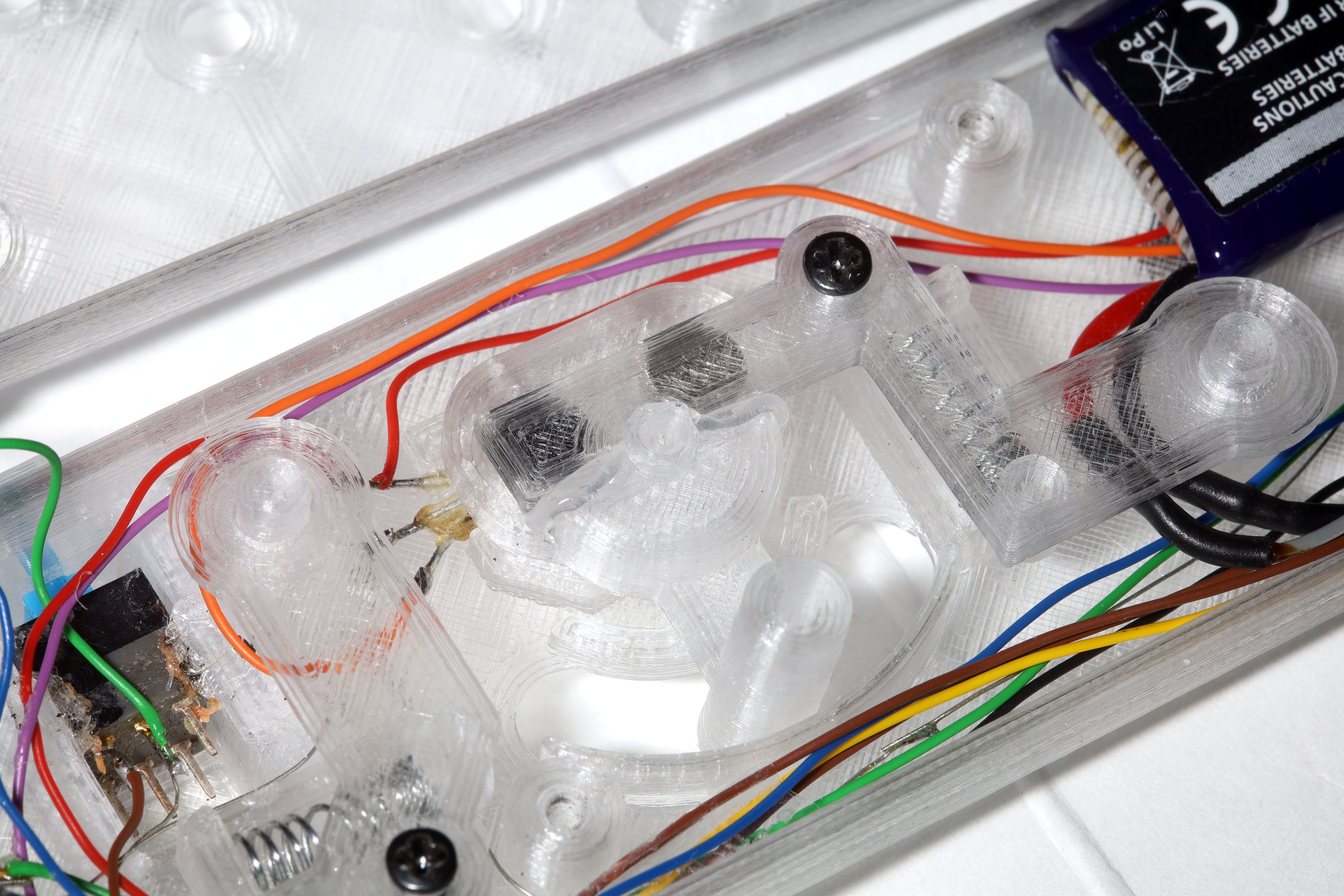
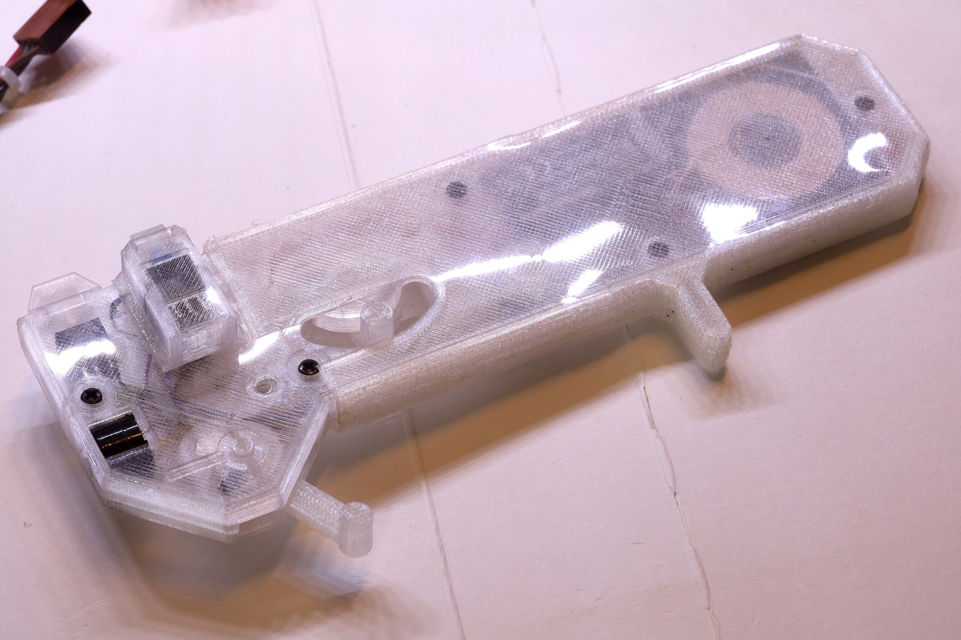
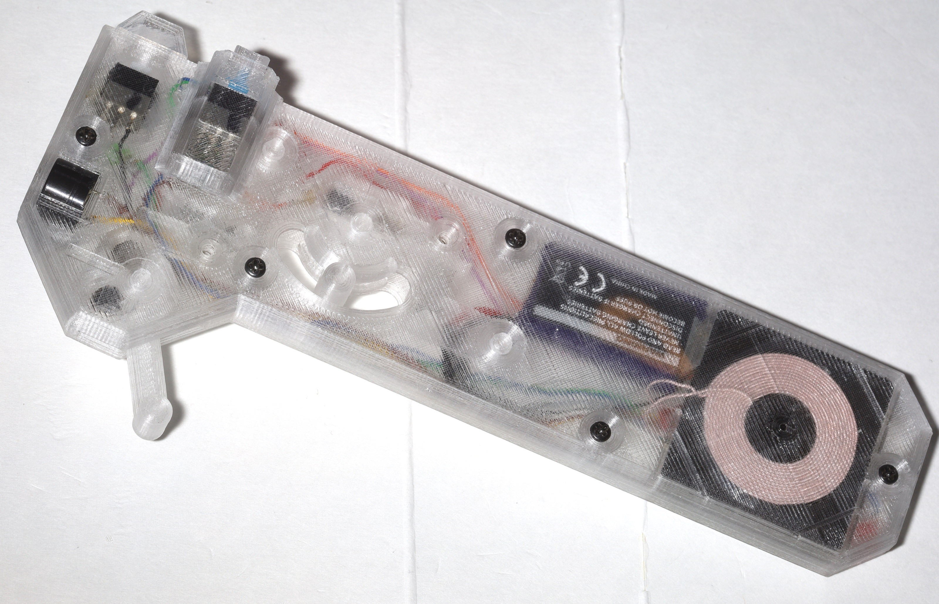
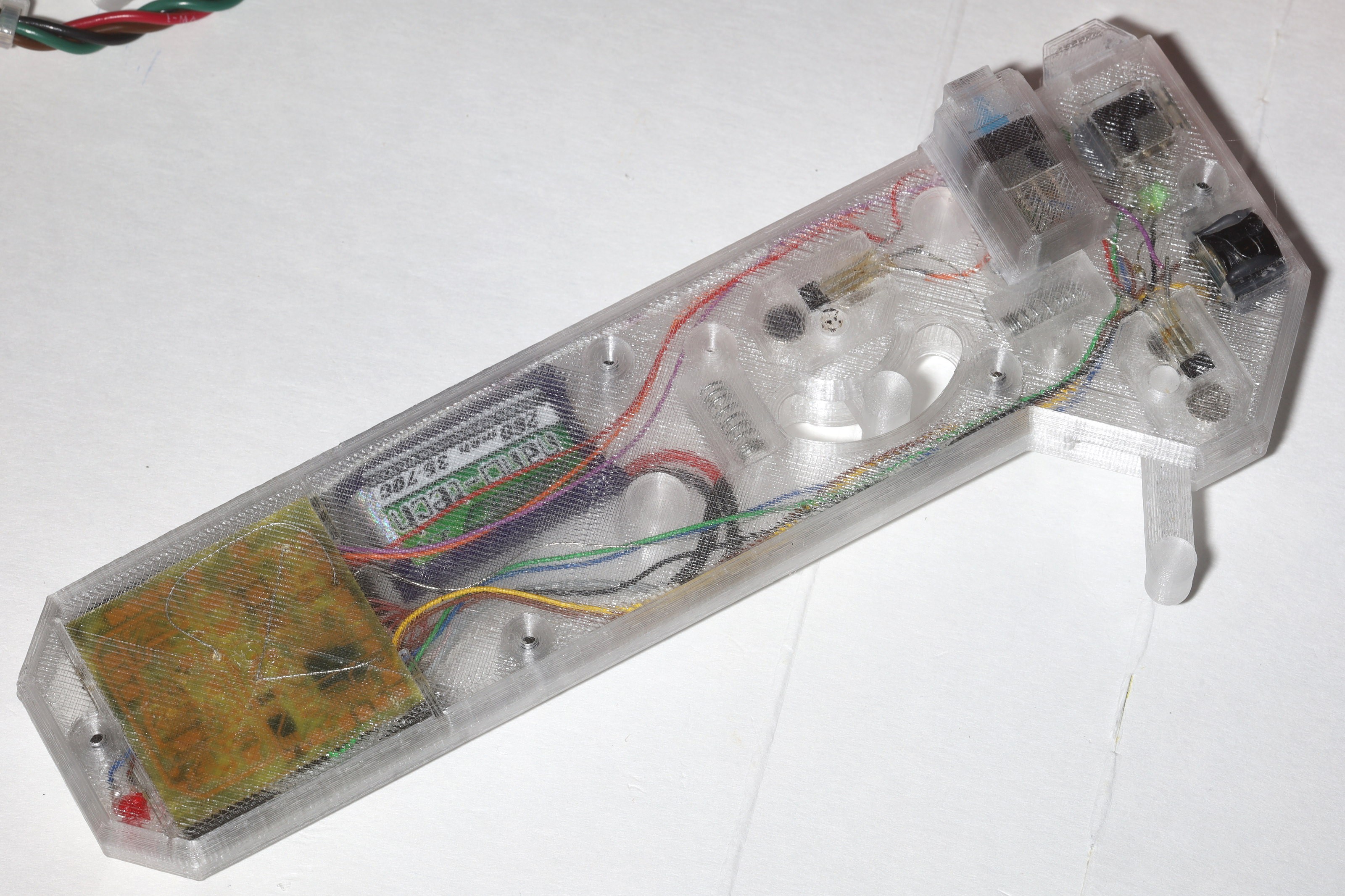
The current waterproofing & having all the LEDs on the inside worked, but growing pains with the orange beast finally reached a point where it was time. The mane problem was the power button constantly getting accidentally bumped when it was in leash mode. There were cosmetic desires for a glossy enclosure, better LED visibility.
There was once a theory that an easily accessed power button would allow emergency killing of the motors. In reality, there was never a case where accessing the power button would have killed a runaway vehicle. The throttle stick always worked. If it got stuck, it was faster to unstick it than reach for the power button. The power button would not interrupt the leash & the leash now does half the driving. It was finally time to add some minimal guarding to the power button.
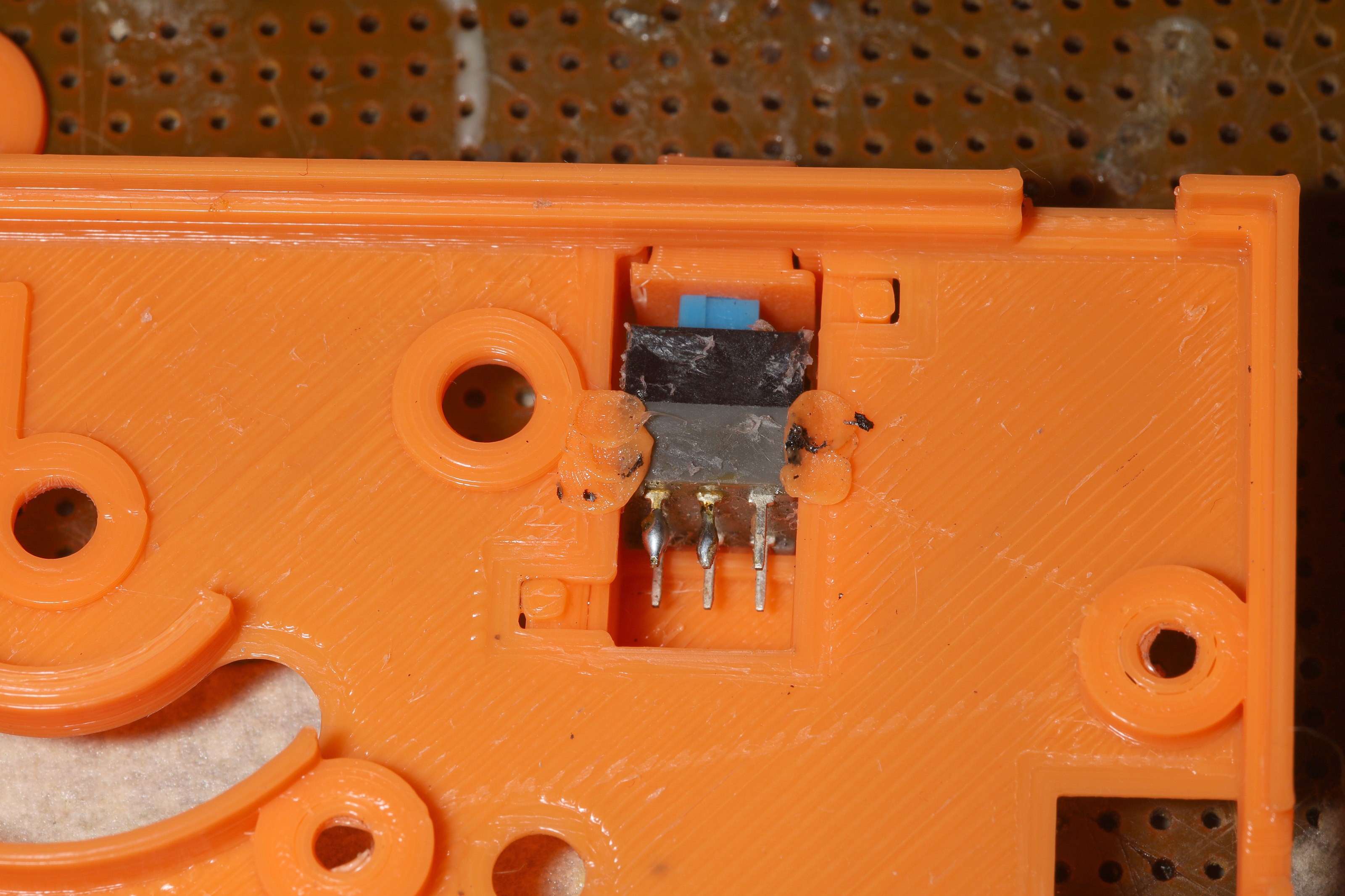
Assembly still takes 2 days, manely involving fiddly bits, removing the old circuit intact, reaming holes. PLA rivets are much harder to undo than hot snot. Undoing them melts plastic parts & removes a layer from the inductor. It pays to make the PLA rivets smaller.
The 1st sock rapidly turned yellow either from biological matter or sunlight. It definitely smelled like biological matter. There's a warping from the clamshell not fitting perfectly. Stick controllers still need lubrication. The hall effect sensors got moved to where the datasheet showed their hotspots + a .2mm margin & they reported nearly the exact center.
Time will tell if a glossy exterior was a good idea. The sock might grip better with a buildtak finish.
The next big feature is going to be OTA firmware updates. It's not possible to get the oral cues perfect as is. There should be a way to put the radio in a serial port passthrough by holding power & a direction button. Then it can run a bootloader. It's a big job.
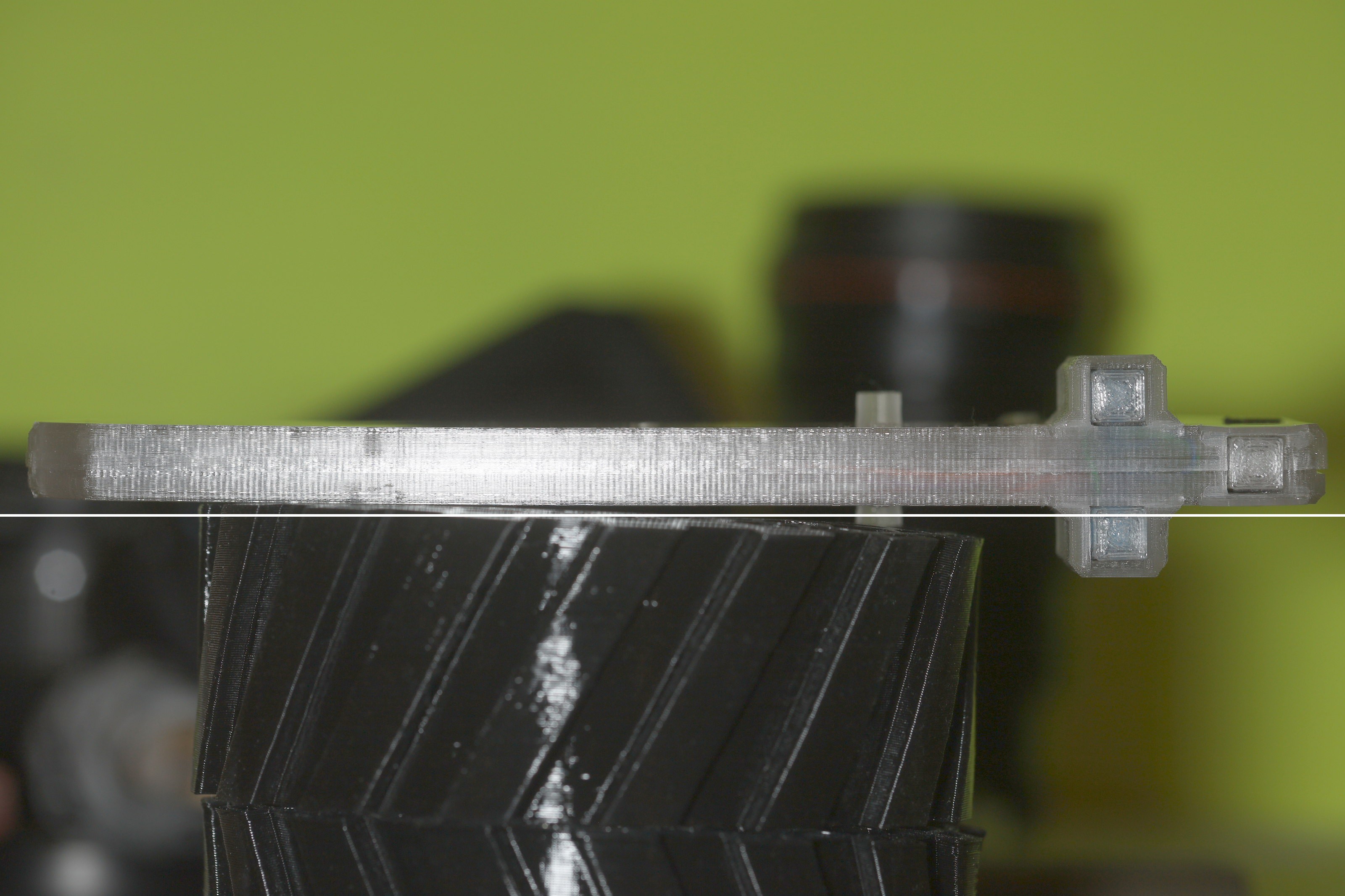
There's a growing desire to make the panels 1mm thick. They were made .8mm thick before lions were fully educated on PLA tolerances. There's a growing desire to make the power button exposed on 1 side & riveted in. The current hot snot system is a mess. Maybe it could be scotched over for waterproofing. Maybe it could be passively clamshelled in. The 3 button caps could actually be smaller. Still no better system than hot snotting the hall effect sensors.
The mane problem with the translucent controller is it gets hot in sunlight & alignments change.
-
Nose cone development
04/14/2023 at 23:39 • 0 commentsAs previously seen,
https://hackaday.io/project/176214/log/212713-propdrive-dreams
the cheapest way to get more speed was seen as creating a modular nose cone rather than expanding the motors, using hotter windings, or expanding the battery. The nose cone had to be field removable without tools, stowable so the leash could be accessed, & not cover the headlights.
![]()
![]()
![]()
![]()
![]()
The 1st step was converting the headlights to a narrow strip.
![]()
![]()
![]()
![]()
![]()
![]()
![]()
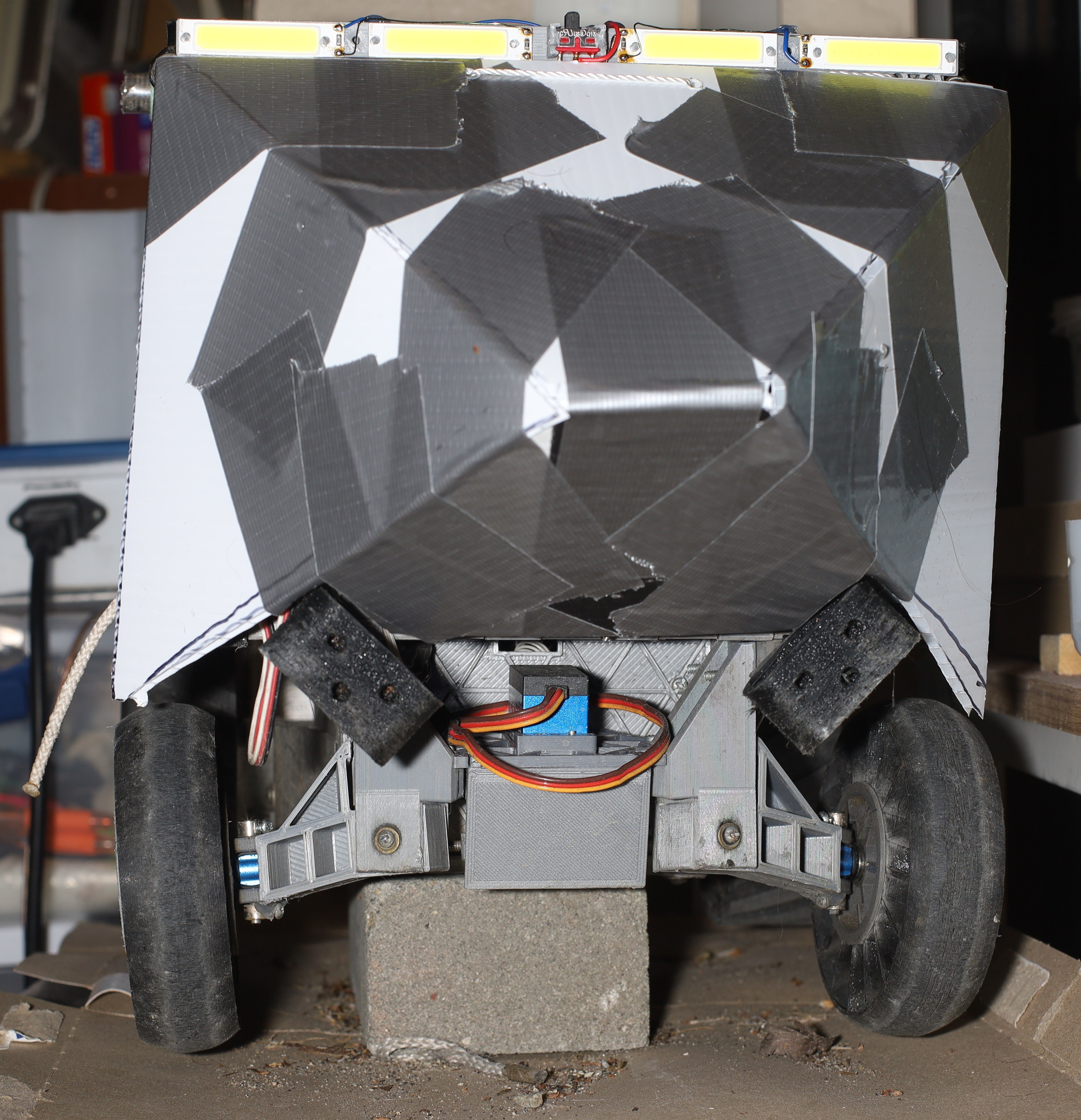
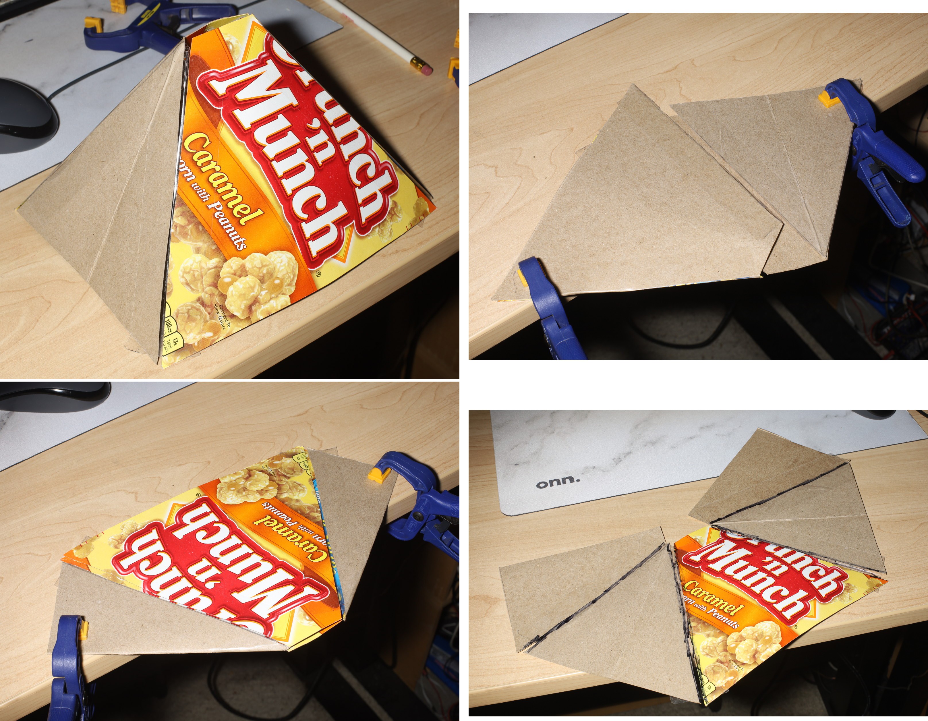
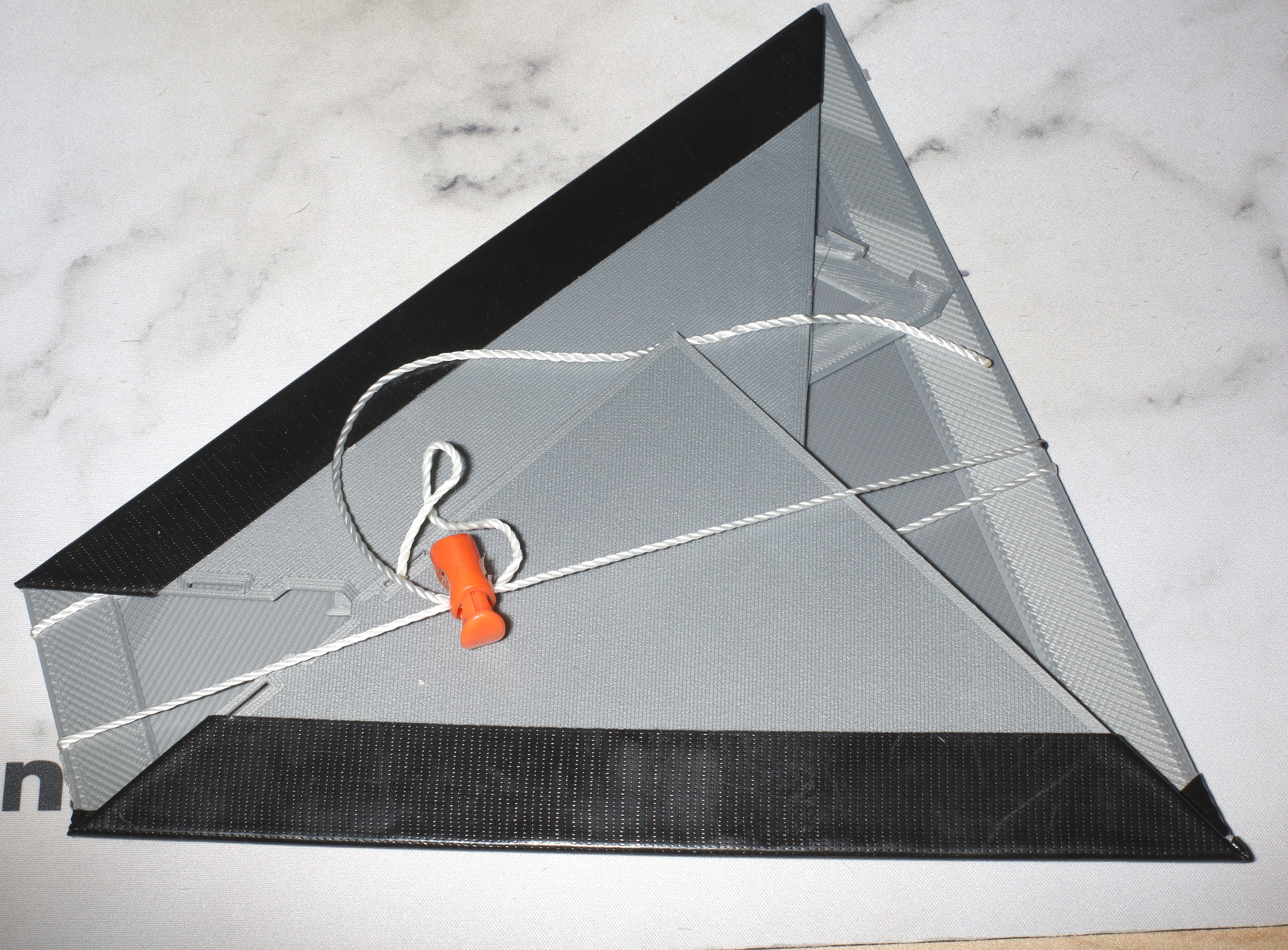
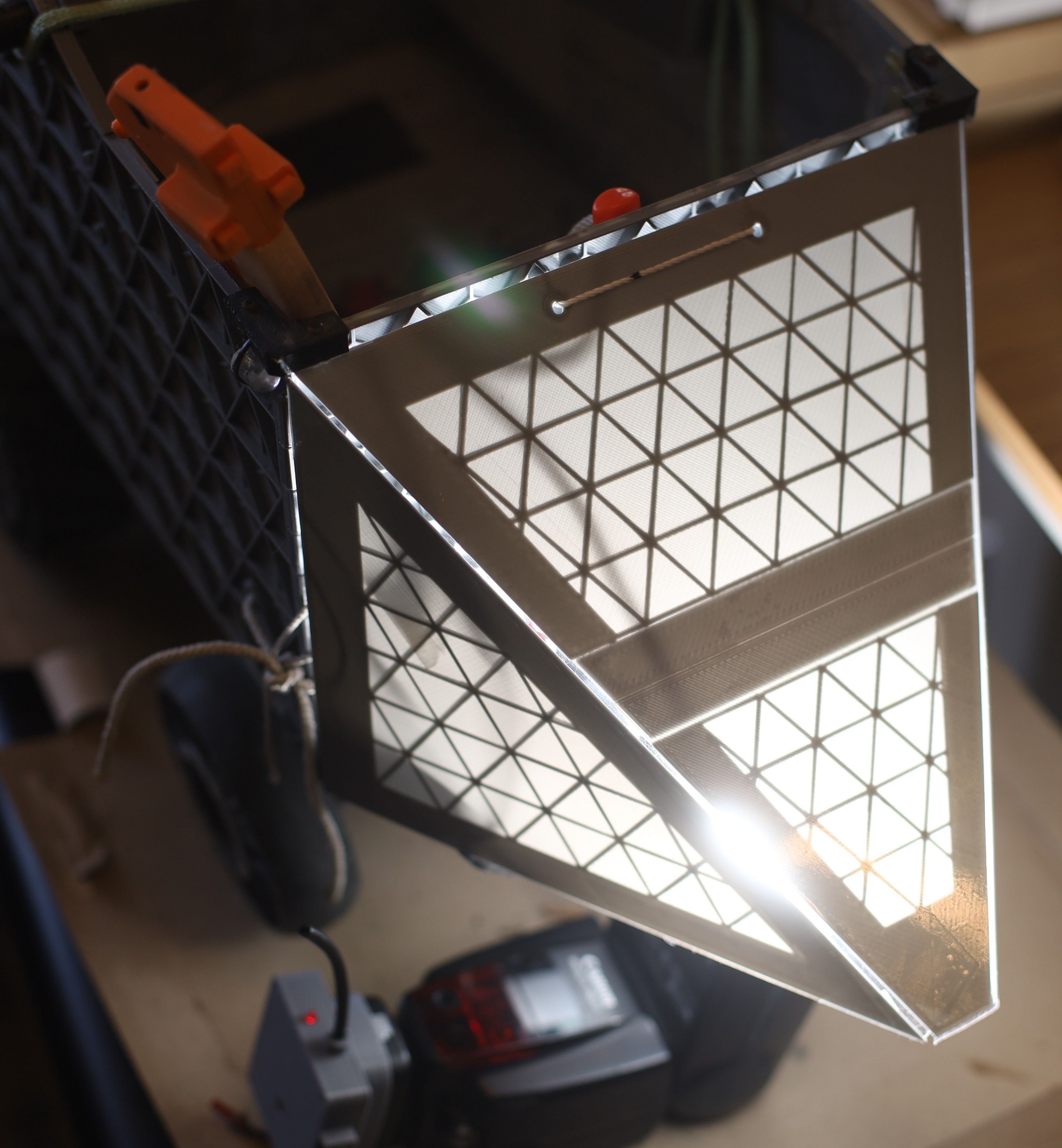
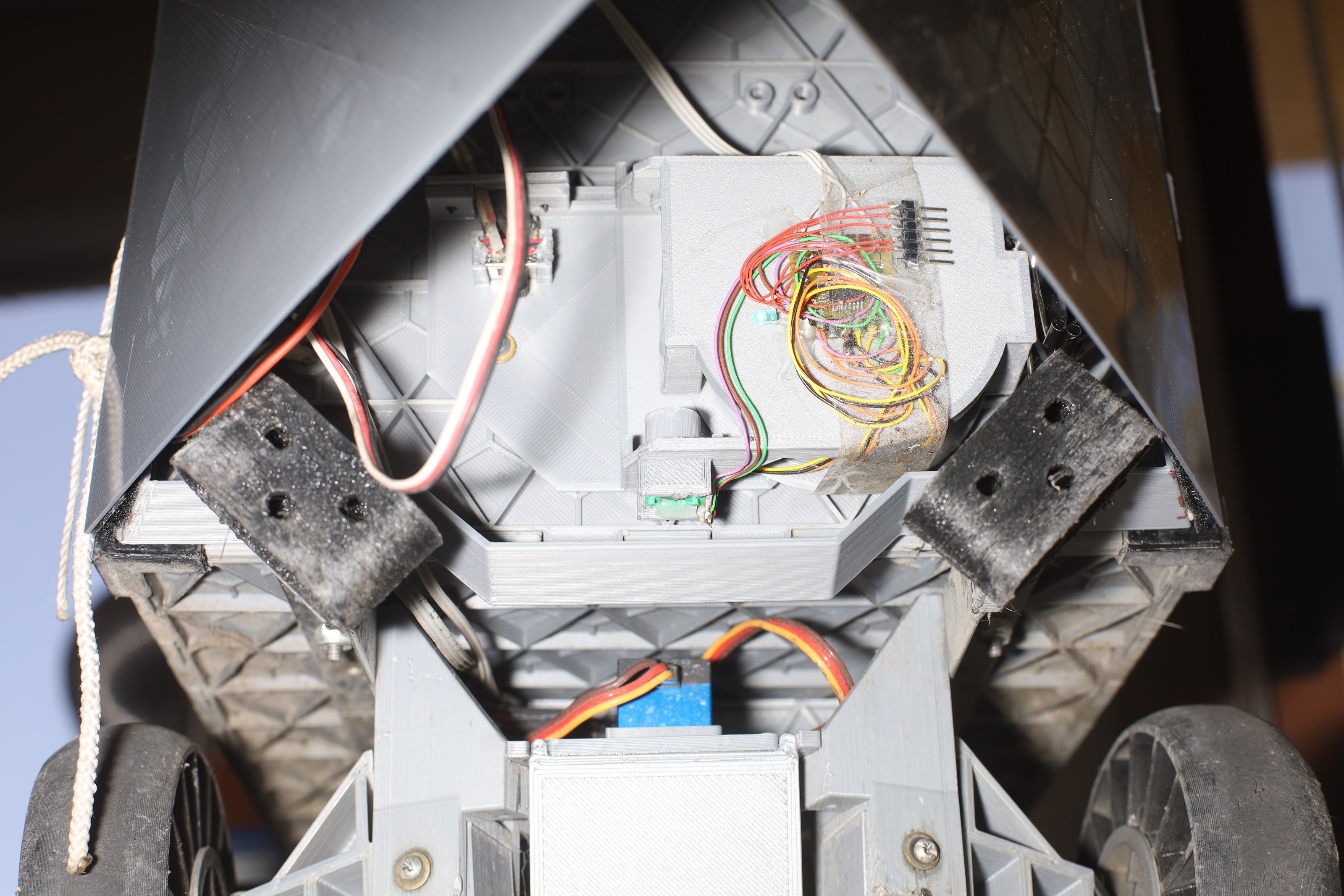
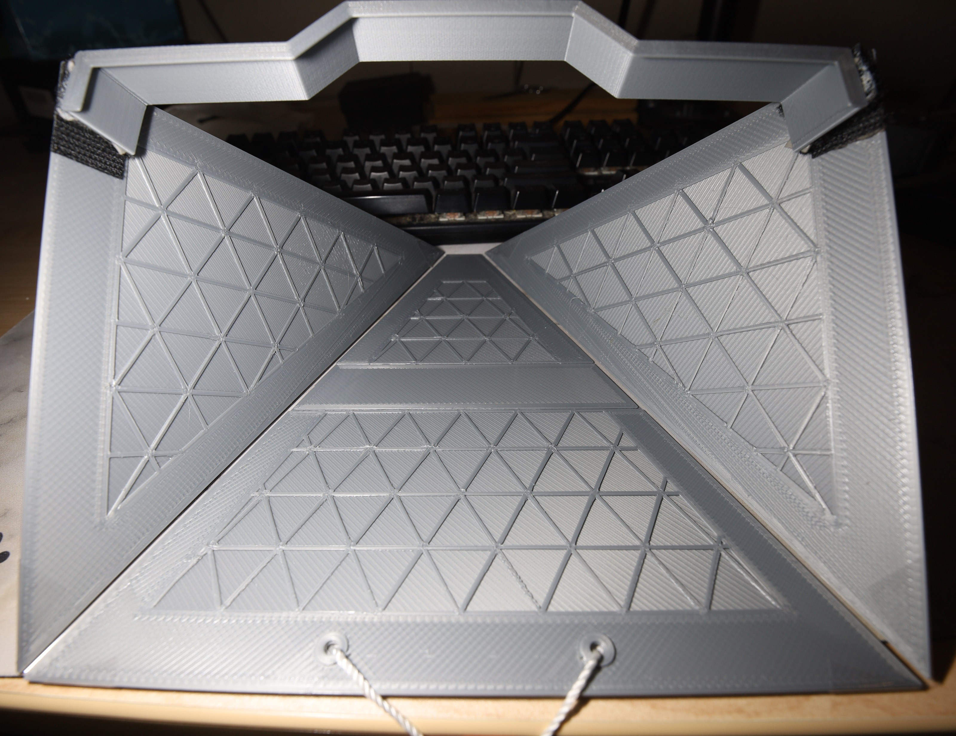
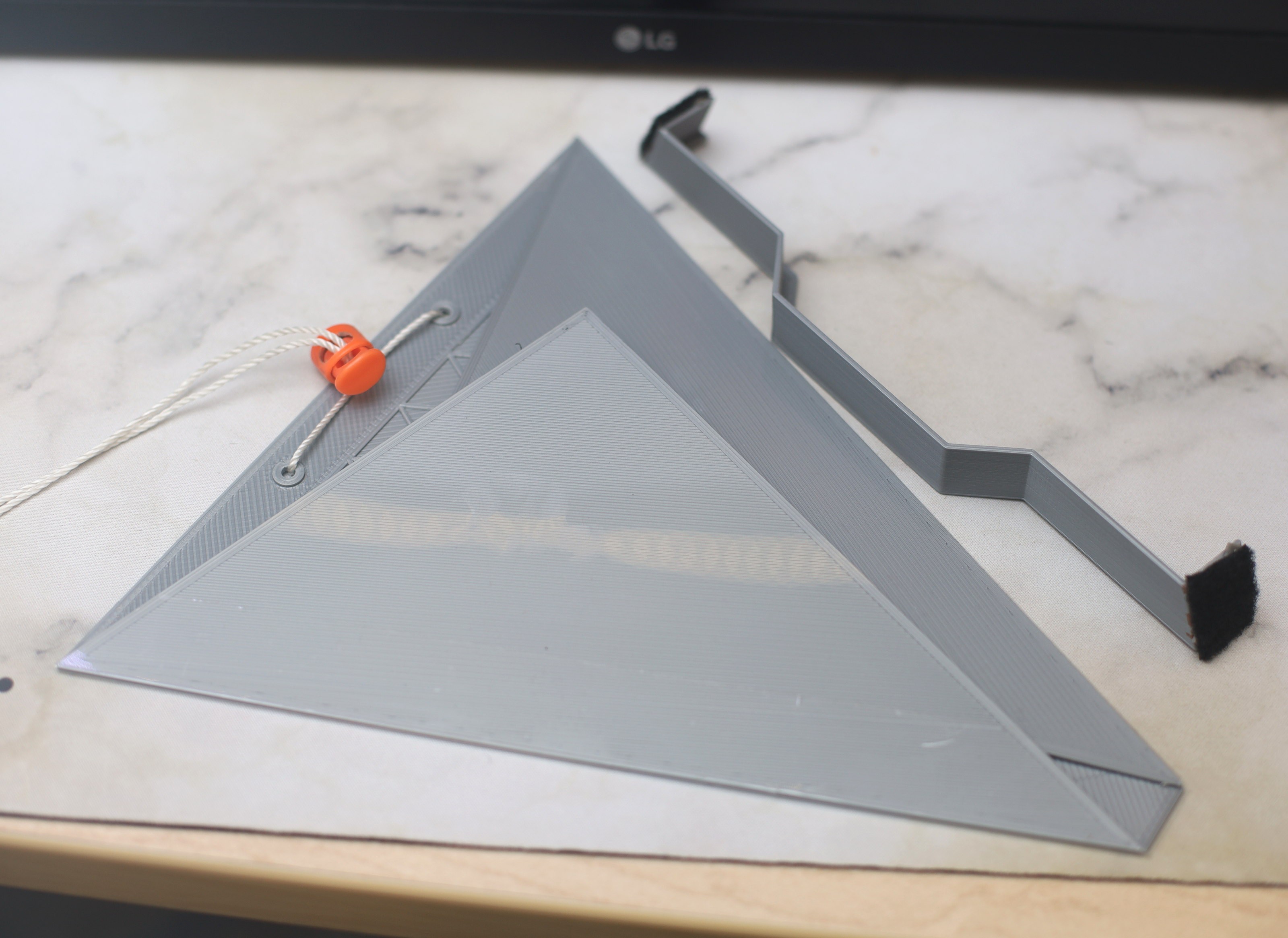
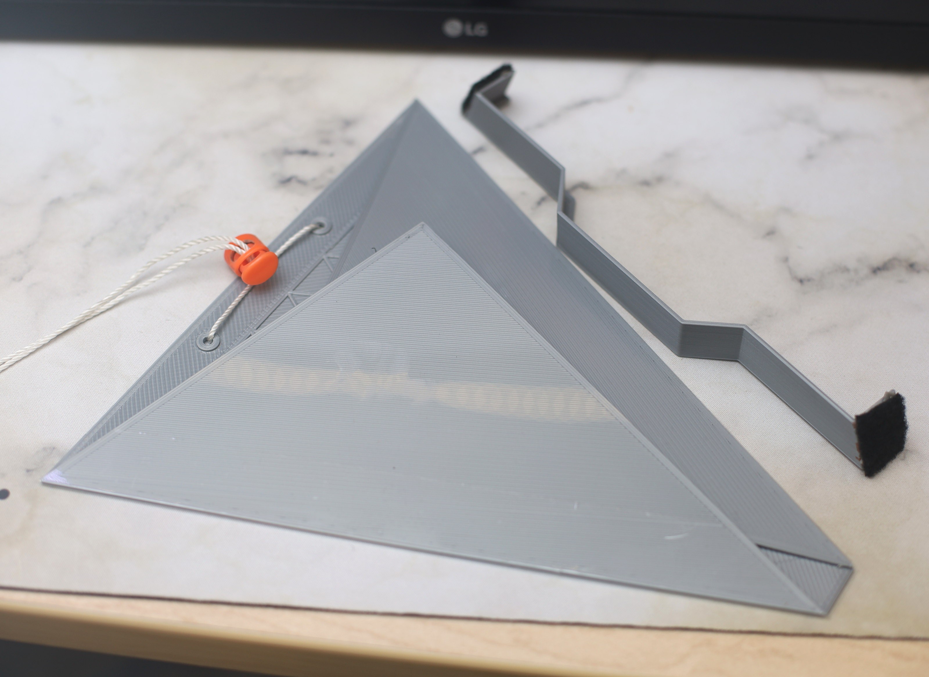
Various nose concepts followed, with cardboard, coroplastic, & PLA. After many miles, the best performing one was 3 sided with permanent string holding the bottom & a removable string farstening the top to the truck.
Ideal speeds with a nose cone:
#    dist    sec    min/mile
1    213    43    5:42
2    201    44    5:45
3    203    44    5:44
4    208    46    5:49
5    201    46    6:3
6    211    44    5:51
7    205    46    5:52
8    208    44    5:53
9    206    47    6:0
10    204    45    5:43
11    211    43    5:42
12    200    44    5:47
13    203    46    5:58
14    306    70    6:6
Typical speeds without a nose cone:
#    dist    sec    min/mile
1    208    48    6:9
2    305    73    6:24
3    405    98    6:28
4    408    103    6:43
5    404    100    6:35
6    404    100    6:34
8    400    101    6:45
9    407    110    7:14
Speeds with a nose cone were highly variable, depending on weather, payload, wheel alignment. Without a nose cone, it was guaranteed to have a hard time getting above 6:30/mile. With a nose cone, there was a possibility of it getting above 6:00/mile.
There's no correlation with the number of sides of the nose cone. A 2nd nose cone on the back might buy it more speed.
![]()
![]()
![]()
![]()
![]()
![]()
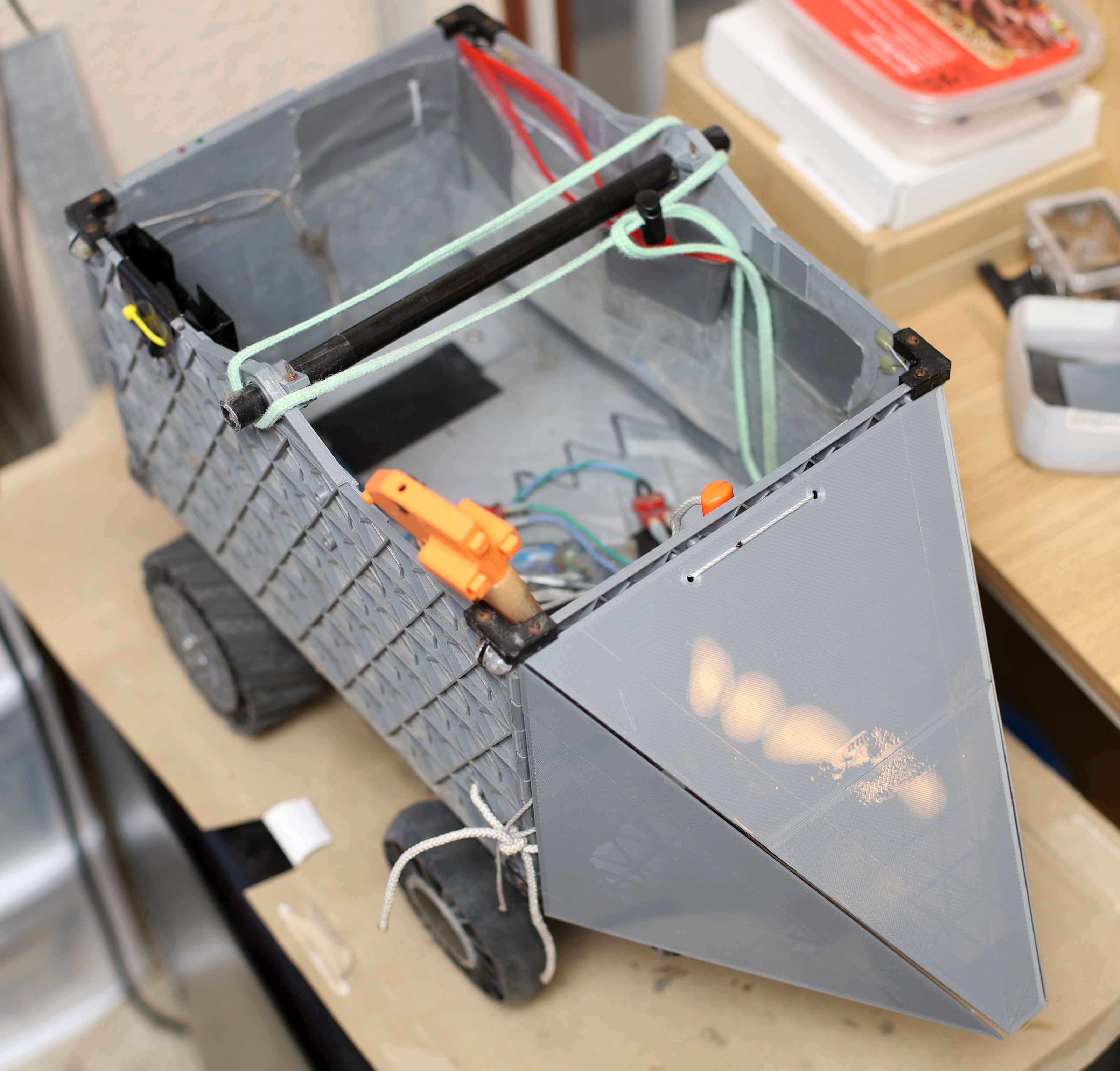
The latest nose cone is glossy & collapsible. It rests on the bumpers while clearing the leash.
-
Charging stand upgrades
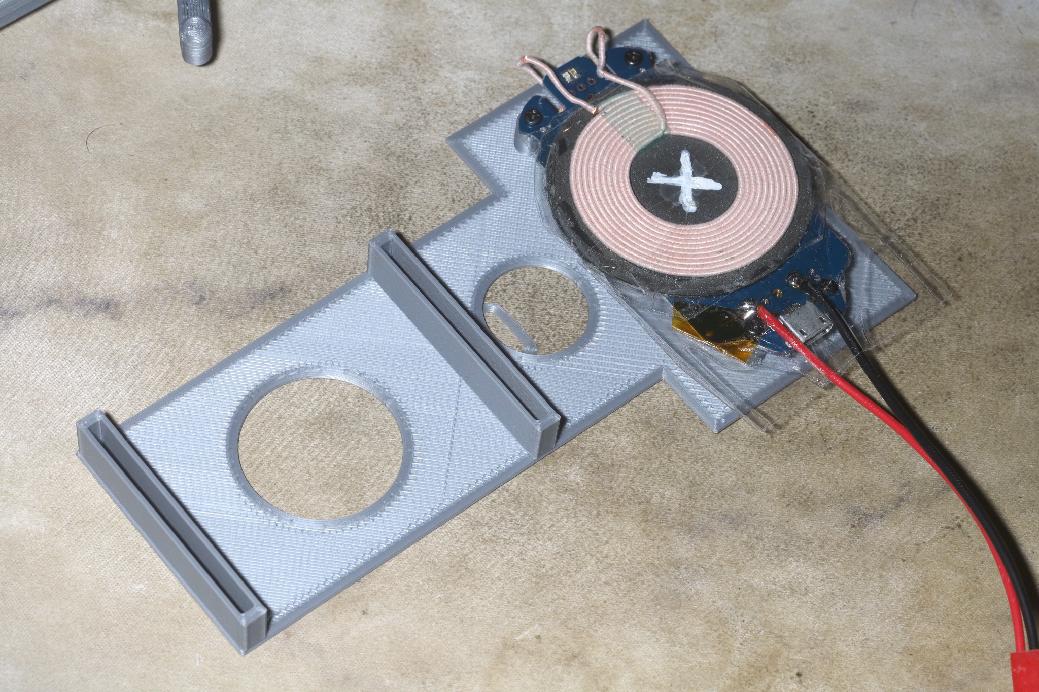
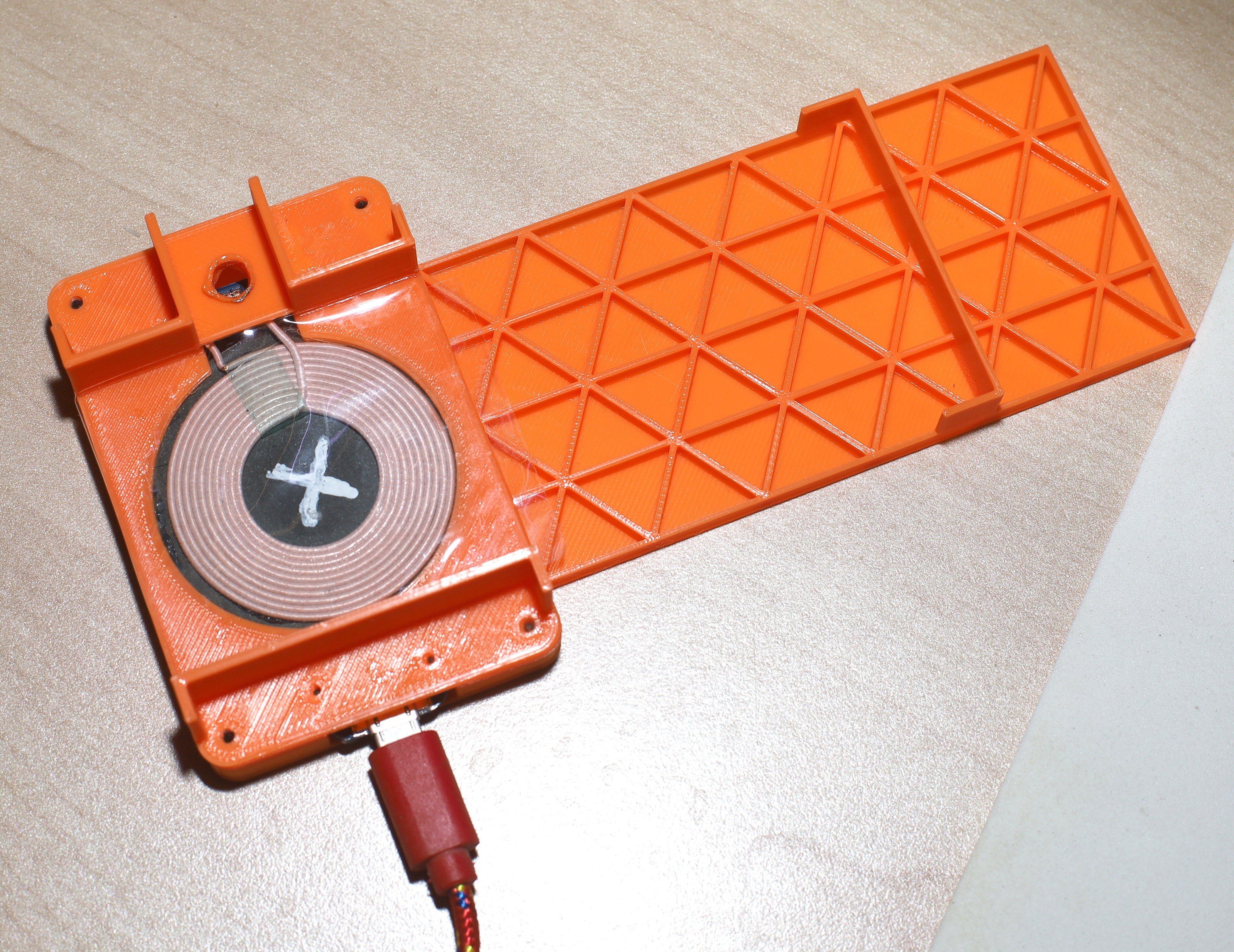
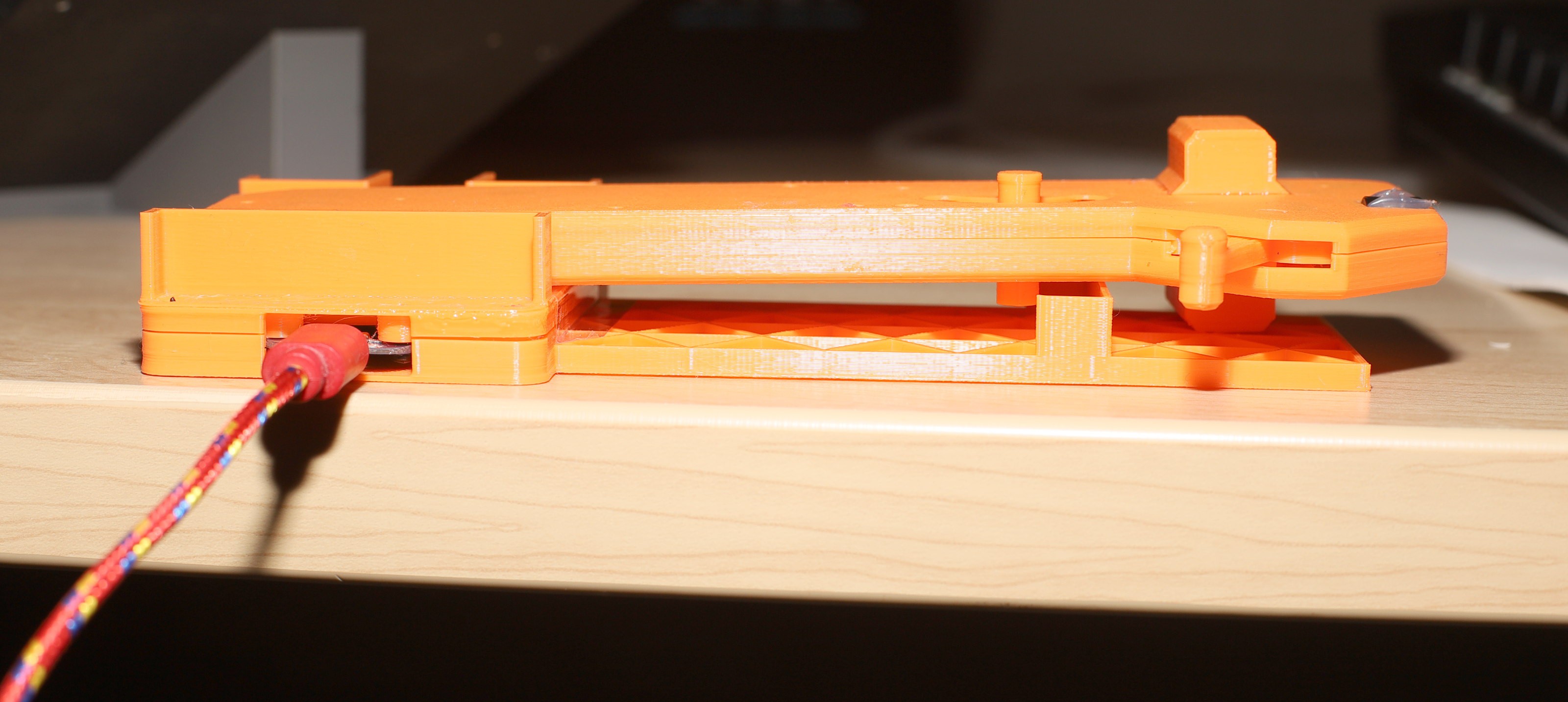
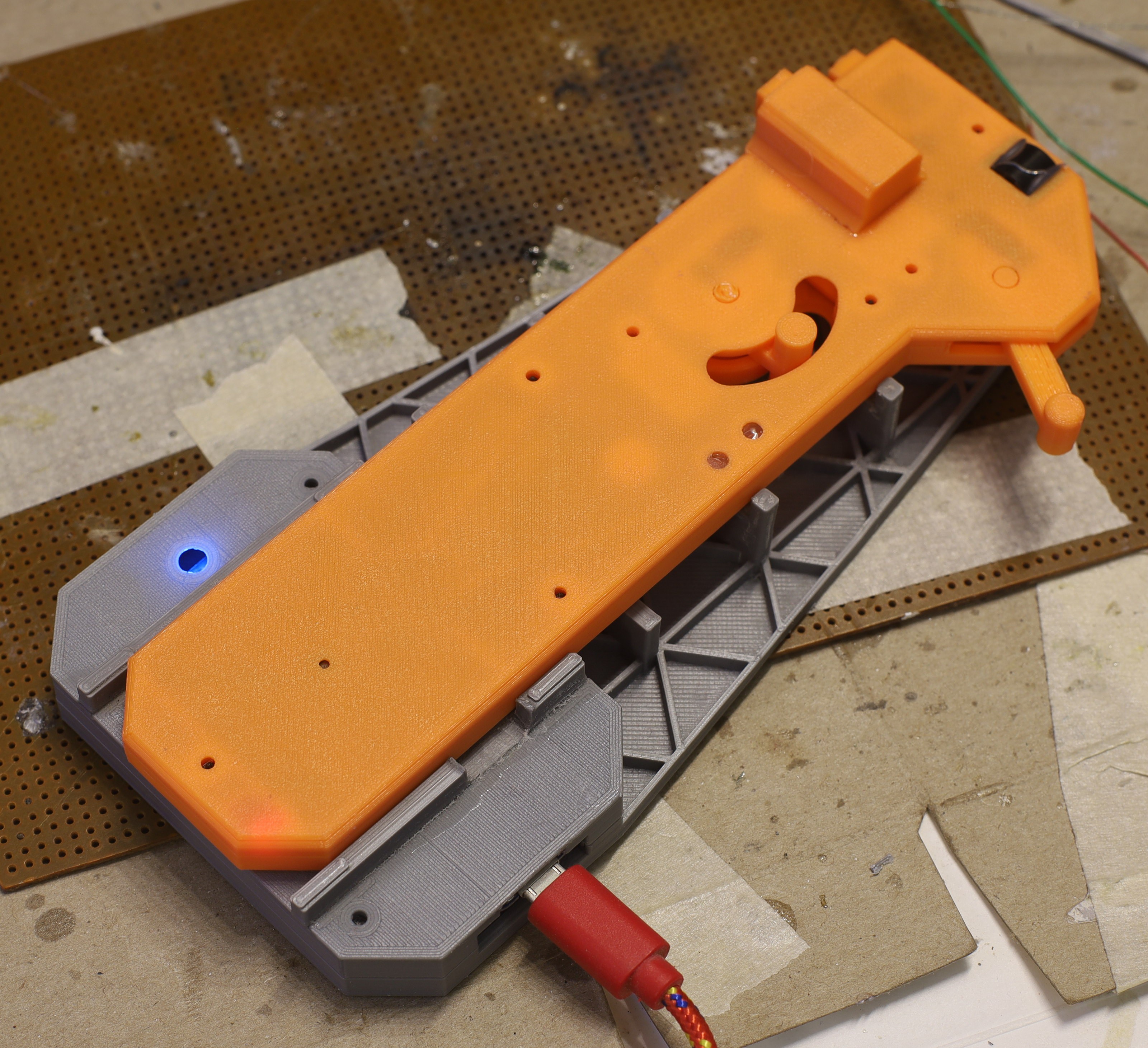
01/21/2023 at 23:06 • 0 commentsTo make the controller waterproof, the TPU sock eventually had to be permanent which meant updating the charging stand.
![]()
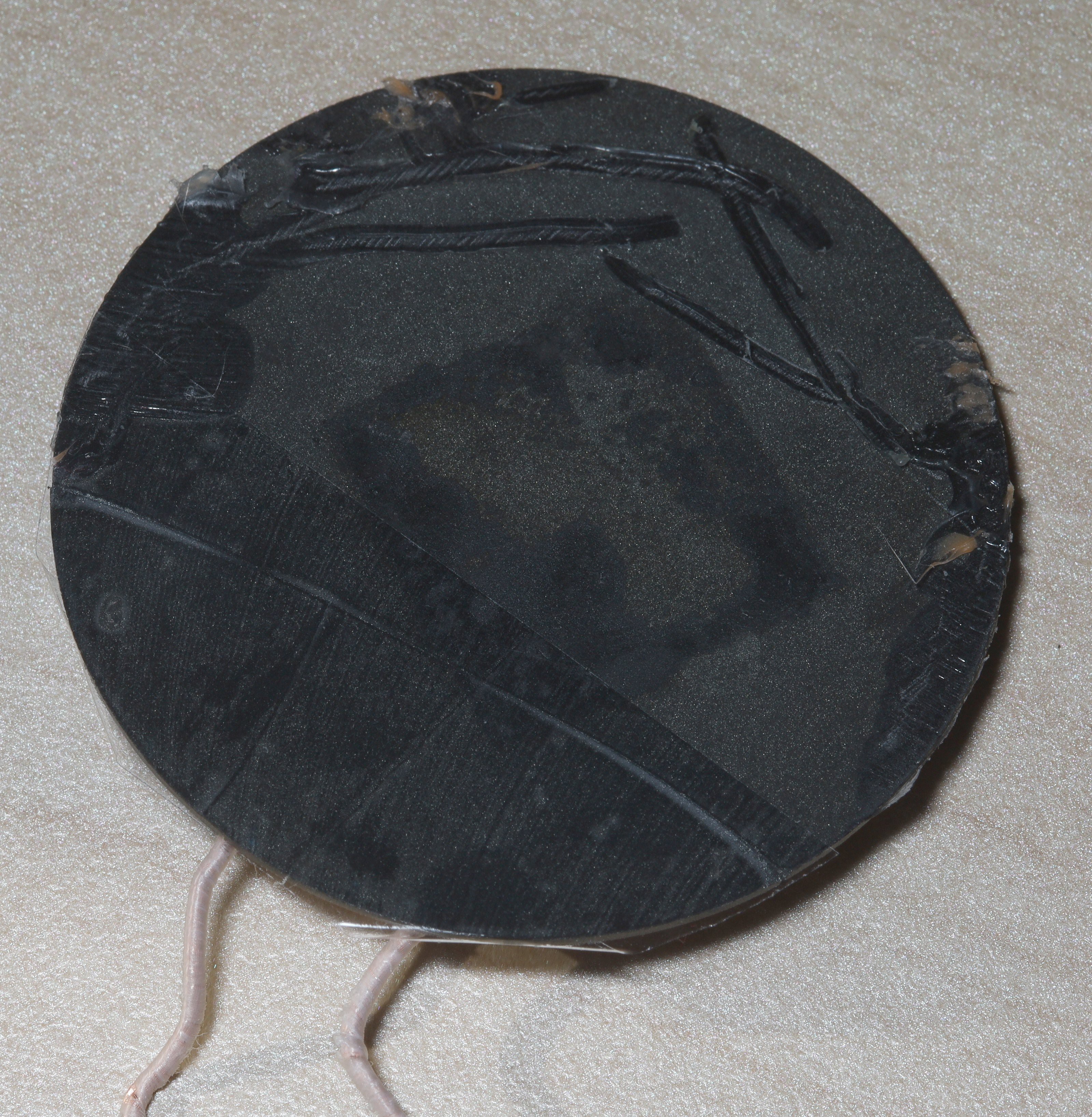
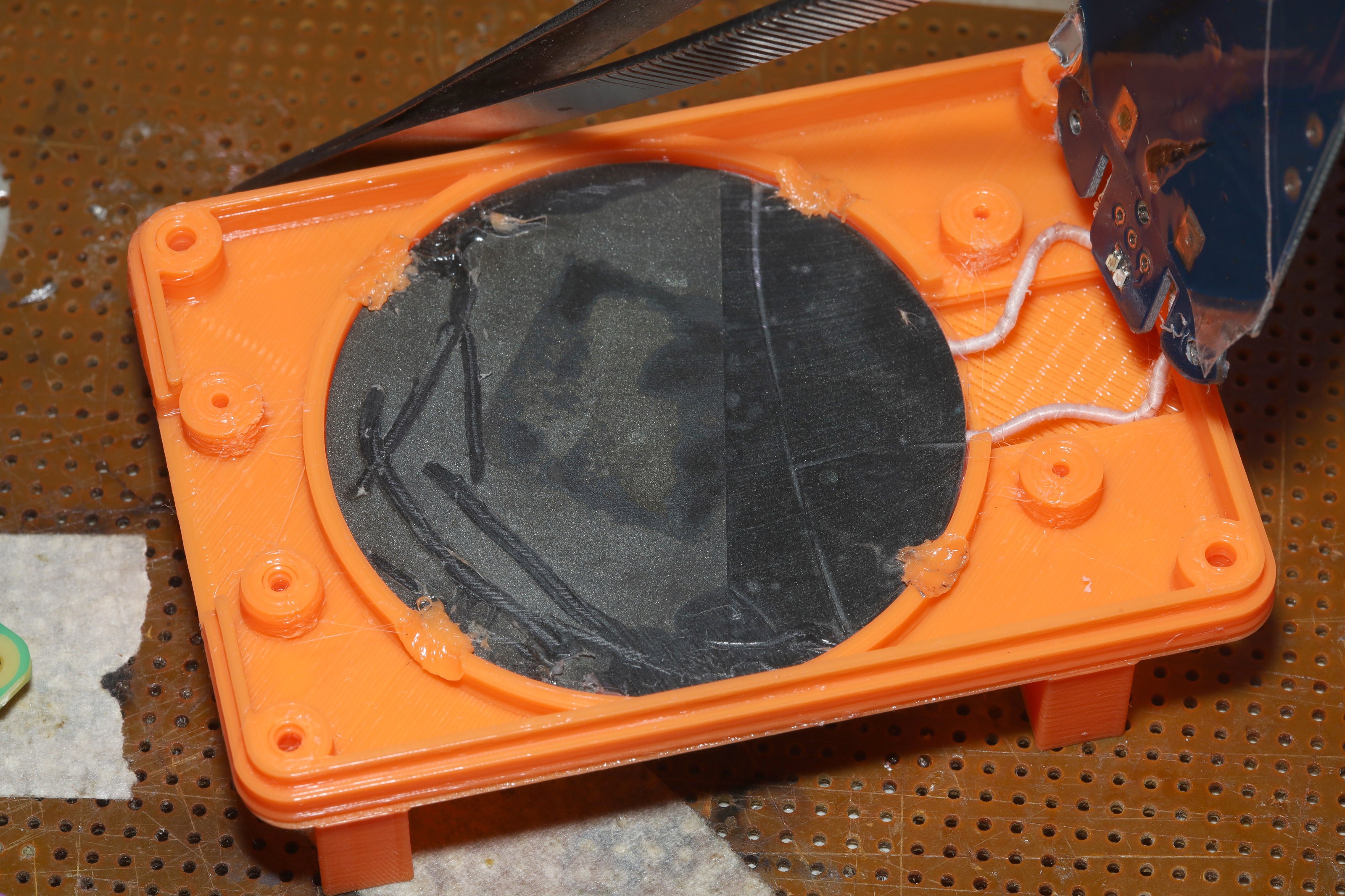
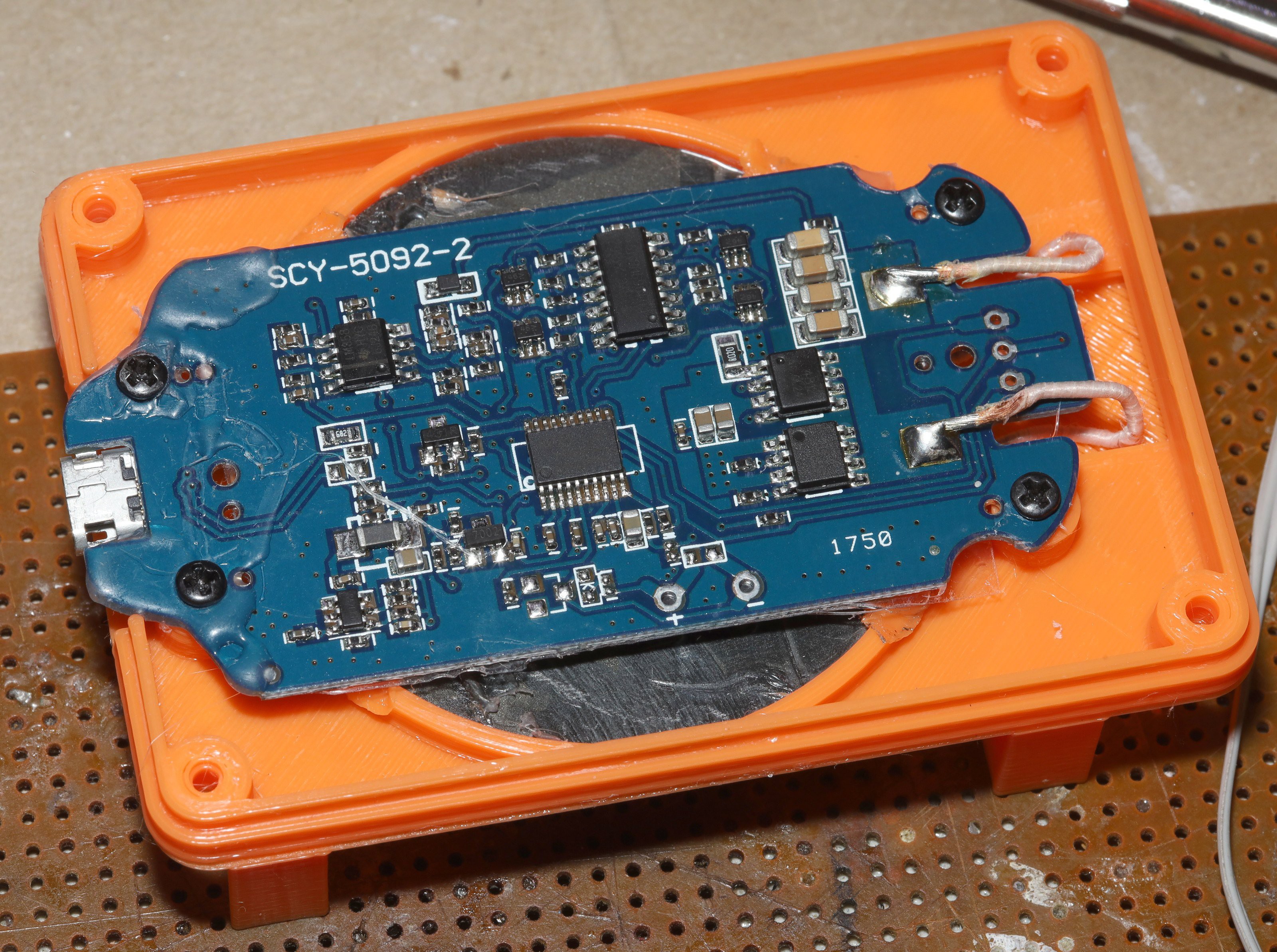
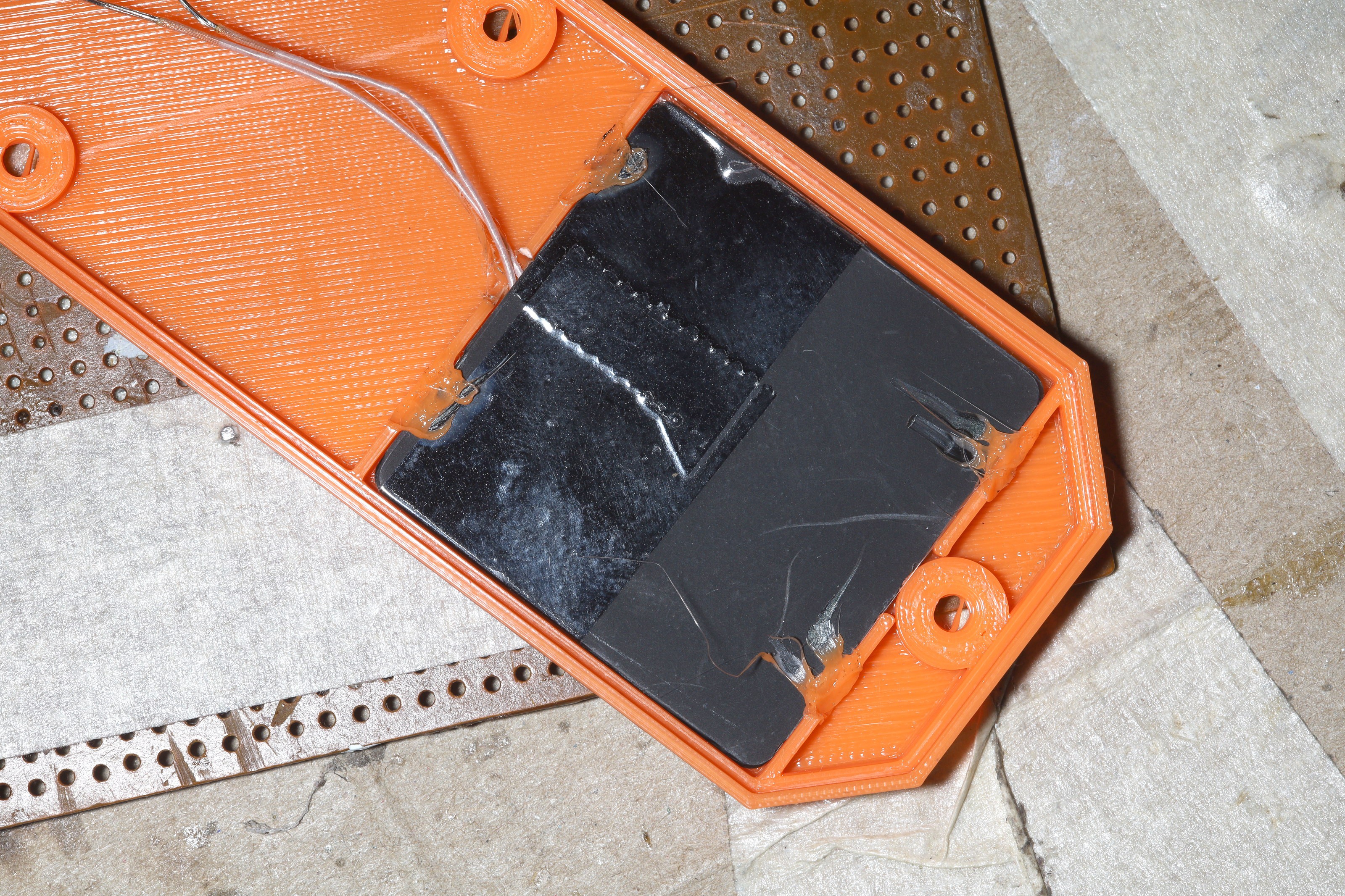
In this process, the charging inductor cracked. Those are really fragile. If the enclosure is too small or you try pulling it out when any PLA rivets are holding it in, it's going to crack.
![]()
![]()
![]()
![]()
The temptation is to press it when grabbing the charger. The problem is the new design fully exposes the inductor & nothing supports it in the middle. Below it is an air gap followed by the circuit board. At least Walmart has qi chargers locally at a reasonable price. The easiest solution is to not PLA rivet it & have some kind of foam press it out from the circuit board. It has a packing tape cover which could also prevent it from rotating.
![]()
![]()
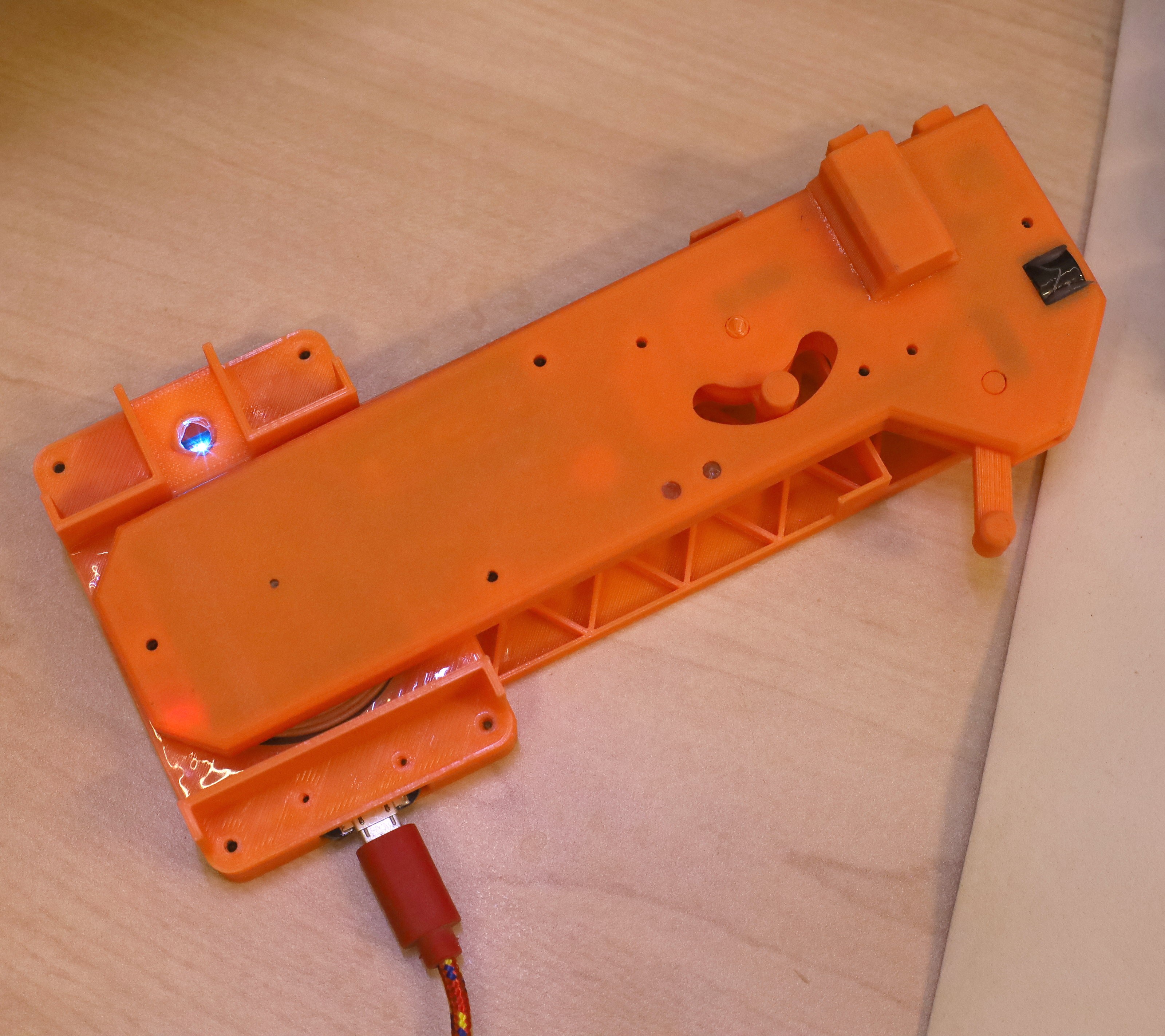
The lion kingdom's PLA riveting skills have improved to melting it with a brushing motion of the soldering iron rather than keeping the soldering iron stationary. This keeps it from sticking to the soldering iron. Then use the mark 1 lion paw to press it in position before it cools.With the sock now permanent, it would have to be translucent to see the charging LED.
![]()
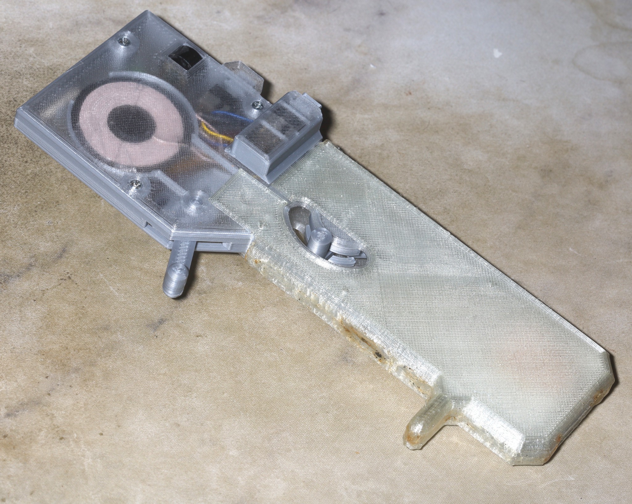
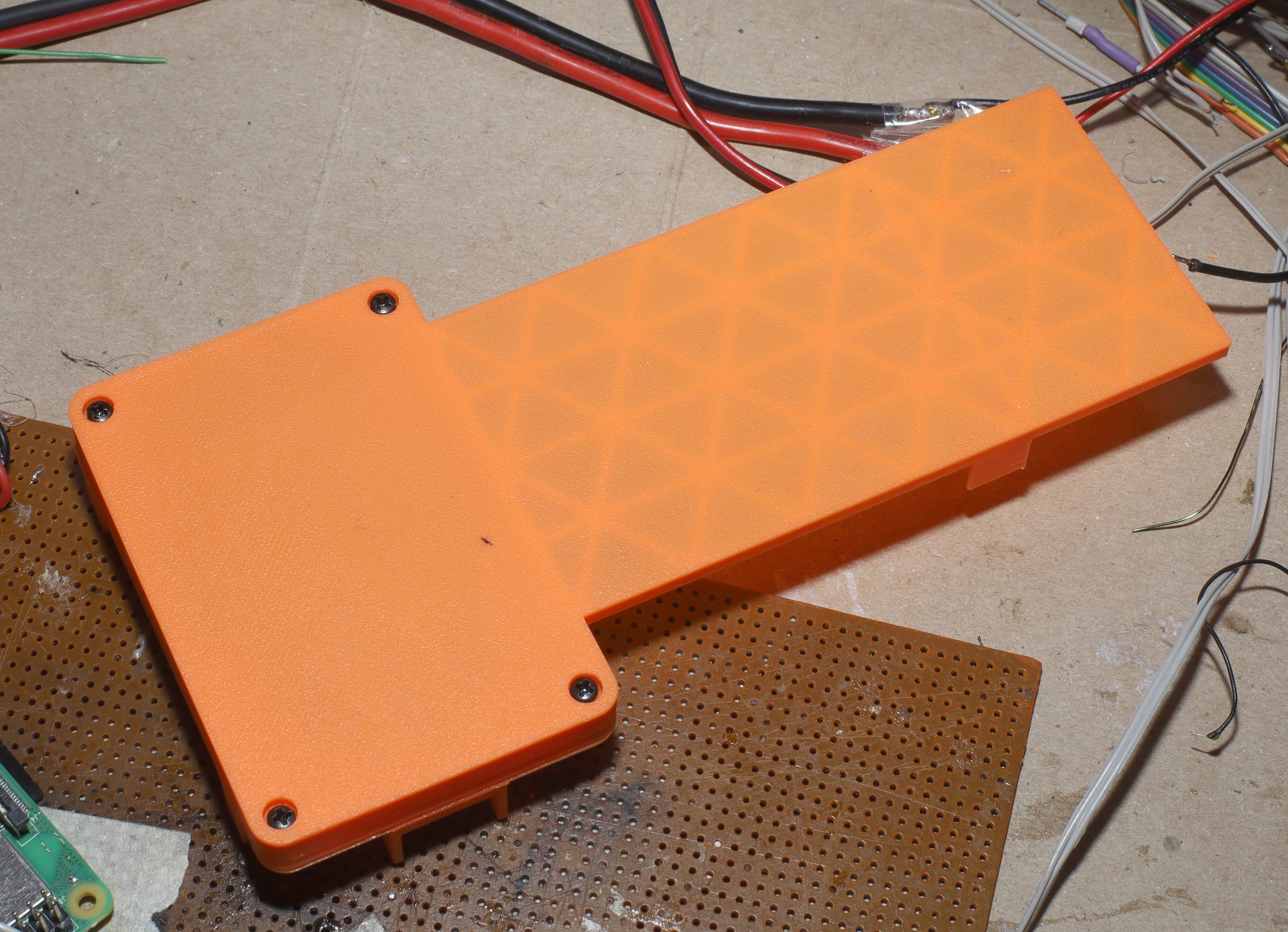
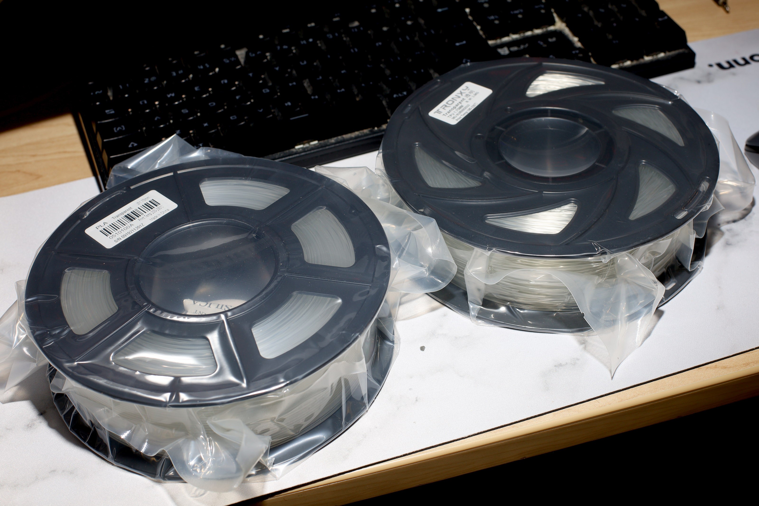
Translucent TPU & PLA entered the printer. The decision was made to retire orange PLA & hard black TPU. TPU is manely used for tires. The hard variant had very little use.
![]()
![]()
Panels which dominate lion prints come out a lot clearer than walls. It not obvious whether the filament came wet from China.
![]()
The charging LED is now visible.
-
New remote
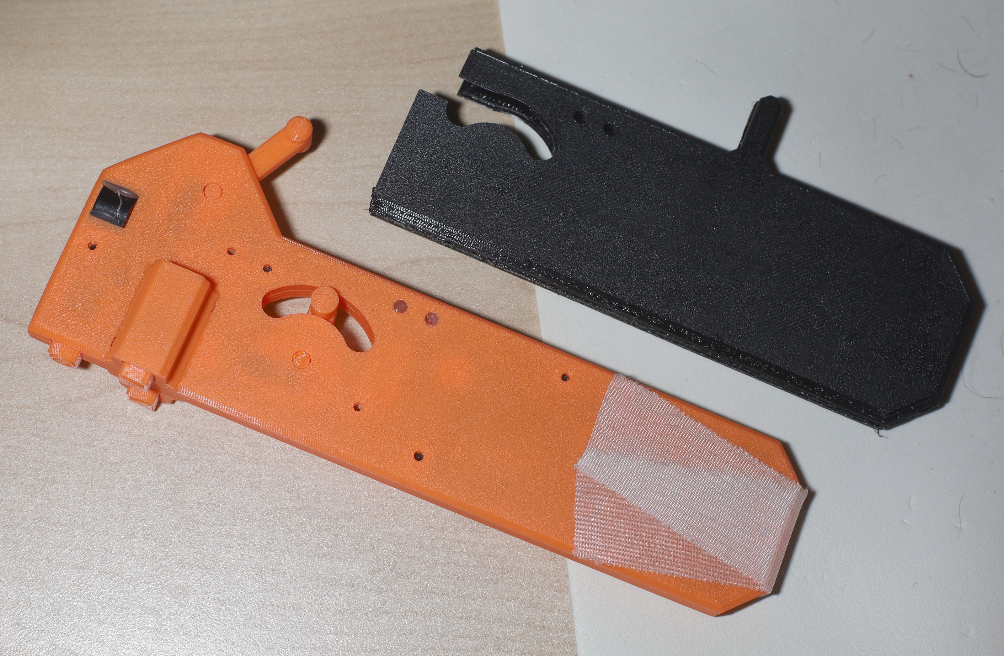
01/10/2023 at 07:30 • 0 commentsThe mane desires in a new remote were improved water resistance & replacing all the hot snot with PLA welding.
![]()
![]()
![]()
![]()
![]()
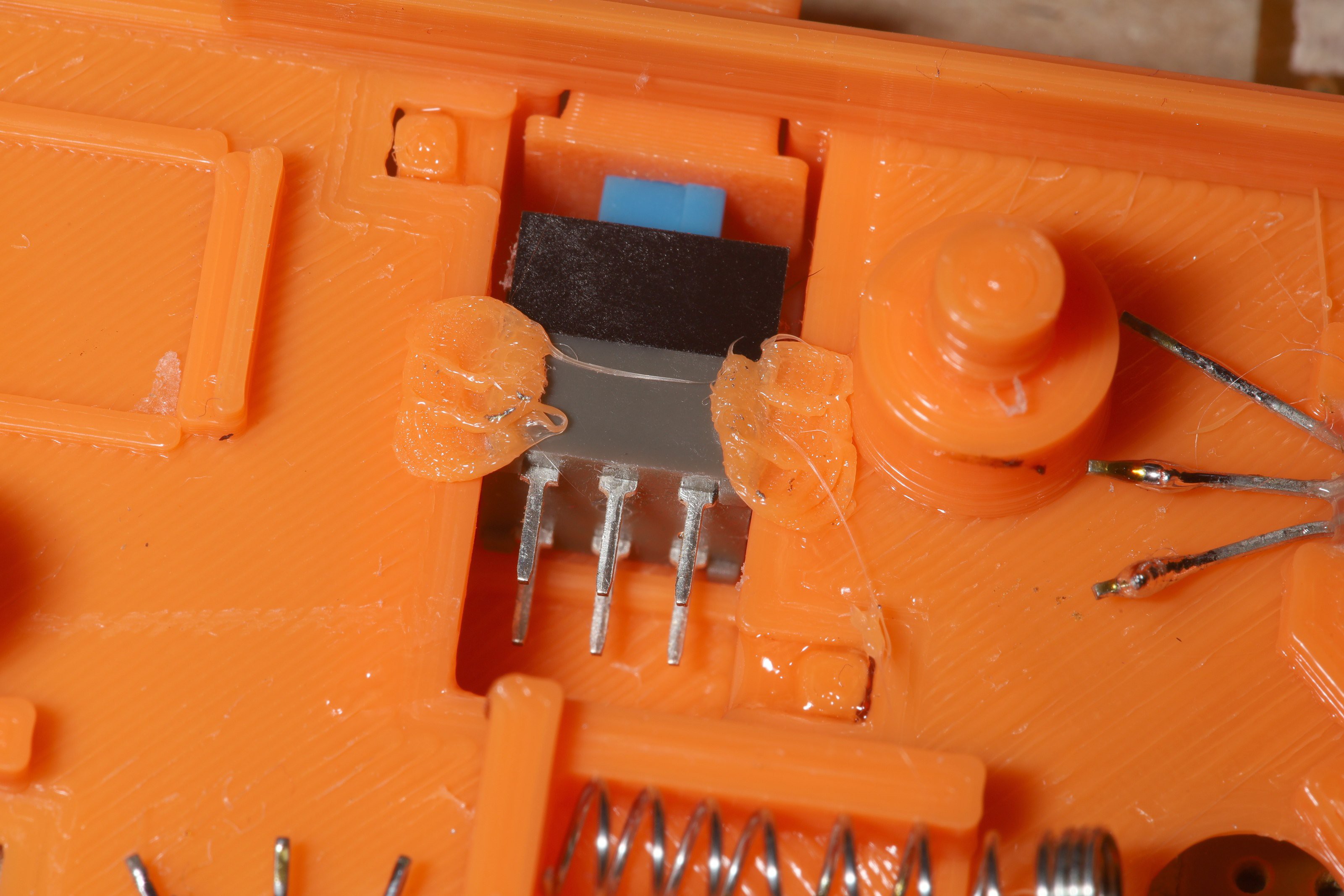
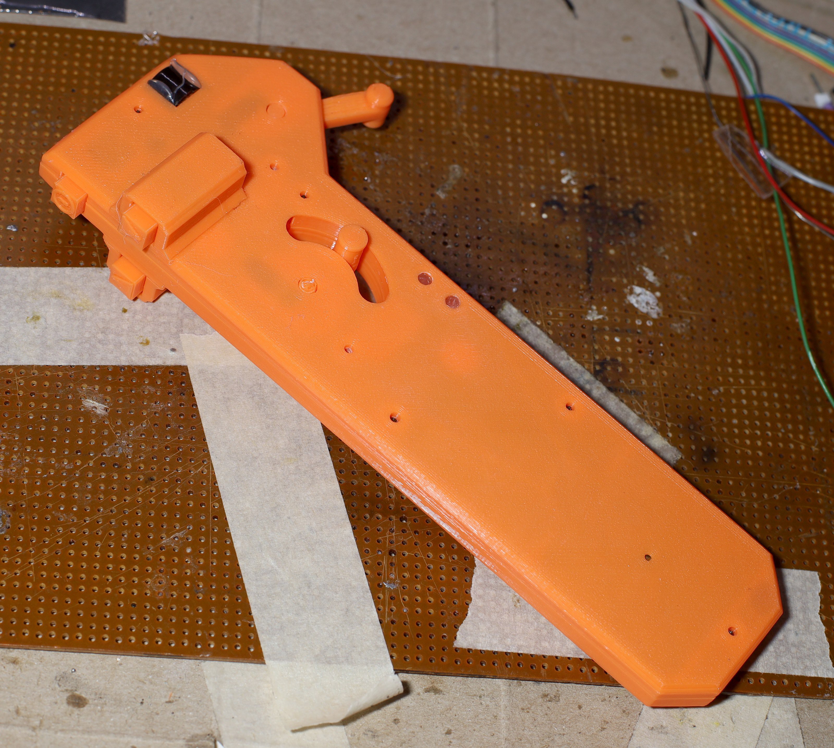
PLA welding was a successful failure. 1 switch still ended up needing hot snot. The best way to install the hall effect sensors was still to put a dab of hot snot down 1st, then press the hall effect sensor on, then flatten the dab. A dab of grease on the hall effect sensors still made a big improvement. Grease should not go anywhere else as it causes sticking. The only reason the joysticks get stuck is friction with the hot snot & grease.
A new trick with PLA welding was to melt the PLA with the iron but use the mark 1 lion paw to press it down. It adheres to the iron but not to the lion paw.![]()
![]()
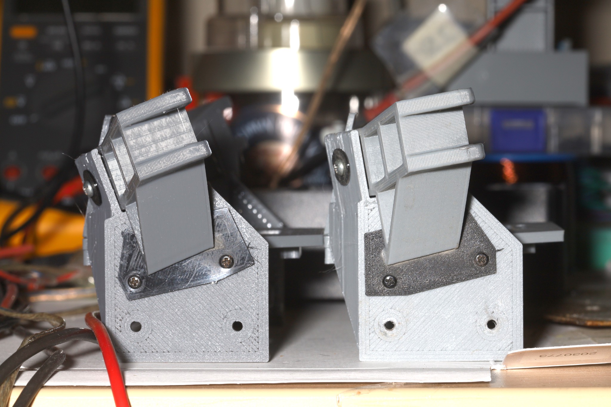
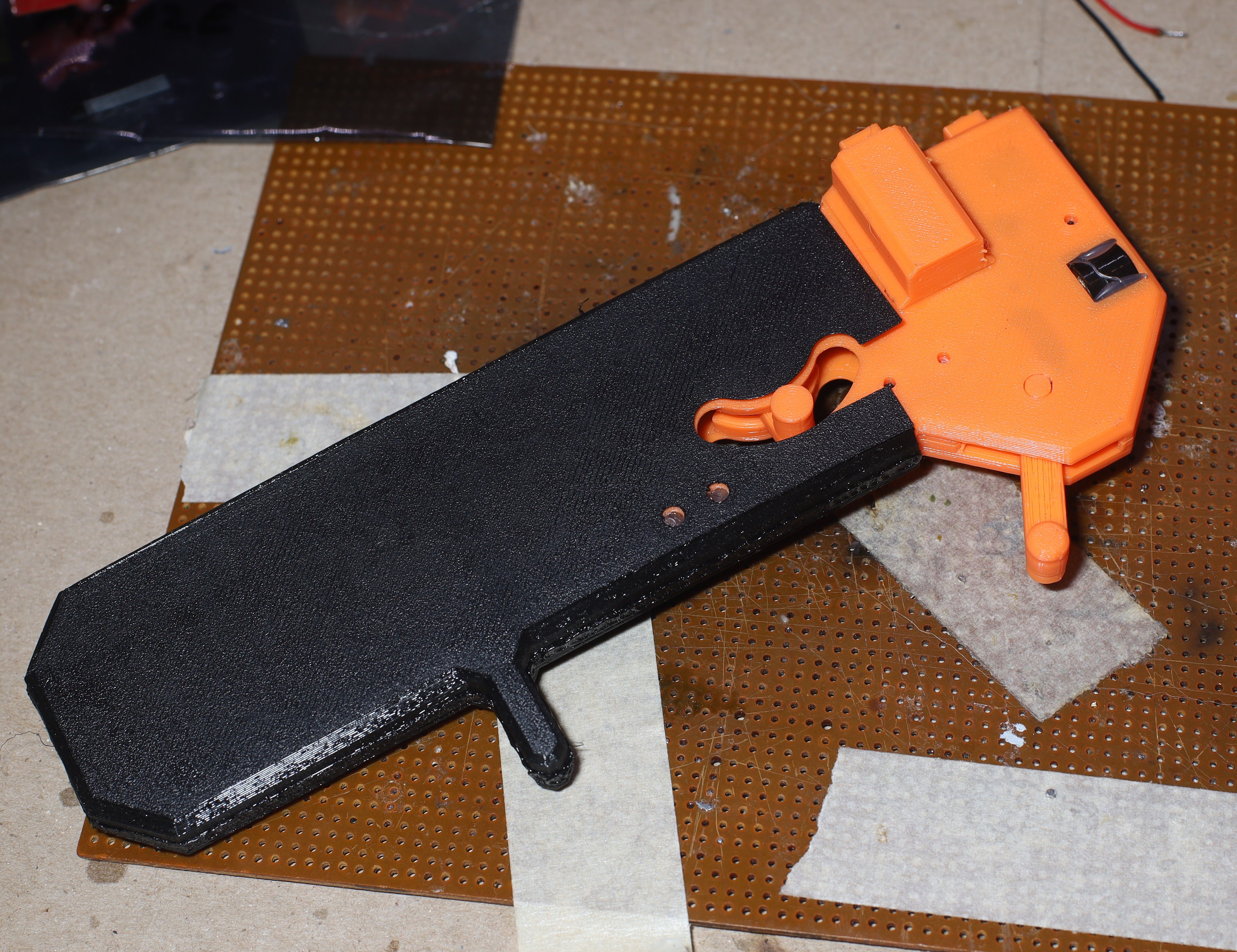
In the interest of water resistance, a sock covers the entire handle. The sock is removed for charging. If there's any evidence of how bad lions are at 3D concepts, it took a long time to realize the finger grip could be part of the sock. It actually holds water but doesn't have enough friction to stay on.
![]()
The mane problem is the welds don't go as deep as hoped. No point in using orange PLA if the sock is covering it. Low cost TPU is quite good for covers like this. Trying to stretch it over the steering stick was hopeless, so it got a cutout.
![]()
The leading idea to get it to stay on is taping the PLA to make it thicker. Other ideas are to print ridges inside the sock or make the sock narrower at a point. The problem with making the sock expand around the enclosure is welding the sock requires fitting it around the enclosure 1st. It would need a blank smaller than the enclosure just for welding.
Power consumption was 50mA, so a 260mAh battery is only going to last 4 hours on a good day. It needs the 400mAh battery which somehow fit in the last one. The 260mAh required a lot of coaxing to fit in there. If the radio constantly transmits, it burns 120mA. The transmit duty cycle is 5ms on & 35ms off. The PIC has to run at full speed for the sounds.
![]()
There's 1 heroic bodge wire to connect MISO to the radio. Despite every effort, the radio failed to initialize without several power cycles. The datasheet says Vdd needs 1ms ramp time. The LP2989 has a 5ms ramp when probed.
Merely cleaning the flux got it to start despite the LP2989 issue. Getting rid of 100uF of capacitance didn't do anything.
![]()
![]()
After fighting to get the sock over the LEDs, it was decided to put the LEDs inside the case & hot snot the LED holes shut. With orange PLA, the red charging LED shows nicely but the green transmitting LED is barely visible. Transparent PLA would be ideal, but there's a real need for white PLA for an LED diffuser. Nylon paper might work as an LED diffuser, which would make transparent PLA the better deal for fabrication. LEDs that diffuse through the enclosure should be a bigger part of all designs.
The hall effect sensors are 1.3mV/G so they never saturate. There is a desire to make the handle narrower to compensate for the sock size. The steering lever should be either square or longer to compensate for the sock.