lion mclionhead
-
Captive locknut motor farsteners
09/29/2021 at 04:45 • 0 comments![]()
![]()
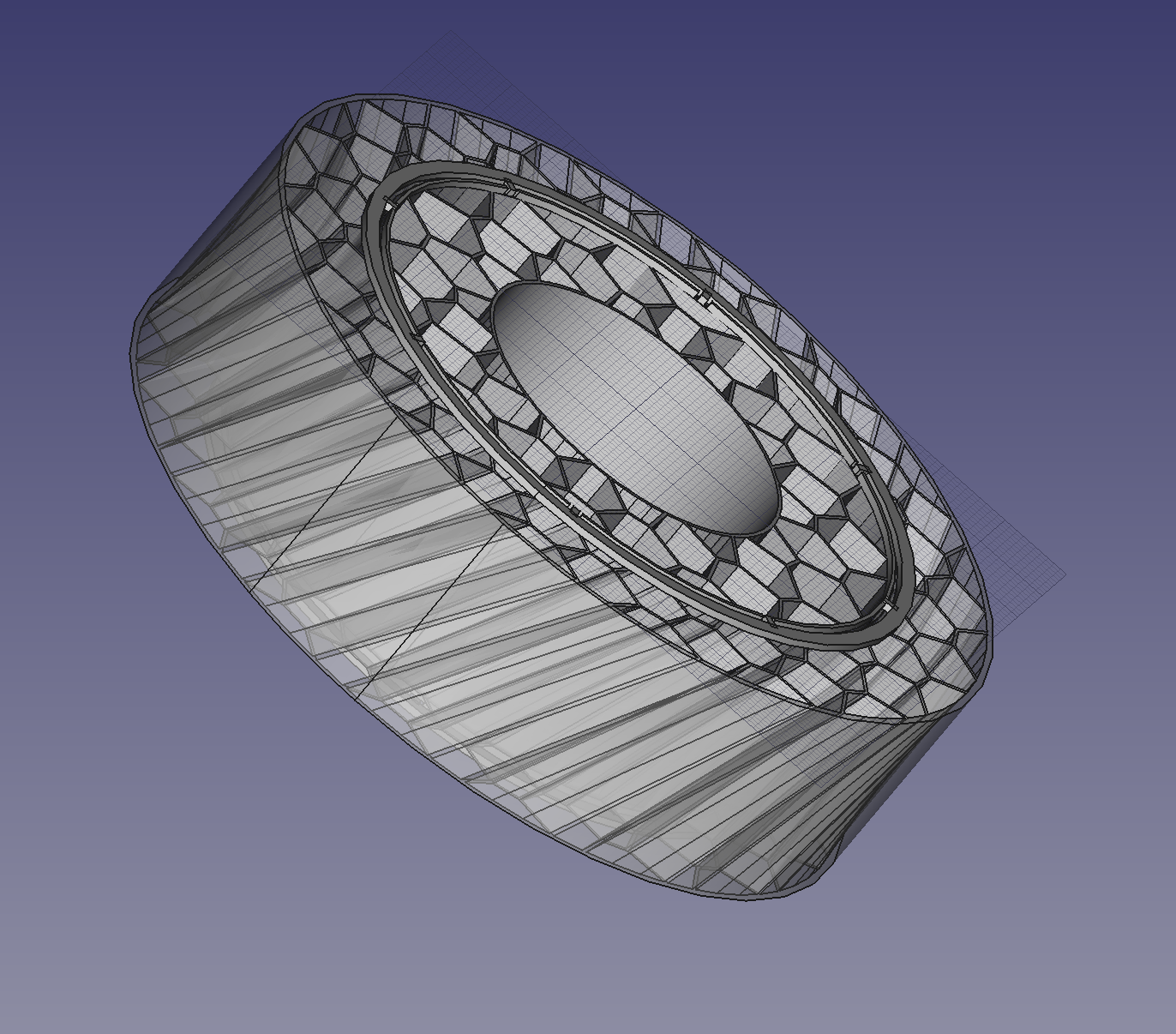
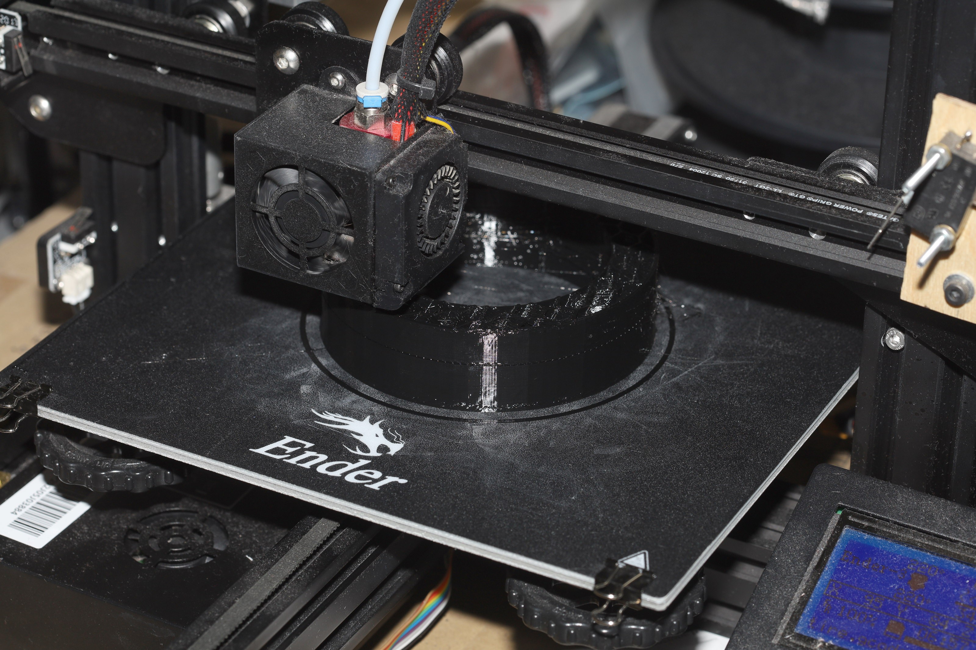
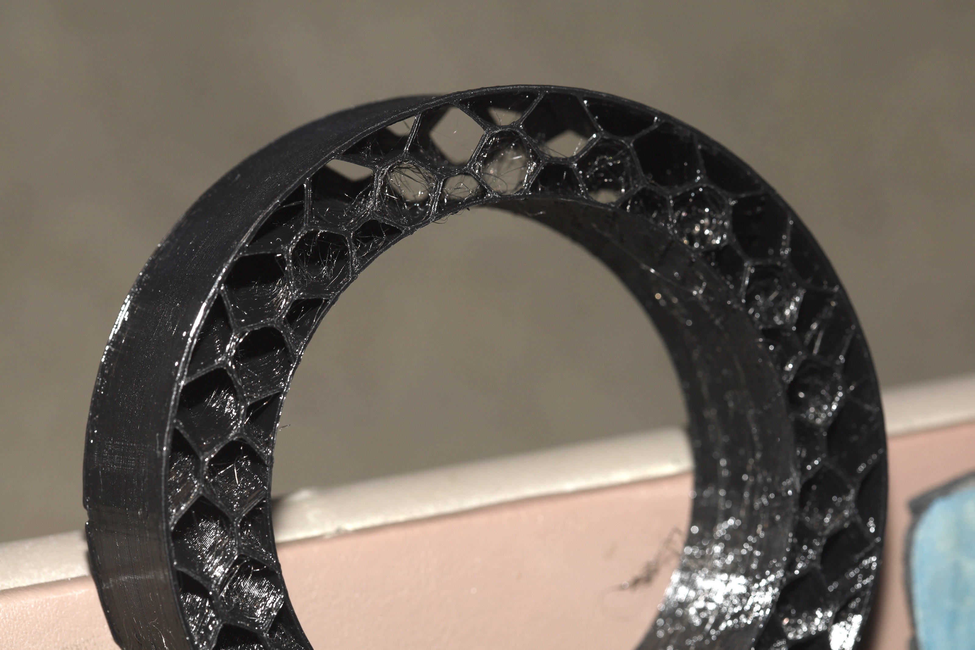
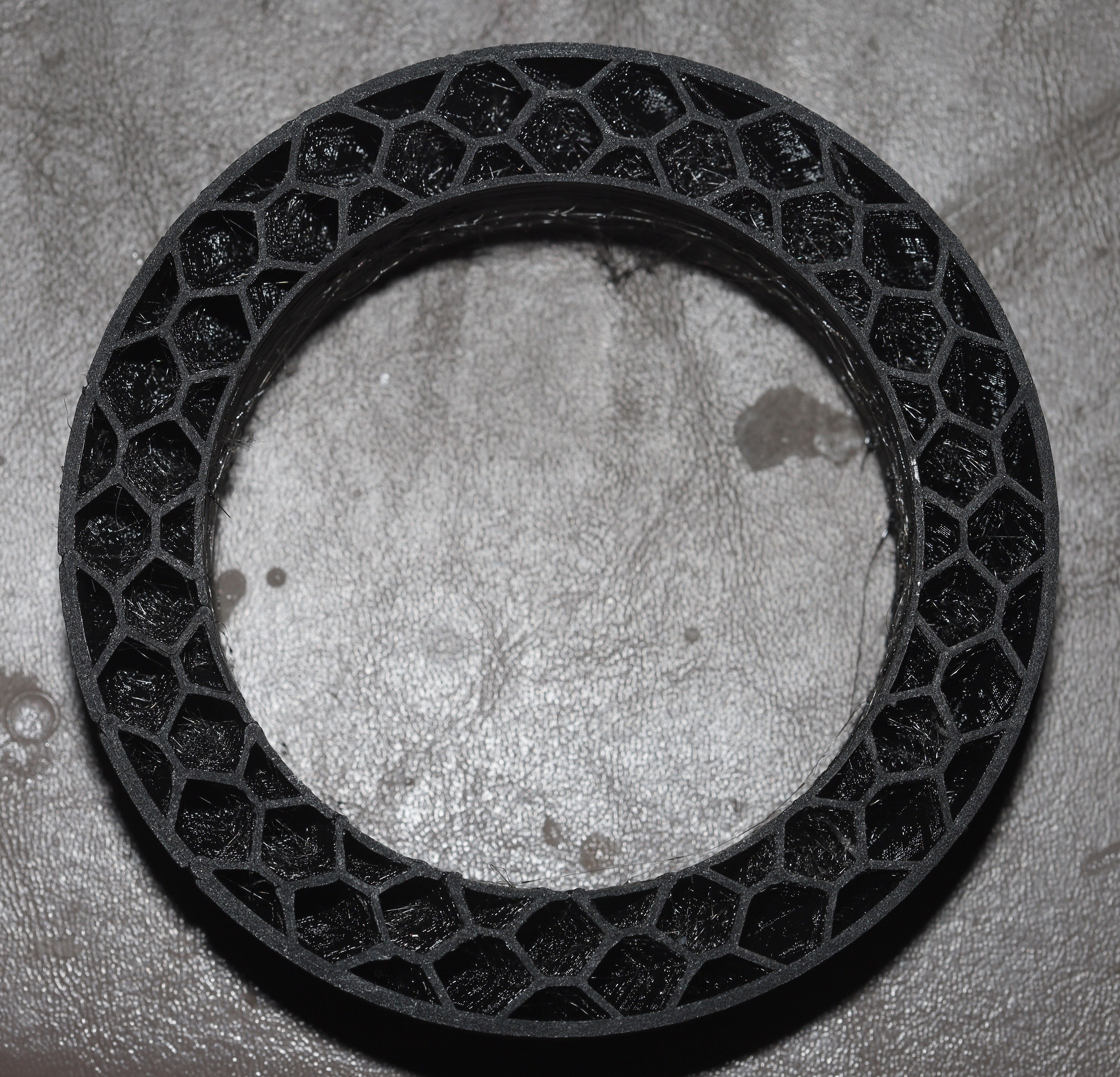
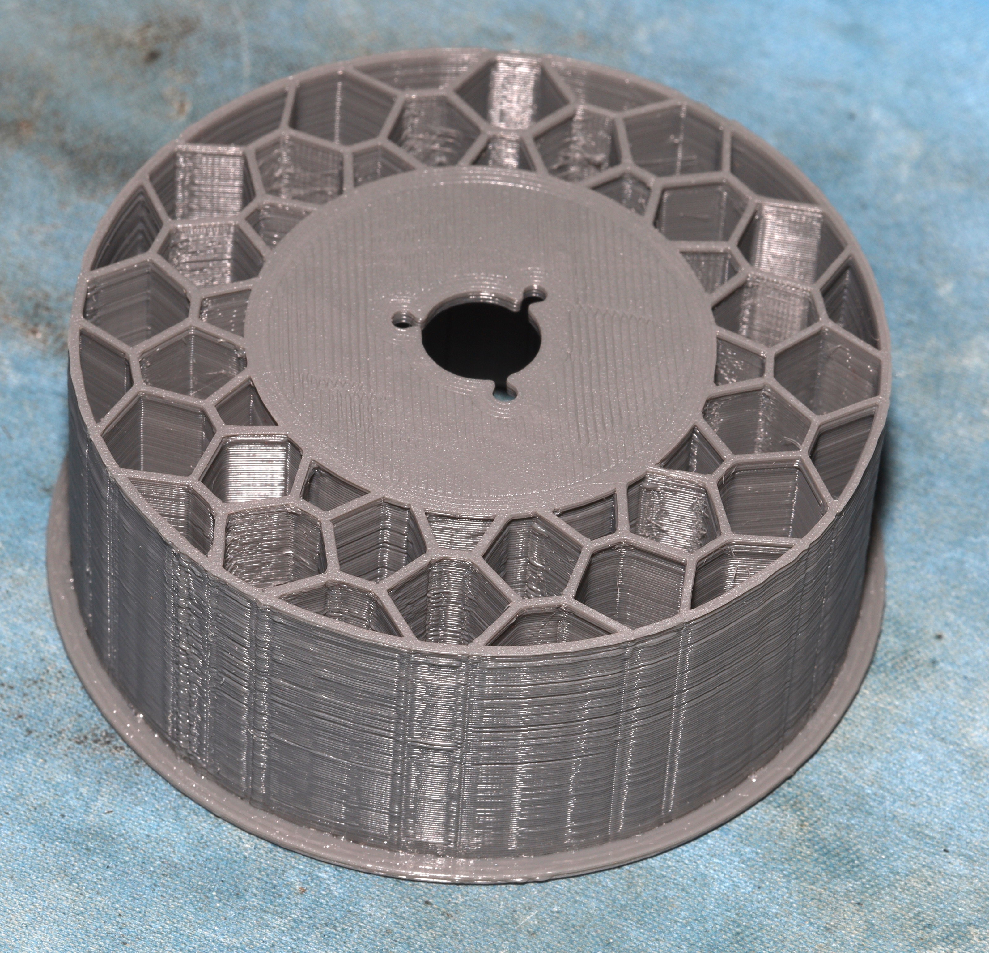
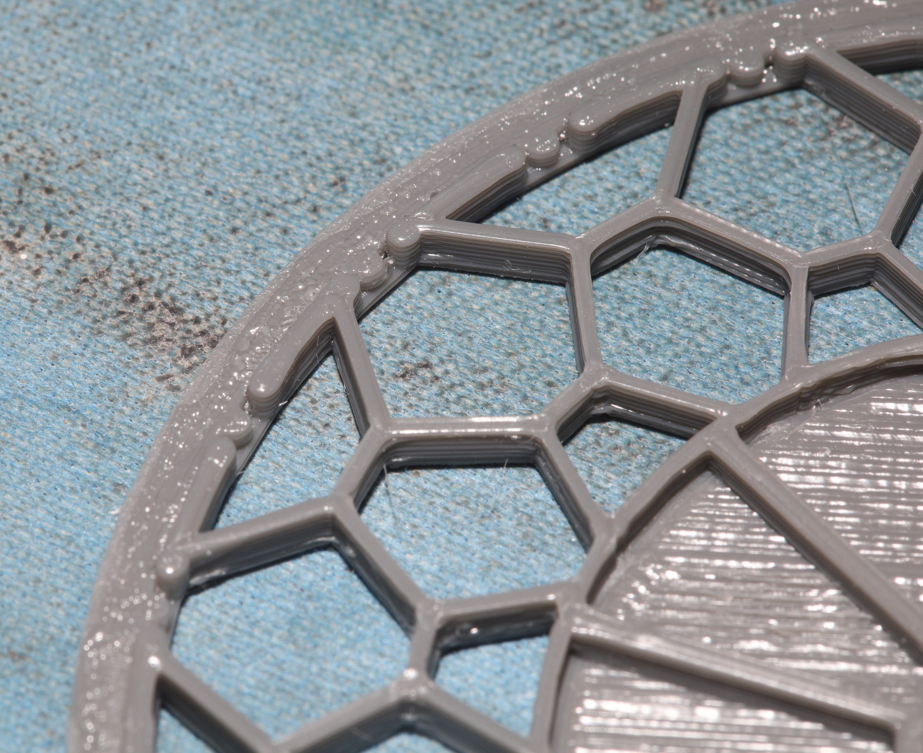
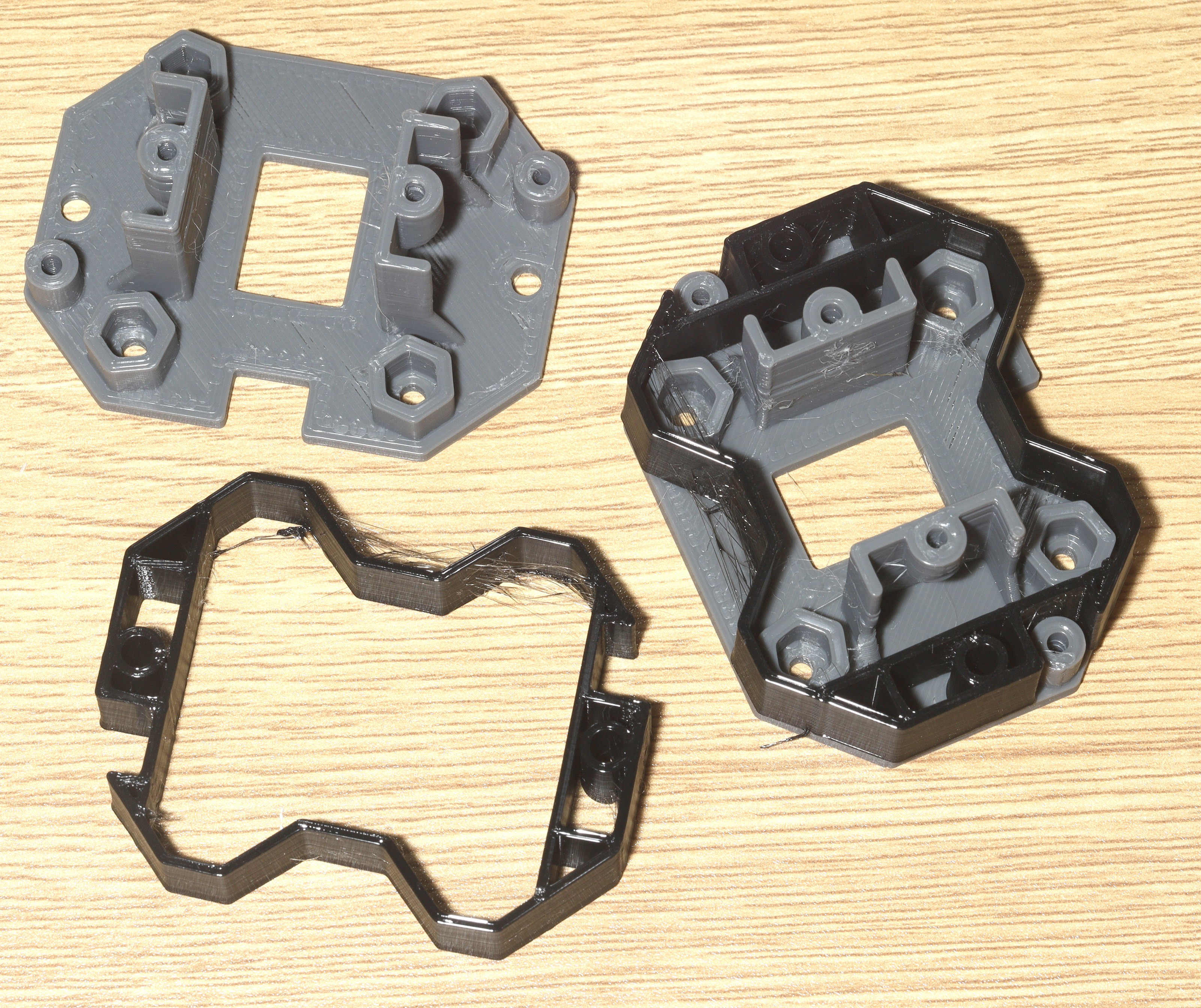
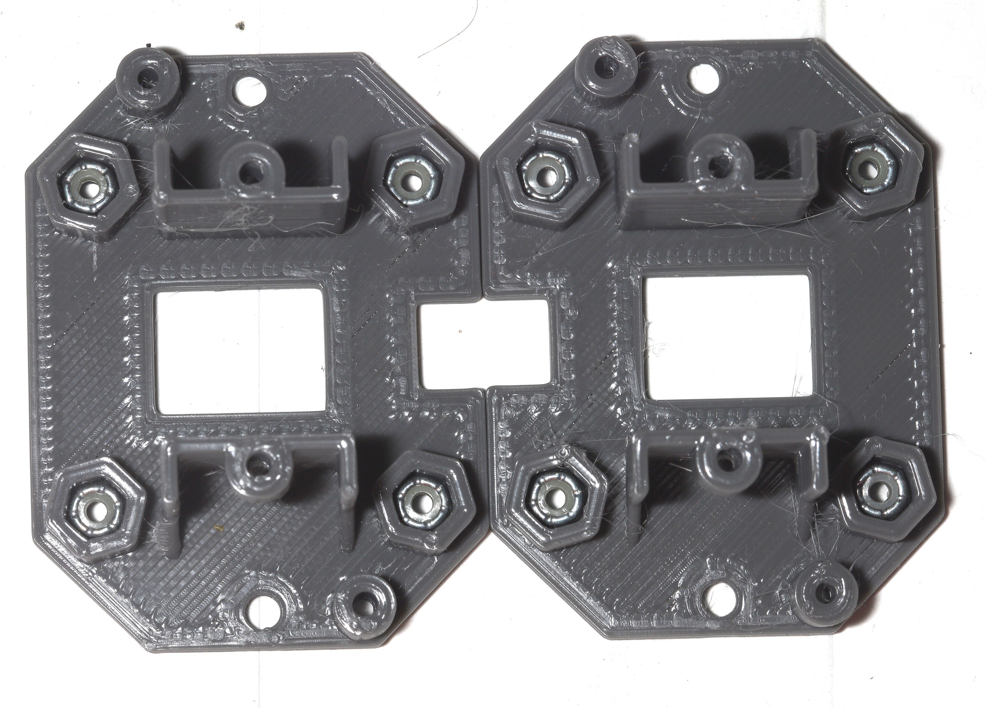
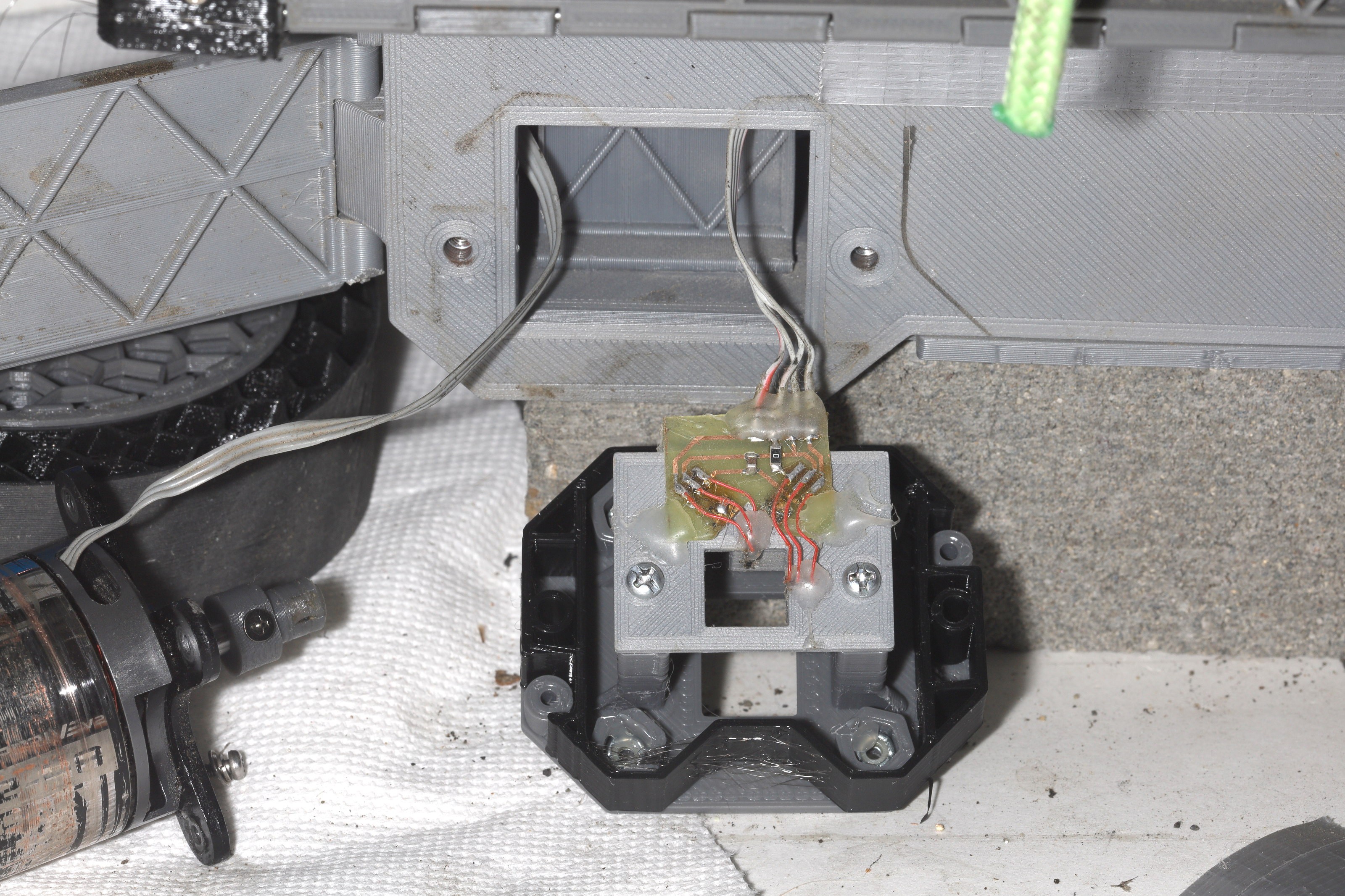
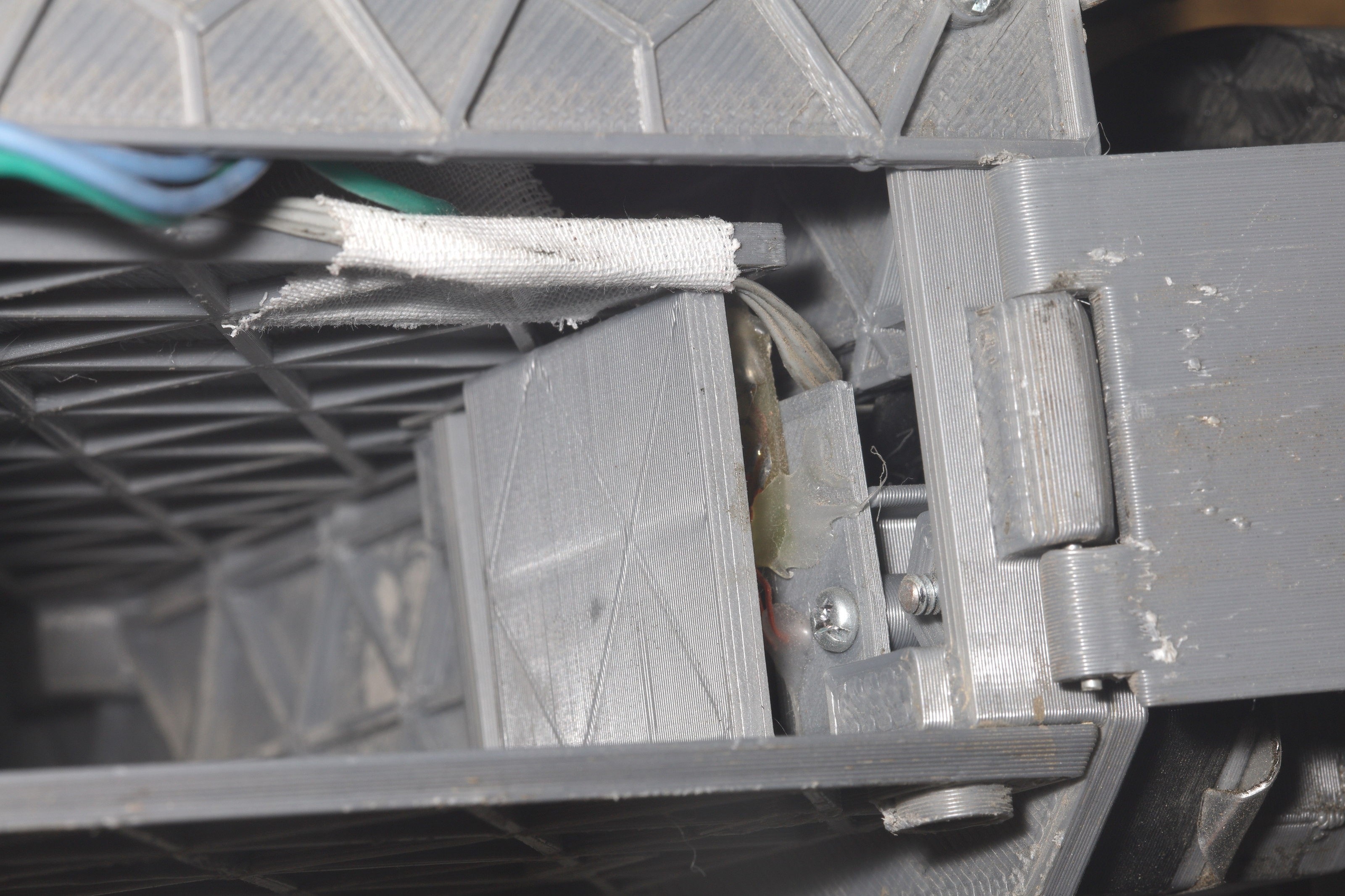
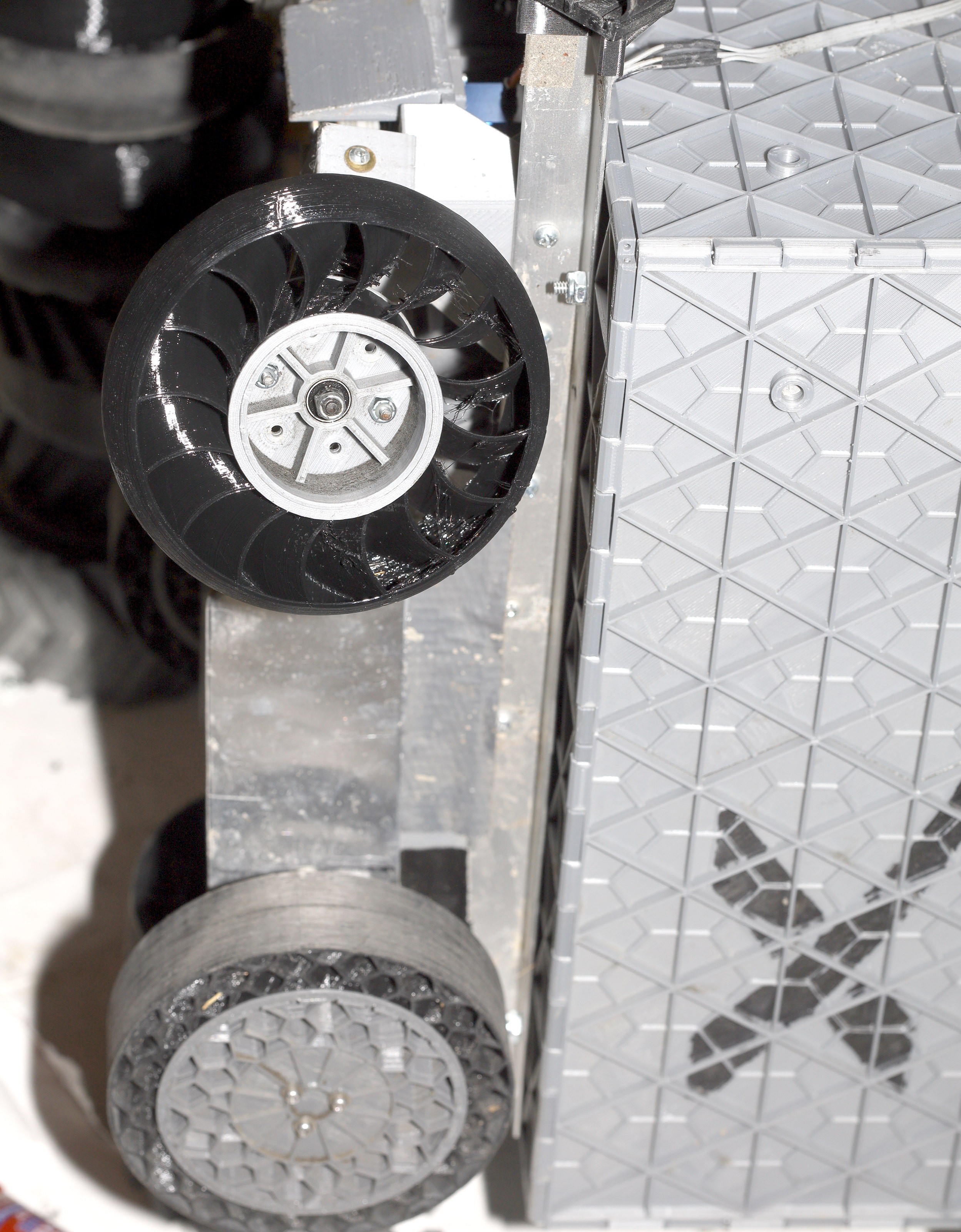
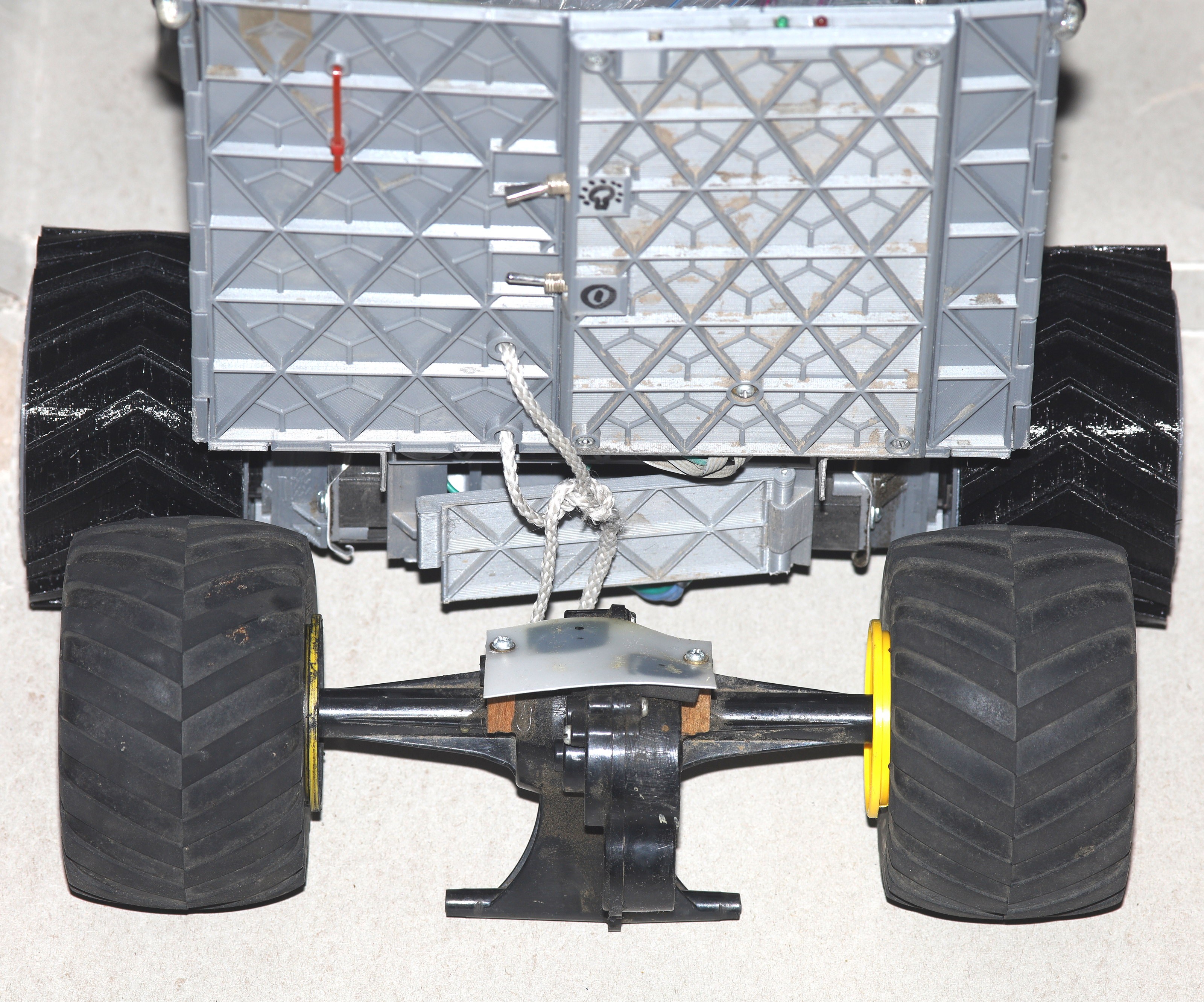
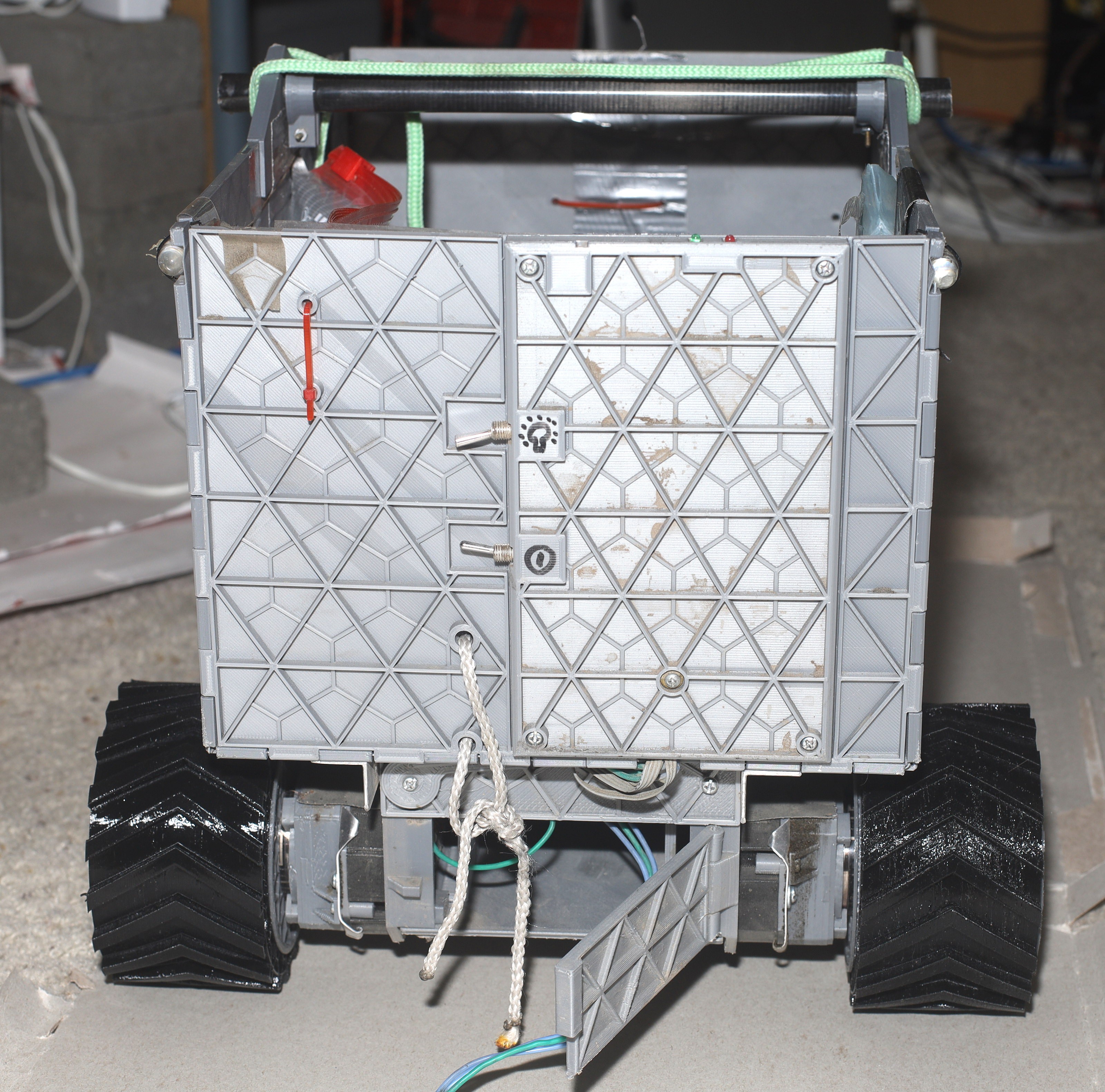
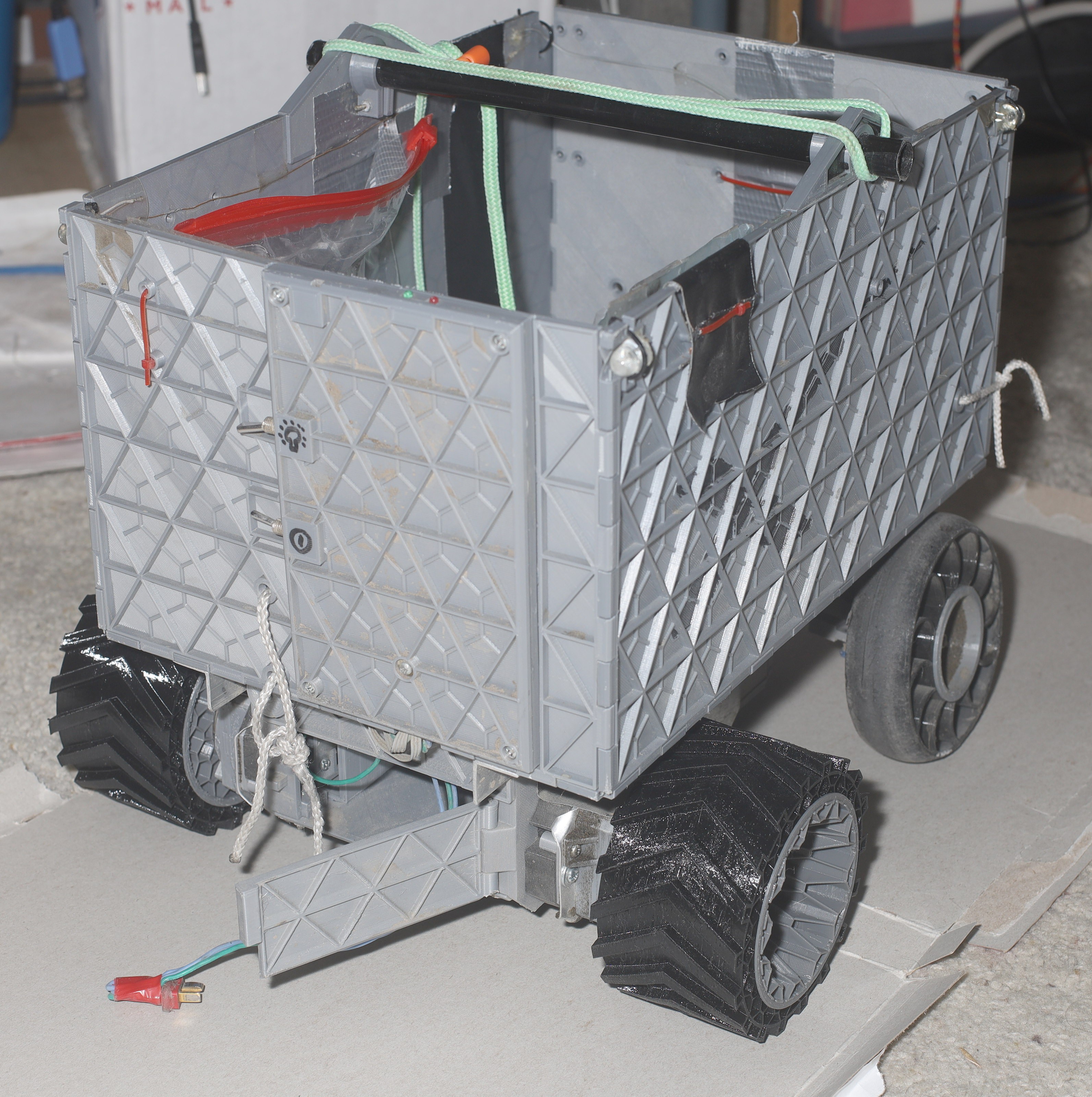
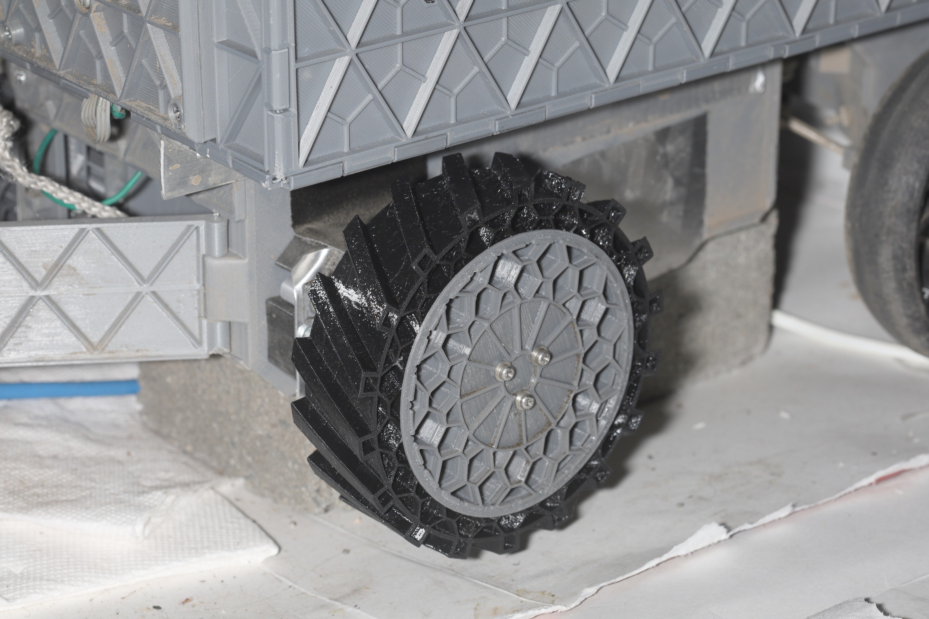
It occurred to the lion kingdom that the use of self tappers as load bearing farsteners has been a disaster of biblical proportions. The latest thinking was to use captive 4-40 locknuts & hot glue to farsten the locknuts. The new motor module still managed to have acceptible tolerances with the .8mm nozzle.
The hot glue actually seemed to work. If it got in the way, it managed to be compliant enough for the screw to not push it out. The captive nut walls are still too thick. The nuts aren't going to break PLA. It's going to compress.
The mane unknowns are if the 4-40 bolts are going to stay on as well as the self tappers did & if the motor will find another way to stall when it overheats or if it'll just destroy itself.
![]()
![]()
![]()
![]()
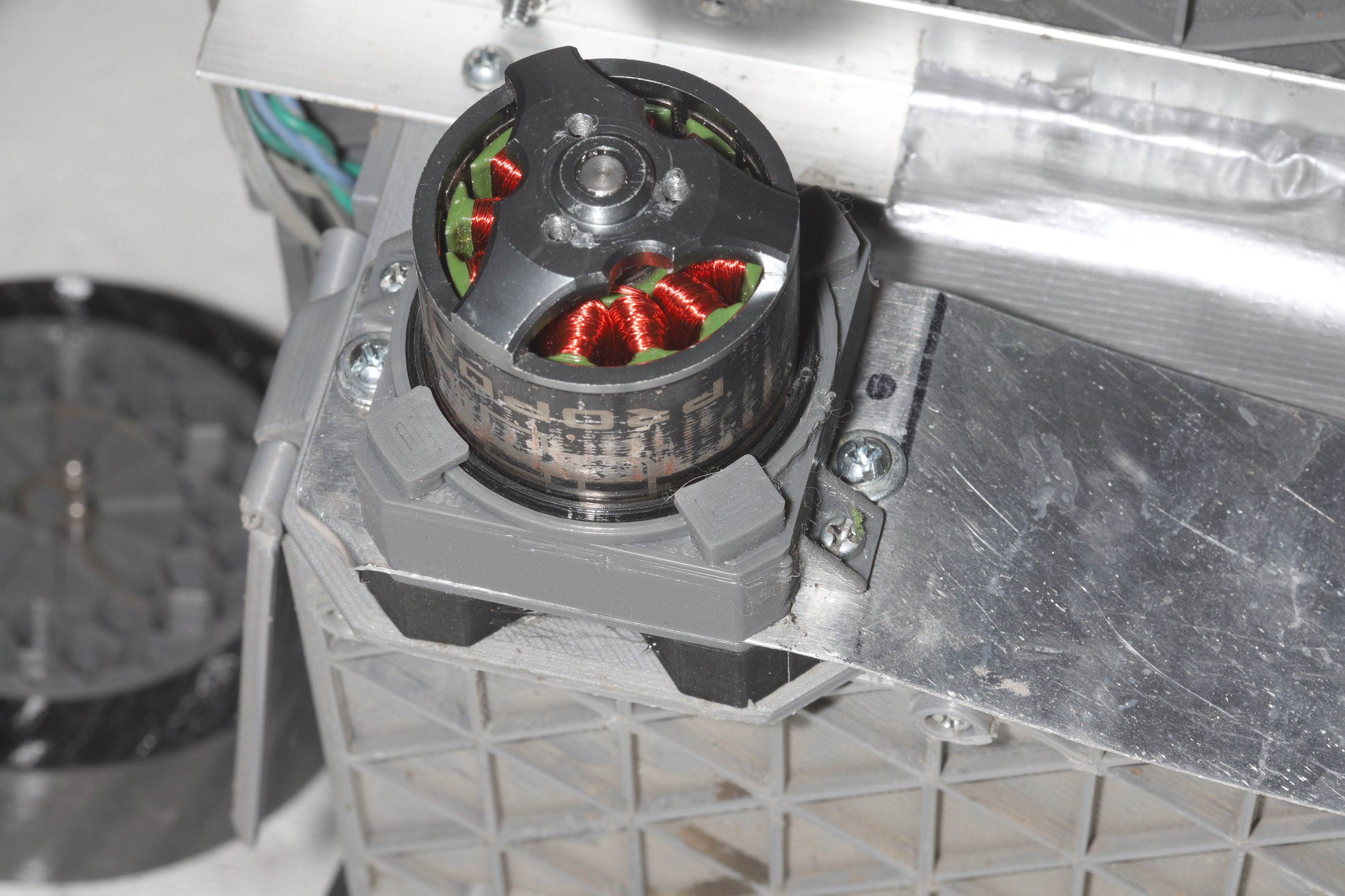
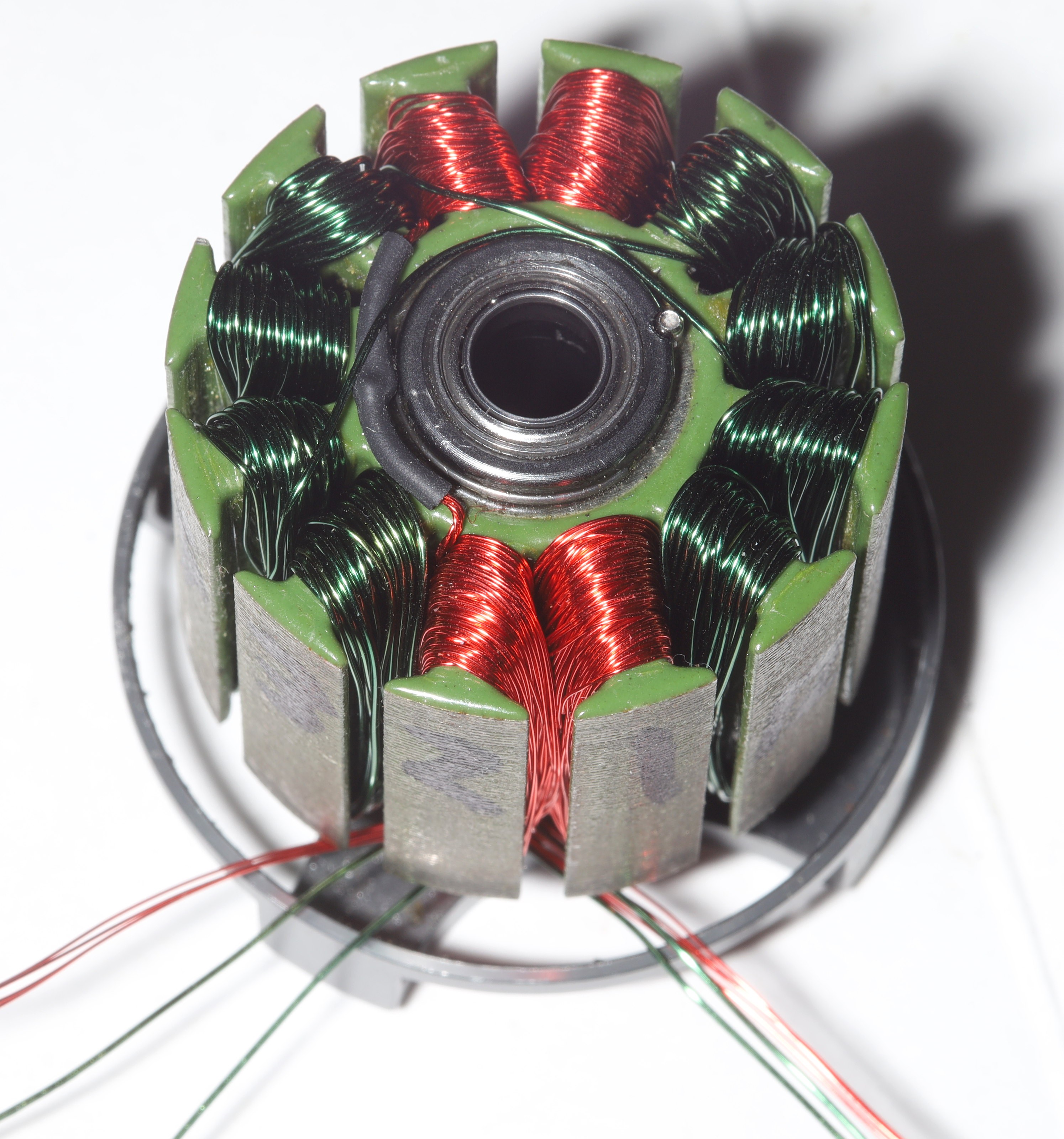
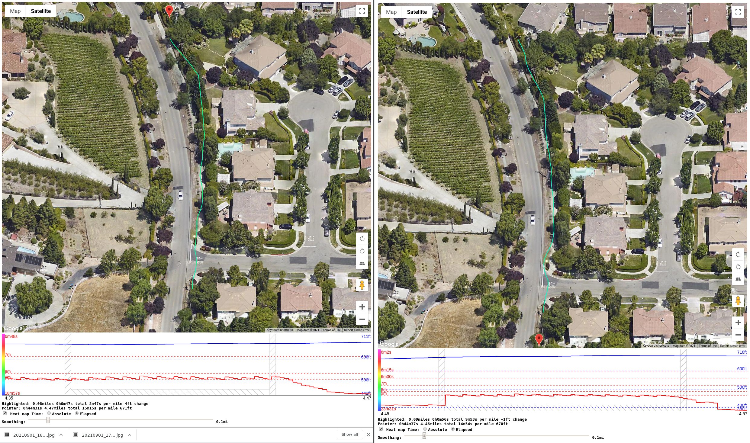
After 3 miles with the locknut motor plates, the right motor let out the magic smoke. It manifested itself as a loss of torque despite accurate commutation. There was no evidence of the encoder failing, the locknuts getting loose, a stall, or debris. The motor just stopped providing torque & overheated after successfully ascending part of a hill.
![]()
![]()
![]()
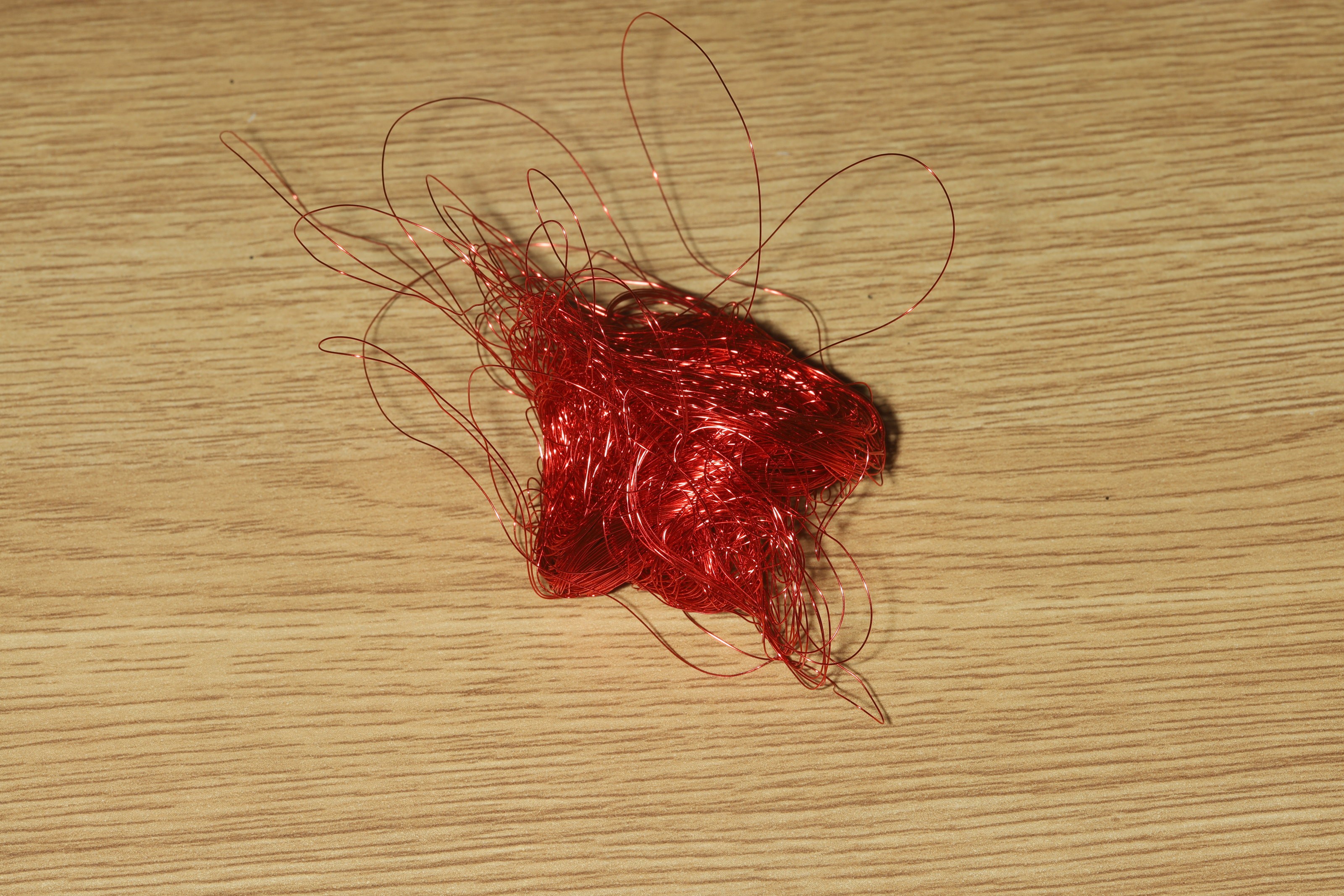
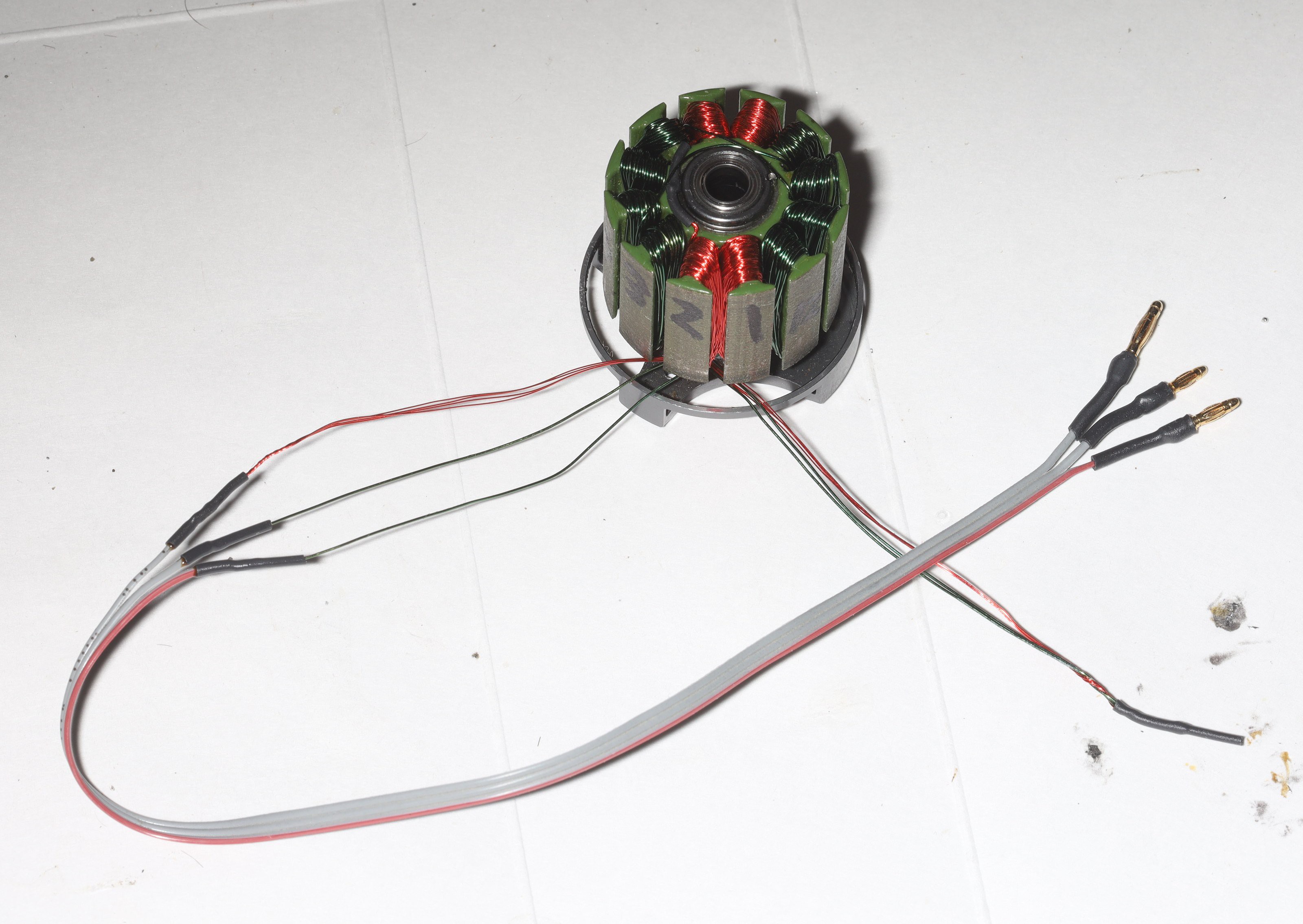
Decided to rewind it over the next 4 hours & see if the problem happened again. Sadly, the 32 AWG got tangled. If 32 AWG gets tangled, the only solution is to cut it off & throw it away. It can't be untangled. Ended up doing 2 of the fields in the last of the 26 AWG & ordered another spool of 26 AWG since there is going to be a lot of magic smoke.
What's probably going to happen is a switch back to self tappers. There was no evidence of the locknuts causing the failure, but they were the only explanation. The best explanation is the rebuild was slightly off, causing the encoder to miss just enough to suck more power but not stall. The overheating would have caused the motor to stall before burning up, with self tappers. The locknuts allowed it to overheat without stalling until it died.
Chinese direct drive motors don't have these problems because their sensors are epoxied into solid steel & their motor mounts are solid steel to suck away any heat.
So 8.7 miles with the latest motor rewinding sucked a whopping 190mAh/mile. Solid core 26 AWG might actually be more efficient than quad 32 AWG. The best explanation lions have is the skin effect. In a high frequency PWM application, skin effect causes more resistance as wire diameter decreases. Laminated quad 32 AWG has 4 times more surface area than solid core 26 AWG, so the quad 32 AWG would have a lot more resistance than solid core 26 AWG. You'd think it would matter more for kilometers of wire & megahertz than a motor winding.
It's become clear that the motor encoder is getting knocked out of alignment & the reason probably isn't loose cables snagging it. Lacking any reason, the idea of farstening thermisters to the motors is gaining traction. In 1985, thermisters might have been available in every corner Radio Shack, but in the future they're a little hard to come by.
Daily repair work turned to a failure of the happy meal controller to charge anymore. It had salt water damage around the battery management chip, so the latest clamshell still isn't repelling water.
-
MHPS2285 vs MHPS2266
09/28/2021 at 04:40 • 0 comments![]()
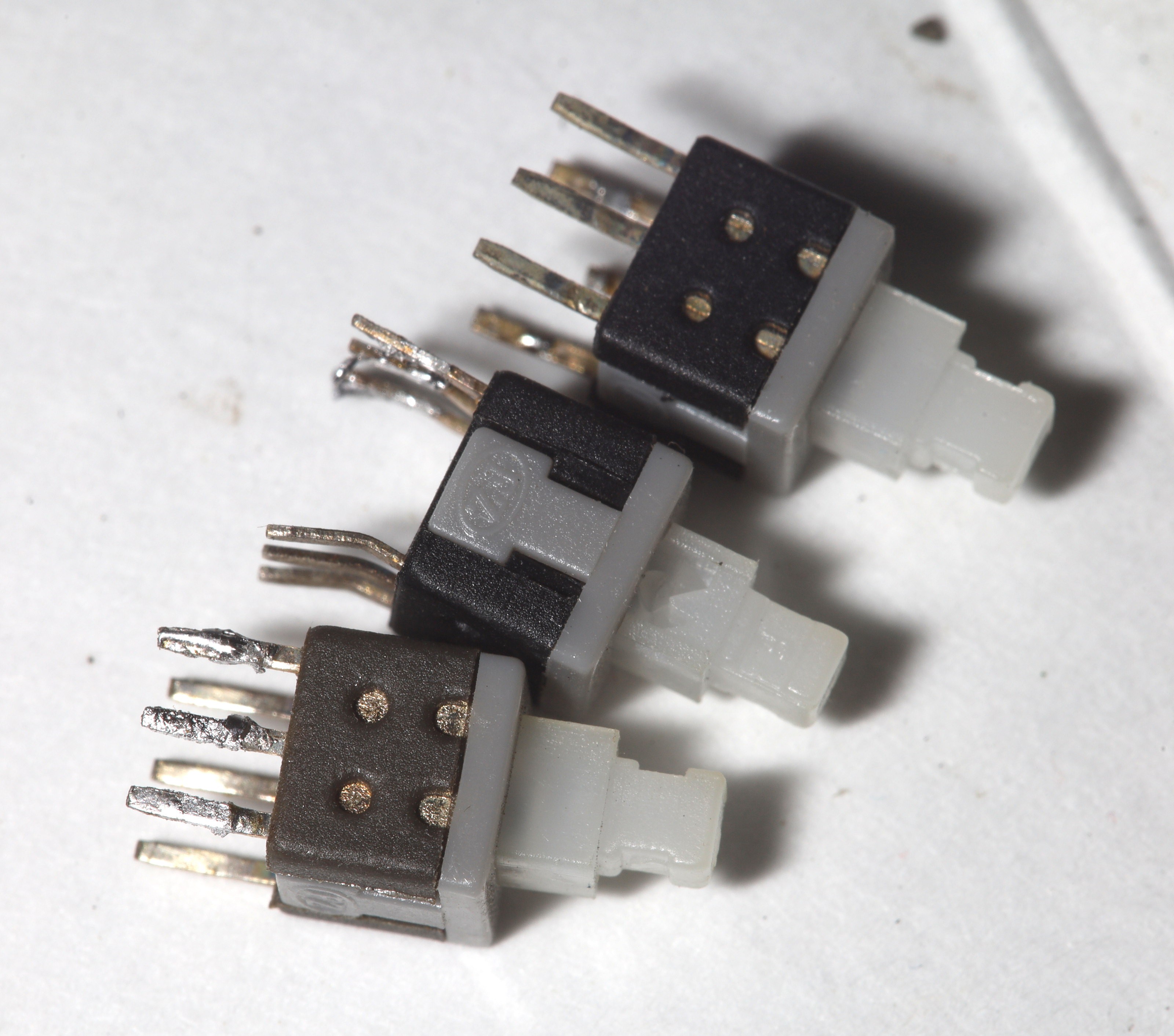
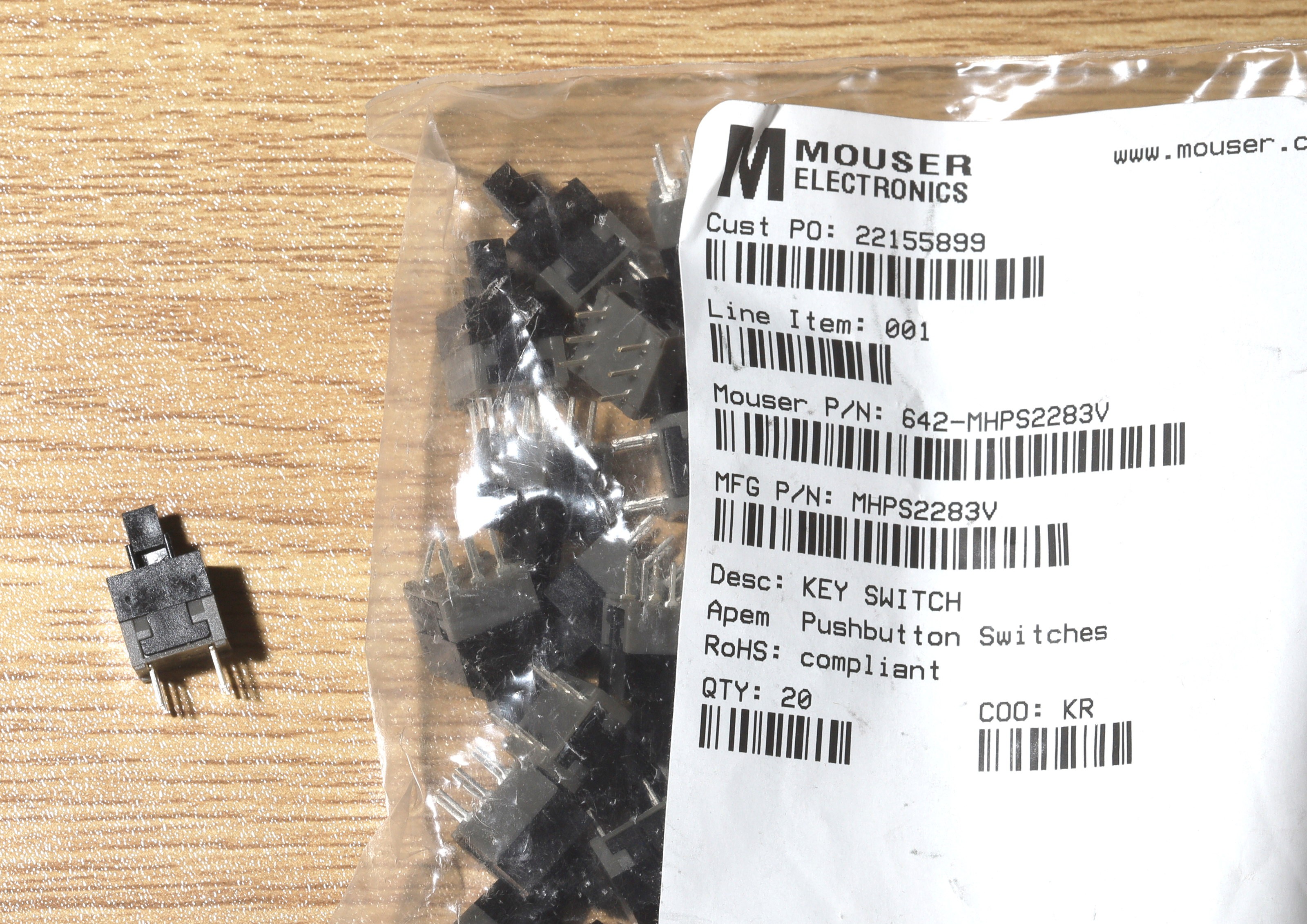
There was some regret after buying the 8.5mm MHPS2283 switches instead of the 6mm MHPS2266 switches. It turned out there were a few 2266 switches in some doll hair LED lights which arrived before the age of 3D printing. They must not have been seen as useful, since no custom enclosure could be printed. Now that they can be used, they're garbage. They're just too small to give the satisfying click of the 8.5mm. They're also a lot more fragile & wouldn't last long. The 8.5mm were what we had in the 80's & they defined satisfying clicks for lions.
There is a need to build new remote controls for a camera, so the choice of switches has arisen again.
-
Death of PLA retaining rings & servos
09/12/2021 at 05:50 • 0 comments![]()
![]()
Sharpied the final designs on. PLA+ is shinier than PLA, making it look slightly more upscale, but PLA+ is expensive so the lion kingdom didn't order any more after the container.
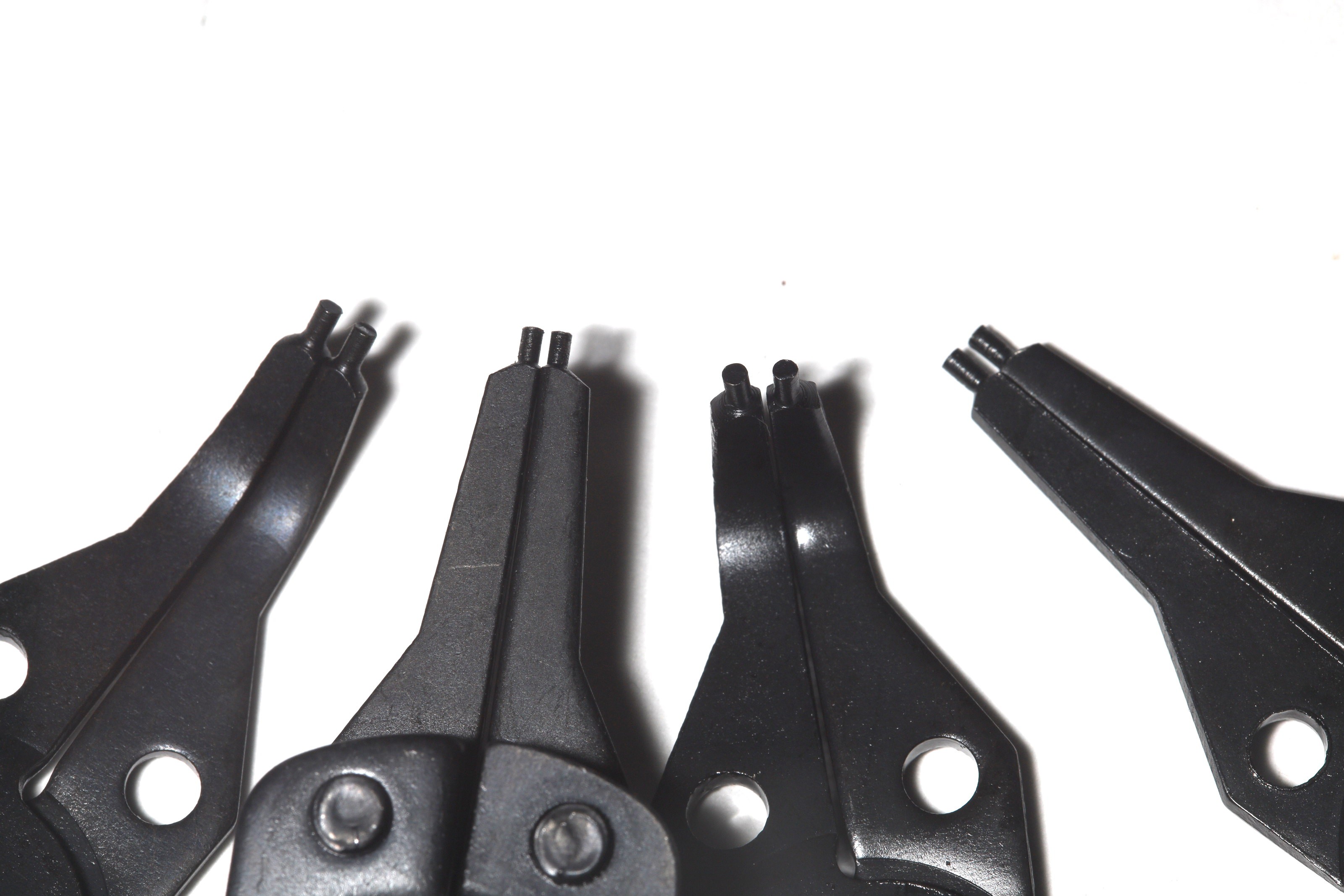
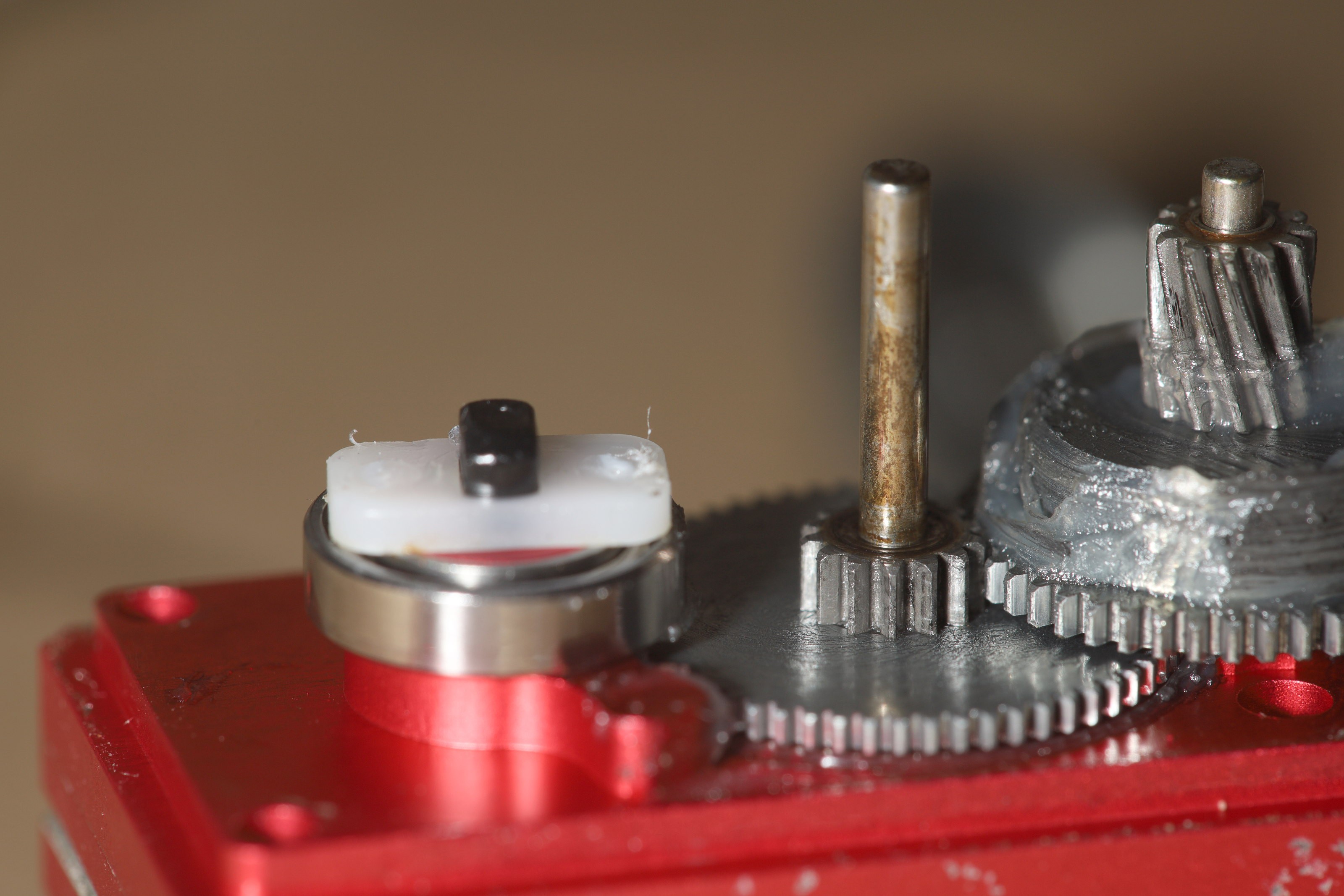
Sadly, the latest retaining ring popped right off. 1 problem is it can't be inserted bed side up, so it has a bevel which just slides off. After a moment of grief & debating destructive shaft modifications, the decision was made to spend $25 on a set of steel retaining rings & a retaining ring tool. It was as much as a new motor.![]()
![]()
![]()
![]()
![]()
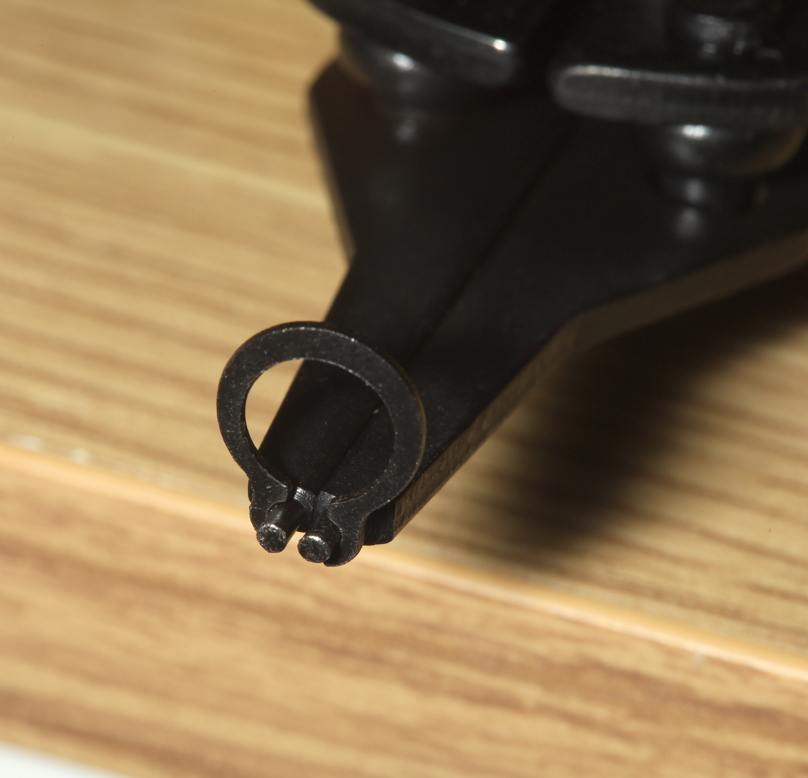
This tool doesn't fit anything smaller than M6. M6 requires the aid of a metal rod to separate the ring.
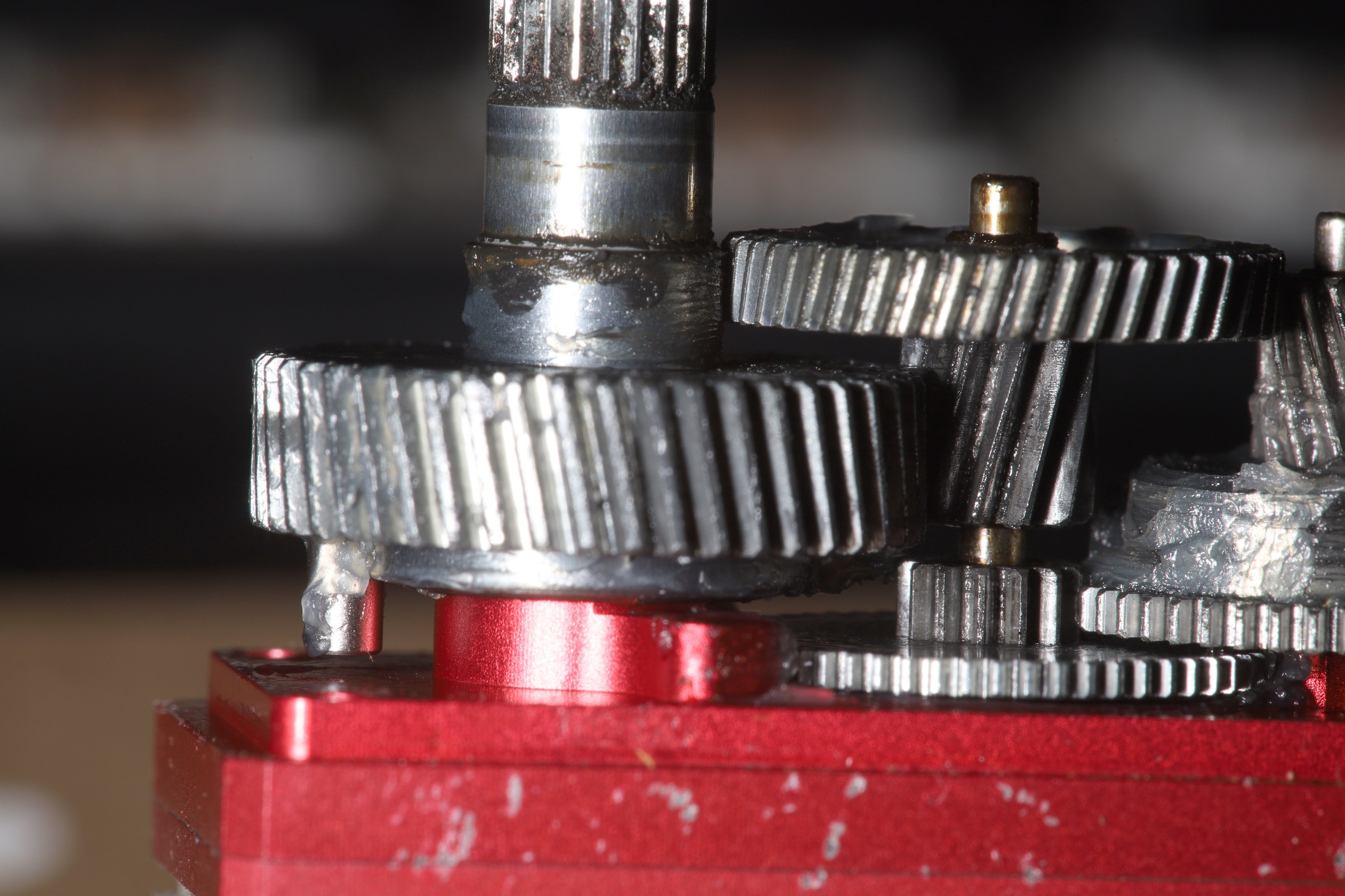
The era of 3D printed retaining rings had come to a close, after 6 months. The problem with modifying the shaft for another PLA structure was how a more robust PLA retaining ring would slide on. It would entail removing the encoder & then removing the pin, instead of just removing the encoder. Getting the right tool for the job was the only way.
![]()
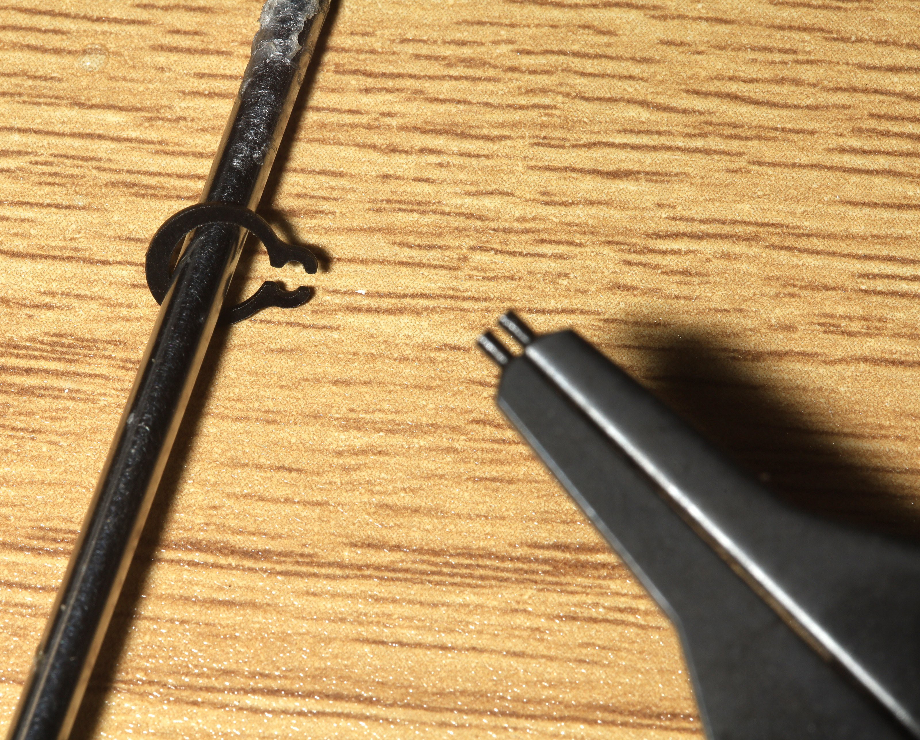
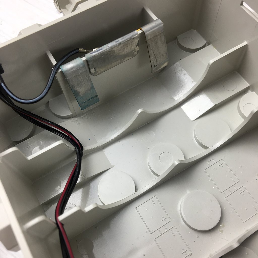
Stashed a repair kit in the battery compartment while waiting for the snail mail shipment of retaining rings. This can unbolt a wheel & either reseat or remove an o-ring. Lions haven't had any luck reseating an o-ring in the field, but a sharp screwdriver can cut through TPU. The battery compartment has enough room for contraband, but if screwdrivers aren't pointing forward, they'll get trapped.
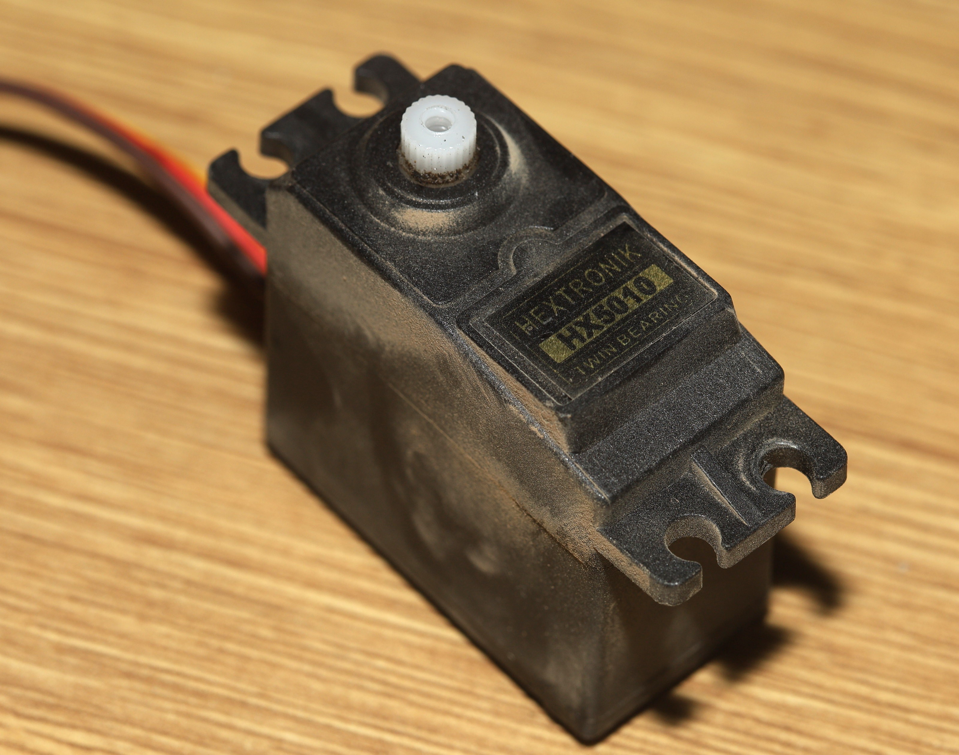
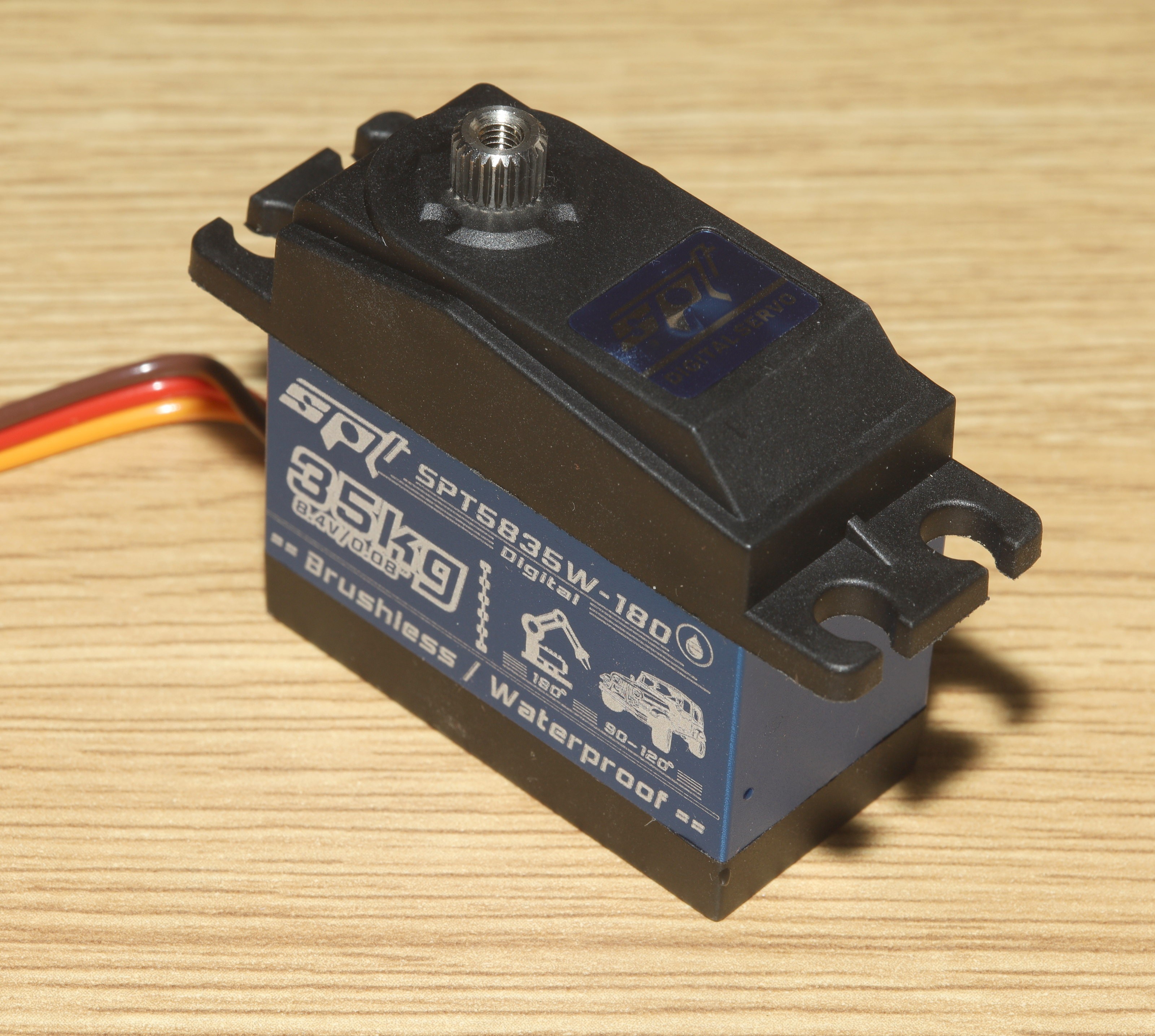
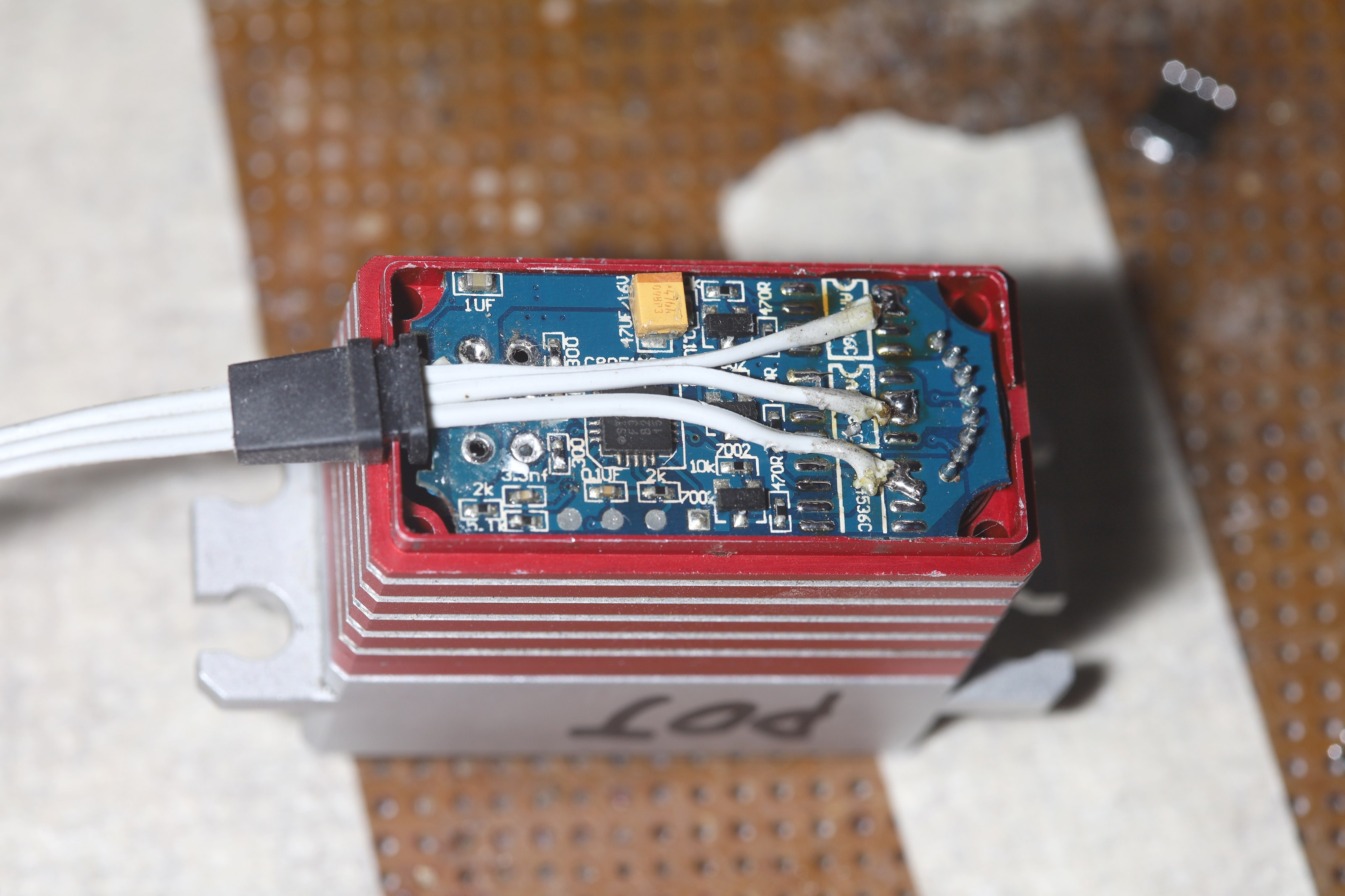
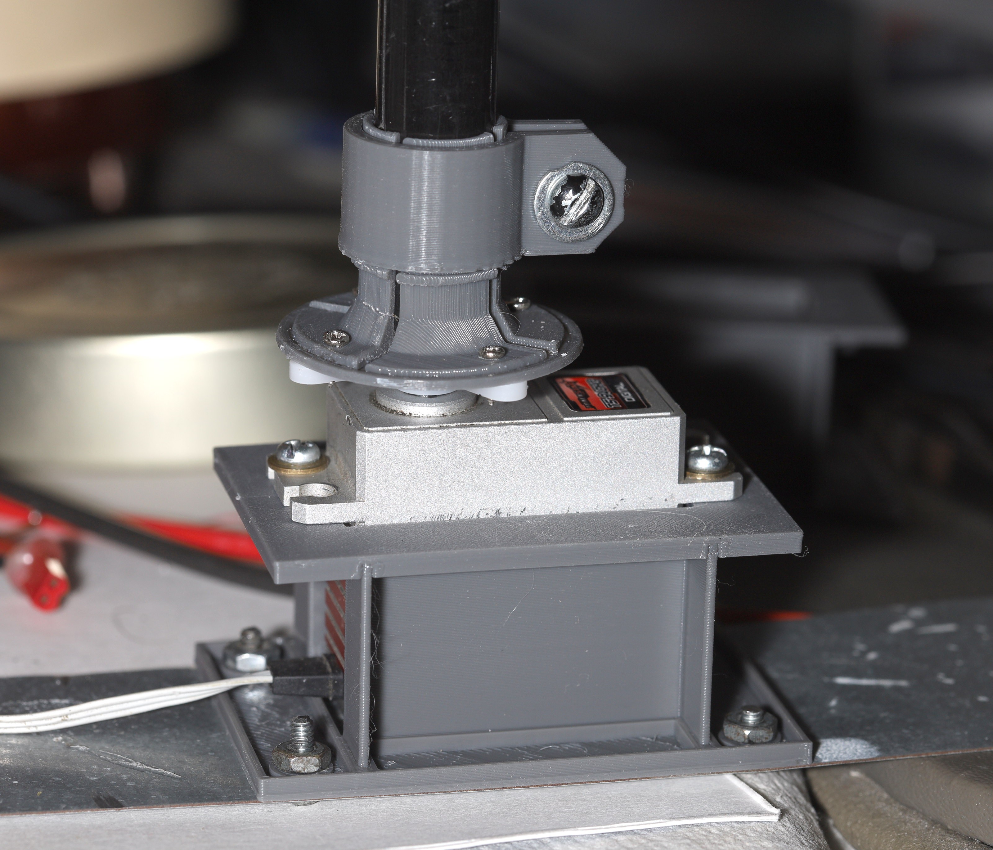
In servo land, the SPT died the same way the Hextronix died, a sudden full left lockup followed by intermittent restoration after wiggling the cable. Power cycling it did nothing. It's been 7 years of chasing erratic servo behavior. Most of it might be pots & motors wearing out. The last few have been converging on the wiring.
The cable has been already replaced. Replaced it again. This one is coming down to a loose solder ball or dry solder joint. So that's 2 days of not going anywhere because of a retaining ring, dead servo, dead 3D printer.
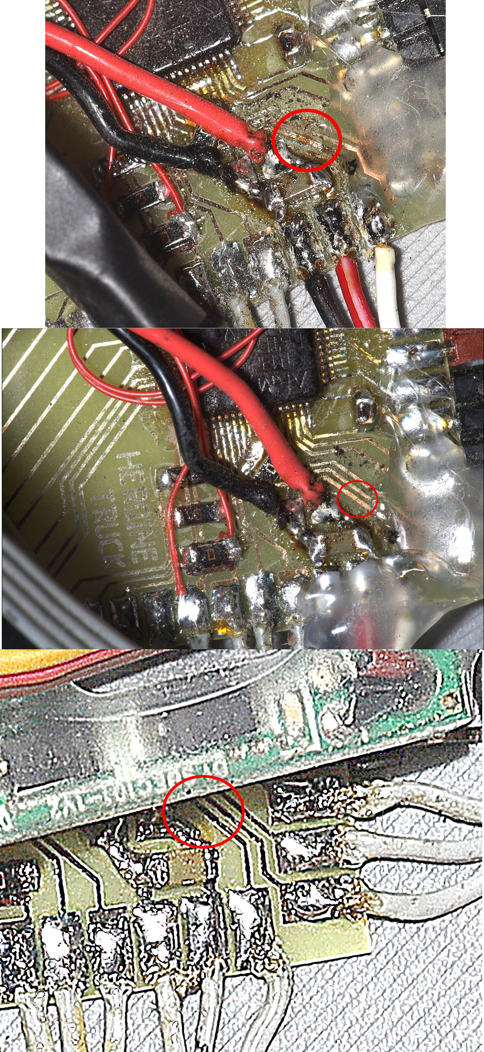
Pressing down on the board in just the right way got the servo to glitch reproducibly. Only after thoroughly cleaning the PWM trace, the problem finally appeared.
![]()
There was a micrometer scale break in the trace, completely invisible when it was dirty. It's believed to have been there since the board was made. The board was made with a dedicated buck converter for the servo. An xacto nicked it while cutting a wire to the buck converter. The oldest photo is too small & dark, but some grotesque unsharping reveals 3 slightly brighter pixels in a row where the break was spotted later.
The break only cost $35 in unnecessary new servos. The previous $150 of servos were bought during the lunchbox days to solve common wear.
![]()
There was another bought of overheating motor. It was blamed on a tangled cable jamming the encoder, but there's no obvious way for it to get in the encoder. The cable was pulled tight, since untangling it would be a full day. Another idea is current in the cable interferes with the hall effect sensors.
![]()
![]()
![]()
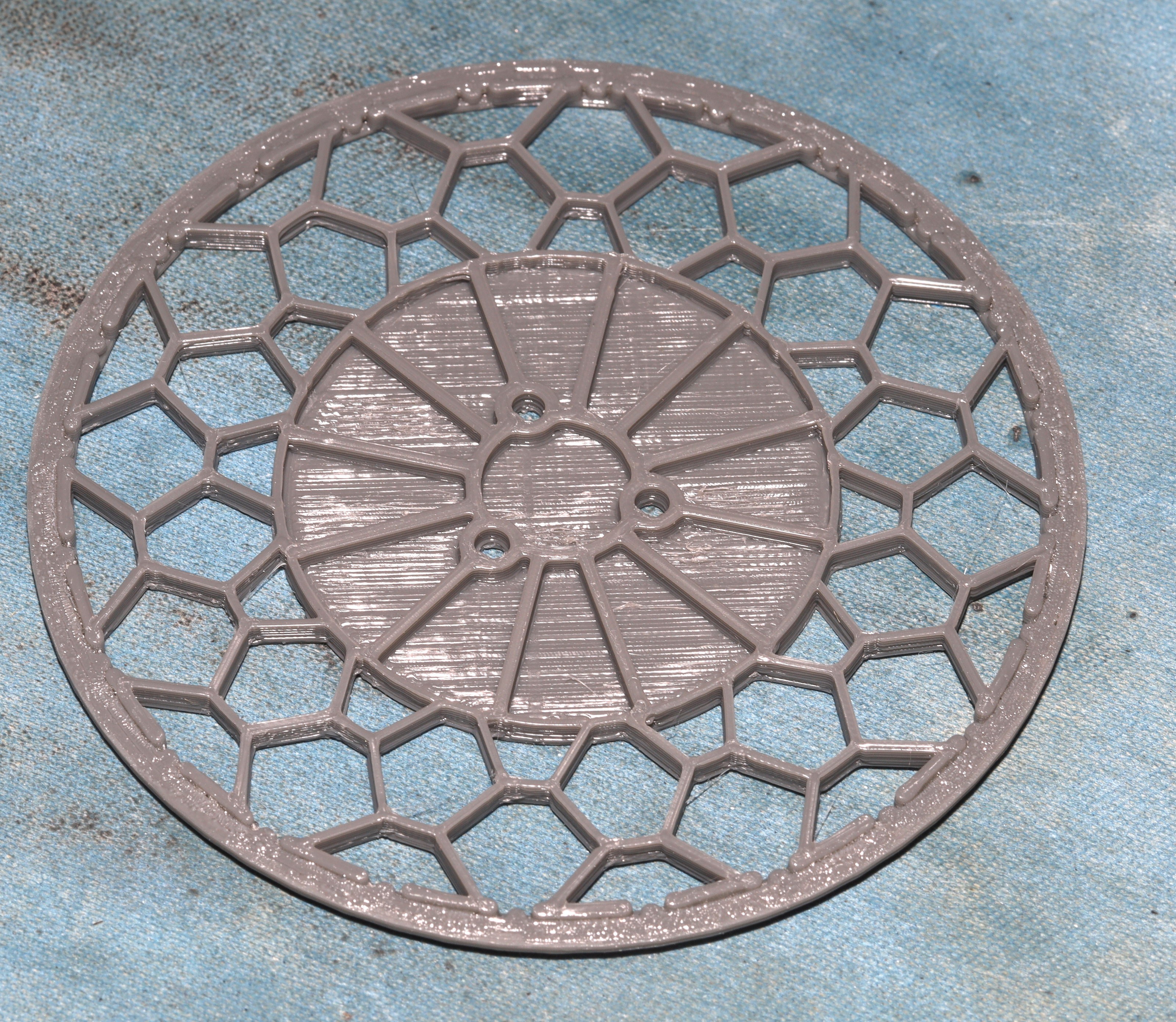
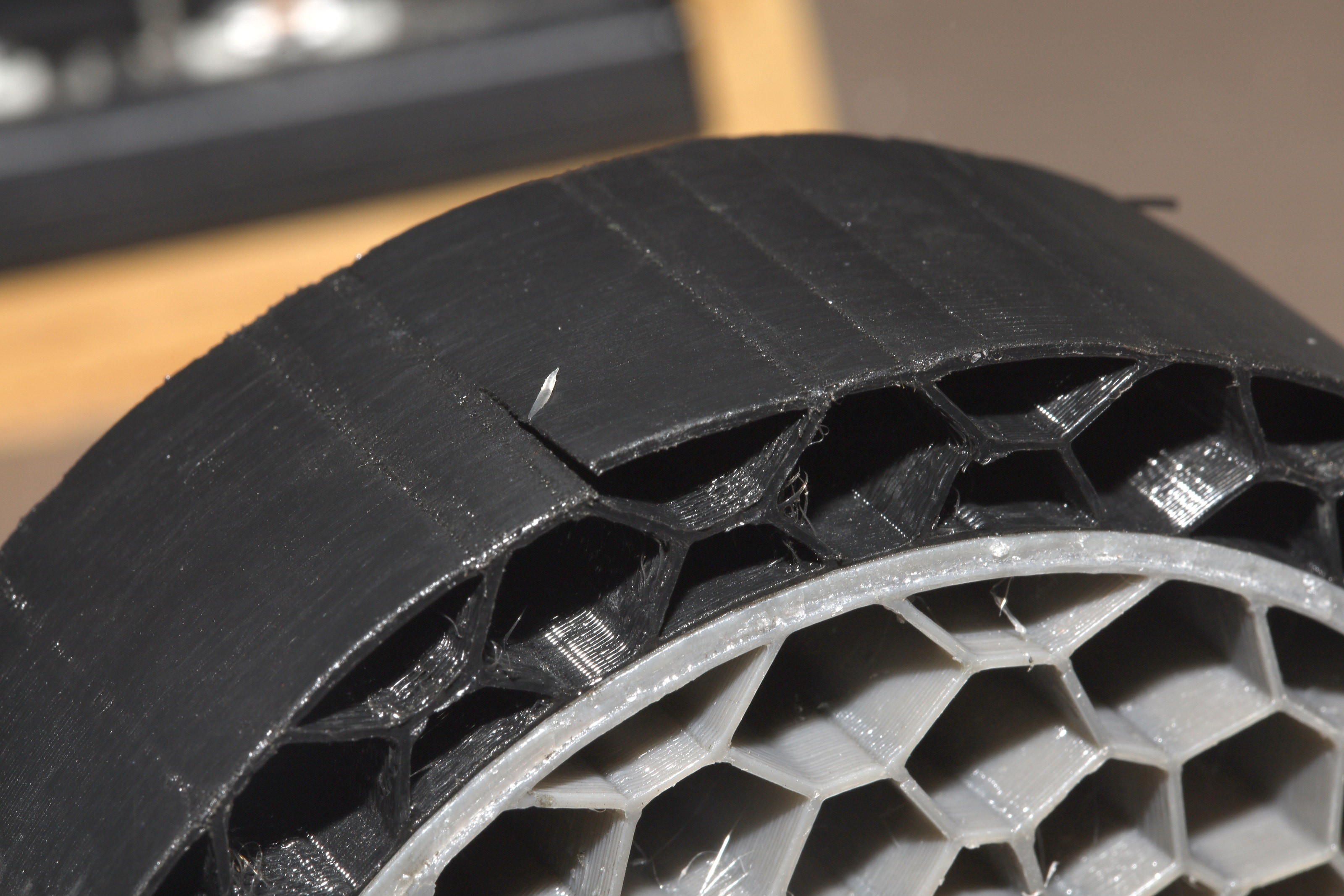
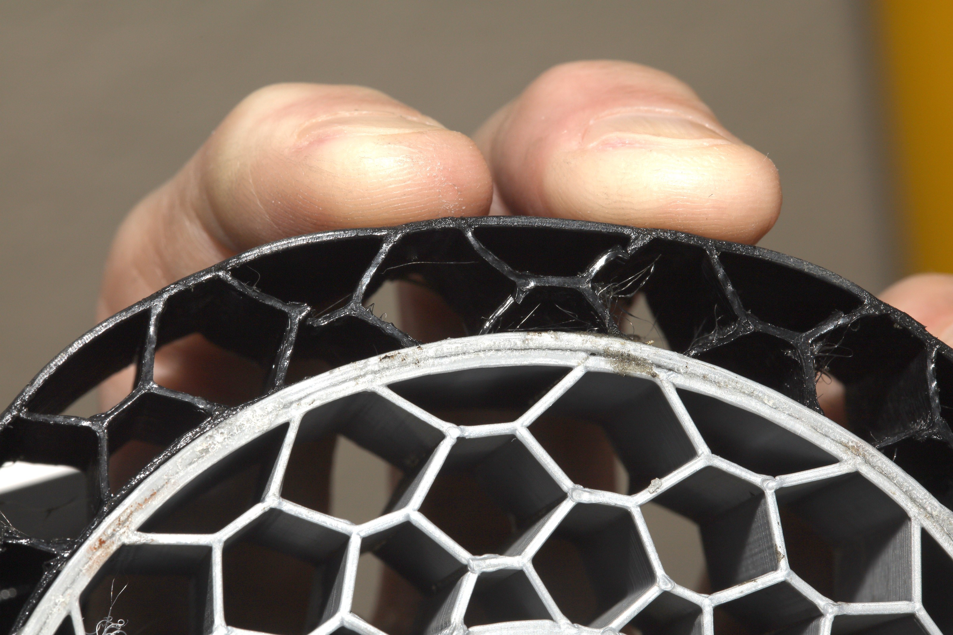
Finally, there was a case of a tire appearing normal, but actually coming out softer than a sponge. The filament became hydrated from a swamp cooler. It was cosmetically indistinguishable from a normal tire until analyzed under a microscope. Something must be done to more reliably dry TPU.
This brings us to the motor module. The use of self tappers as load bearing farsteners is a disaster of biblical proportions. The latest thinking is to use captive 4-40 locknuts & hot glue to farsten the locknuts. The motor module might have to be printed with a .4mm nozzle.
-
Container #3
09/09/2021 at 21:02 • 0 comments![]()
![]()
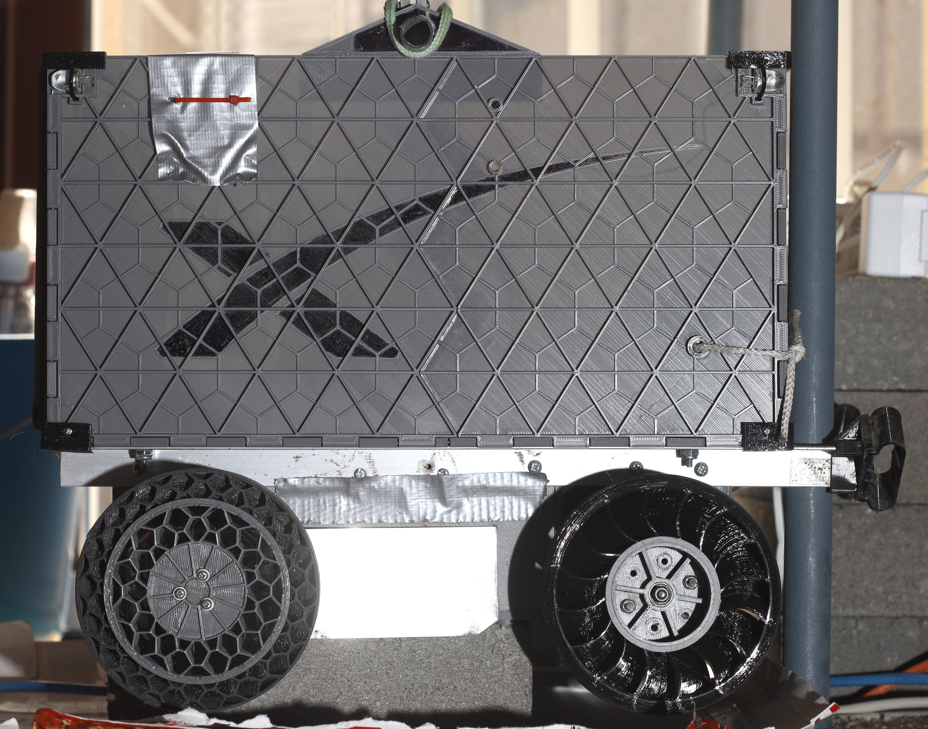
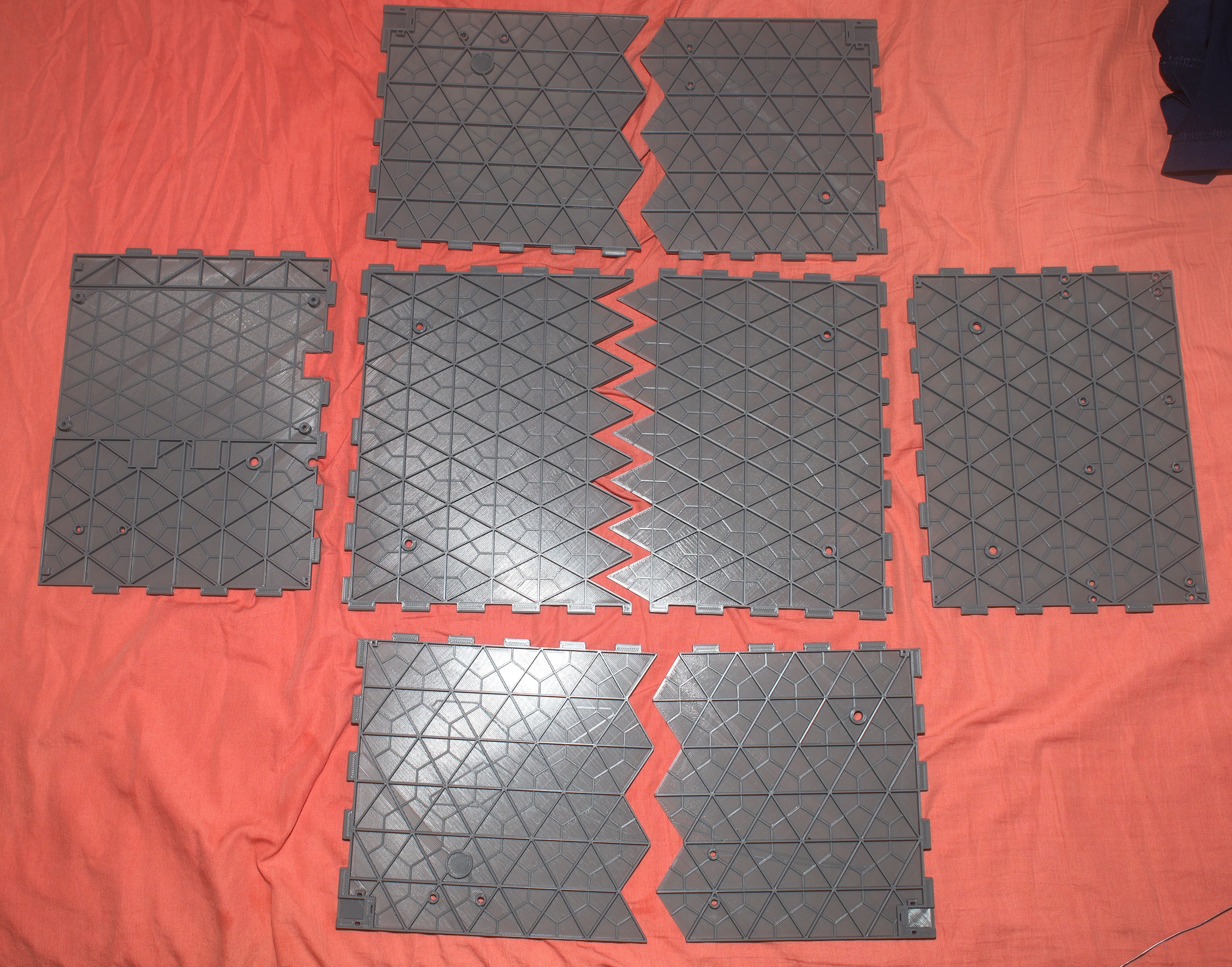
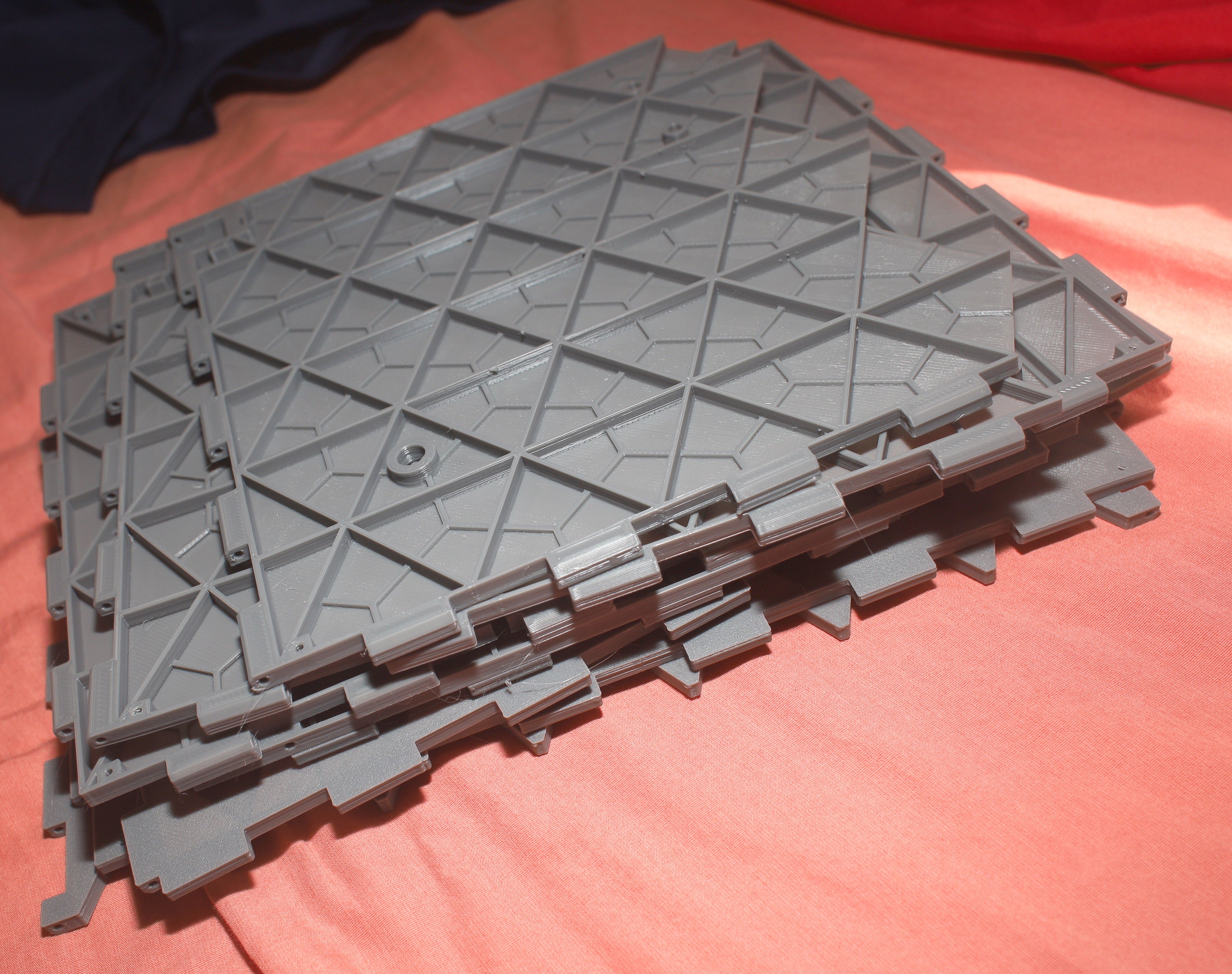
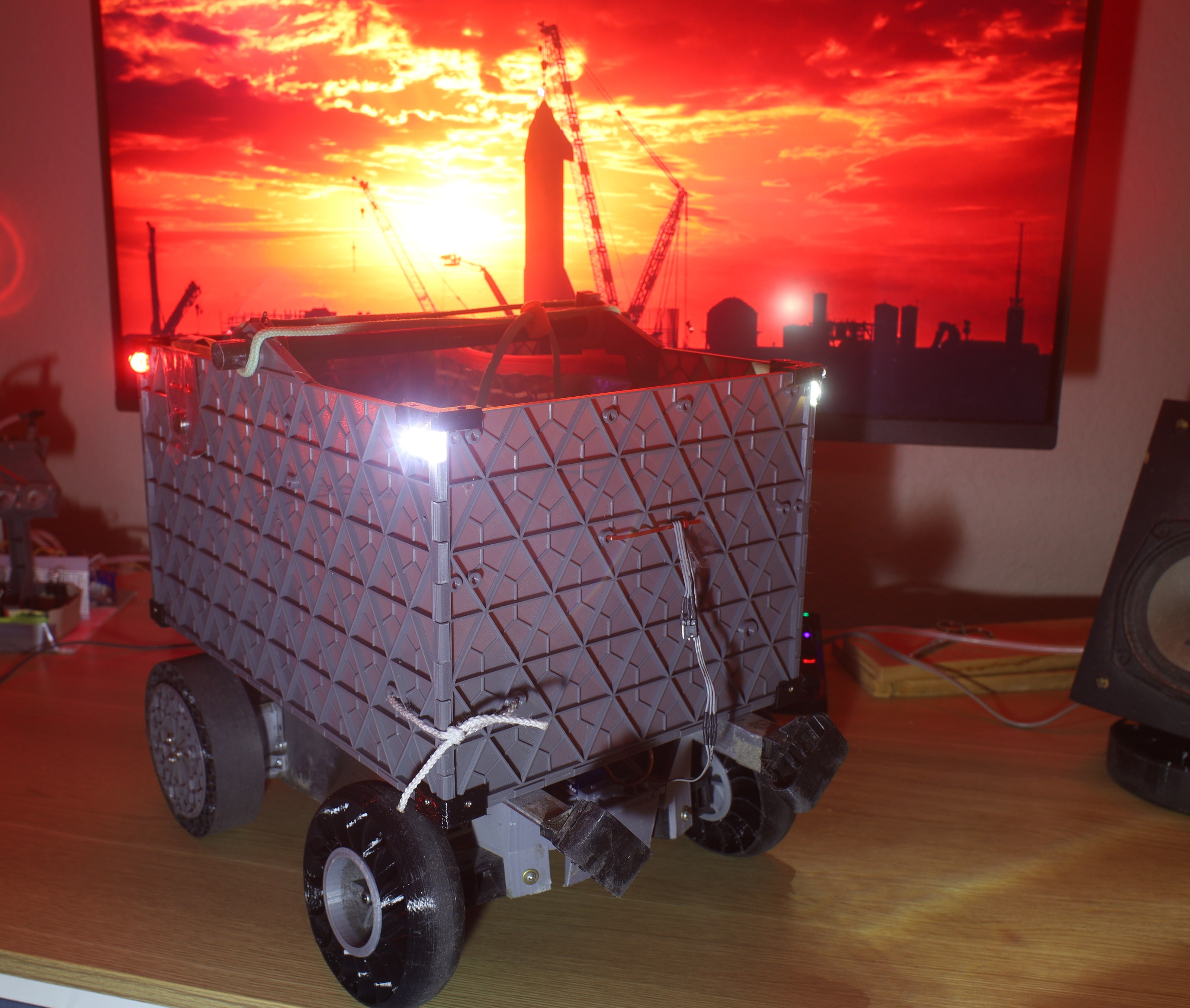
After several days, all the panels were done filament depositioning. None of the 228mm ones had any showstopper defects, though they improved over time. The last panel was a narrower one with no bed heating, but the 228mm ones definitely required it.
![]()
![]()
![]()
![]()
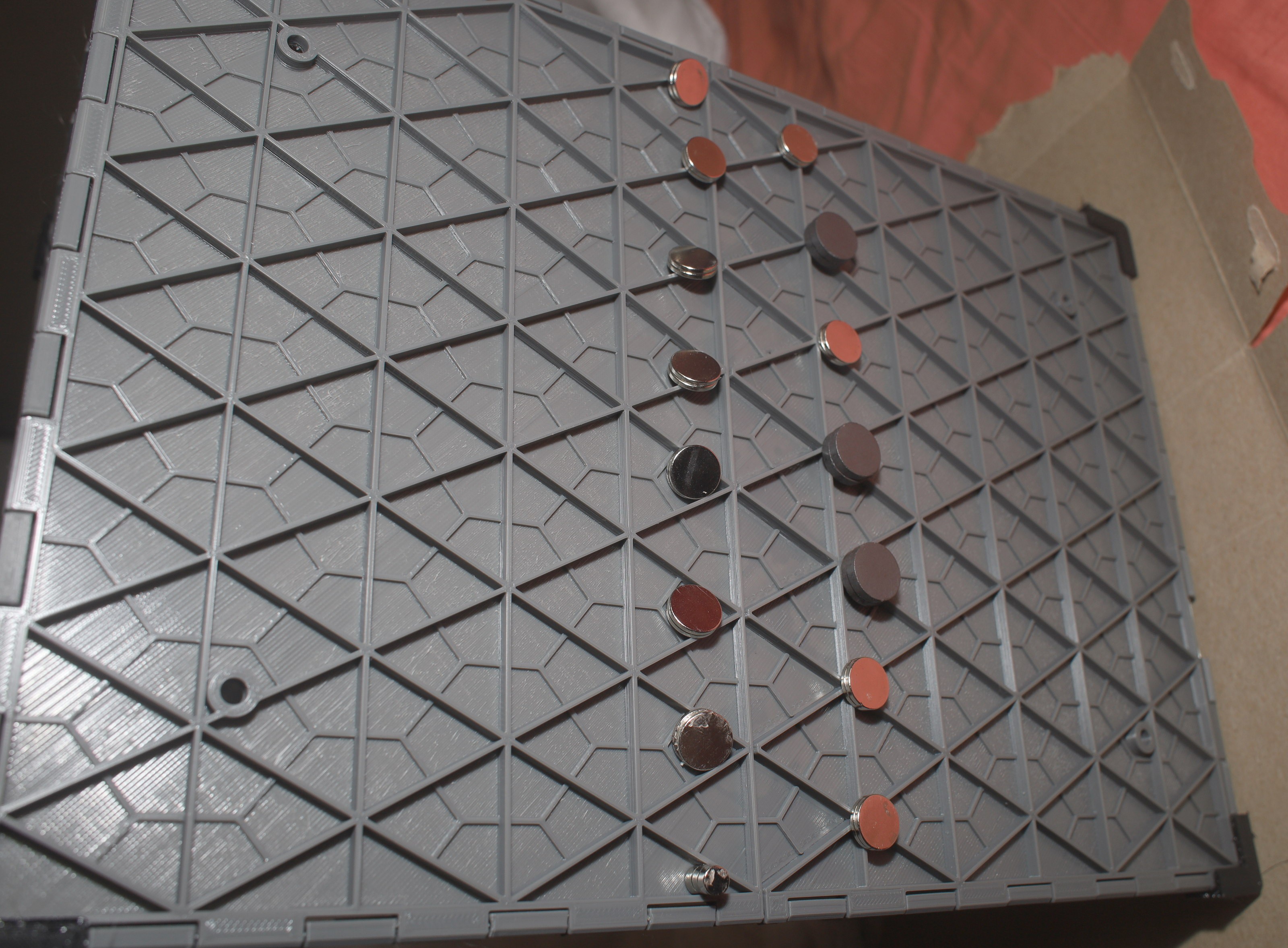
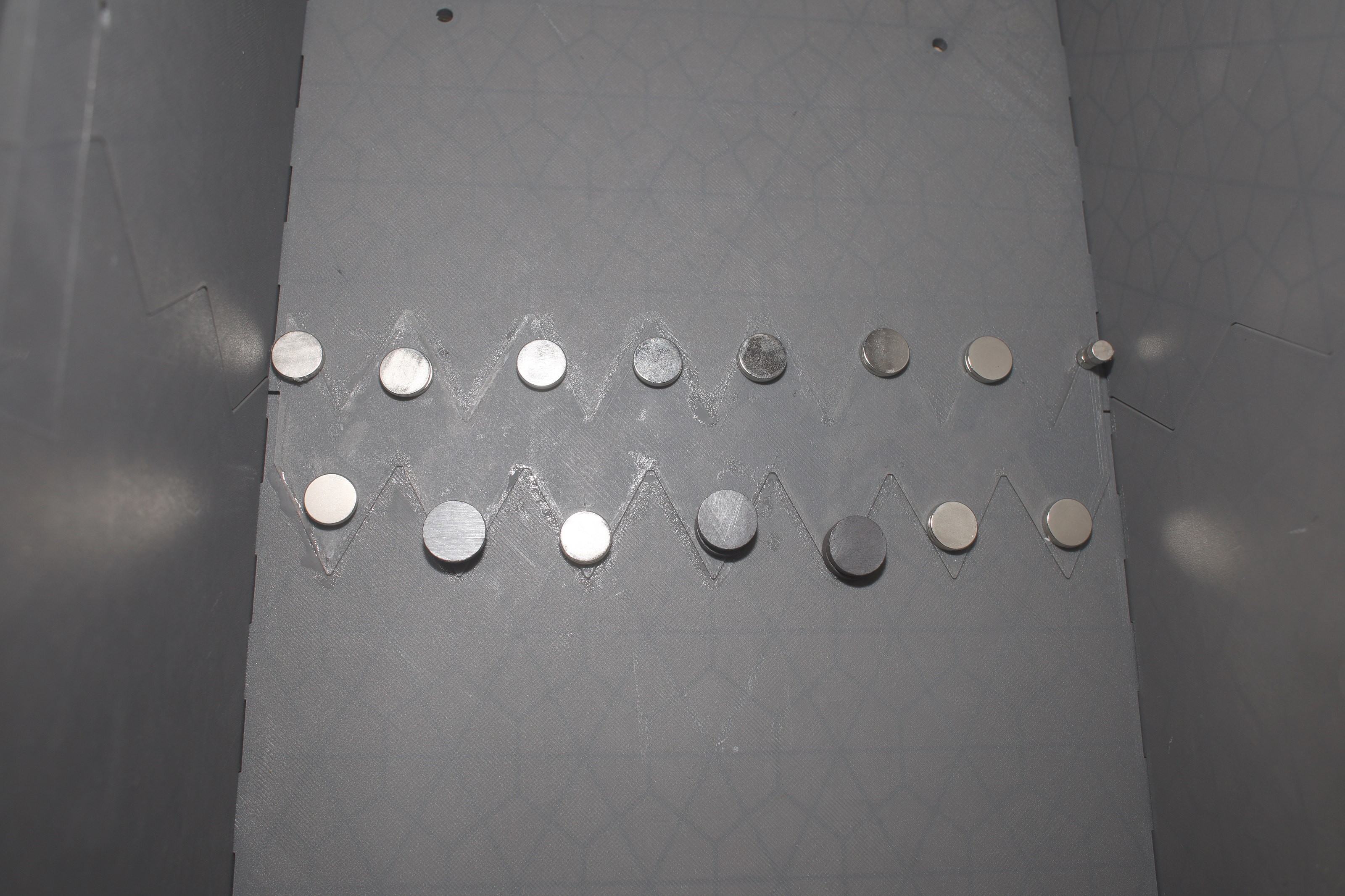
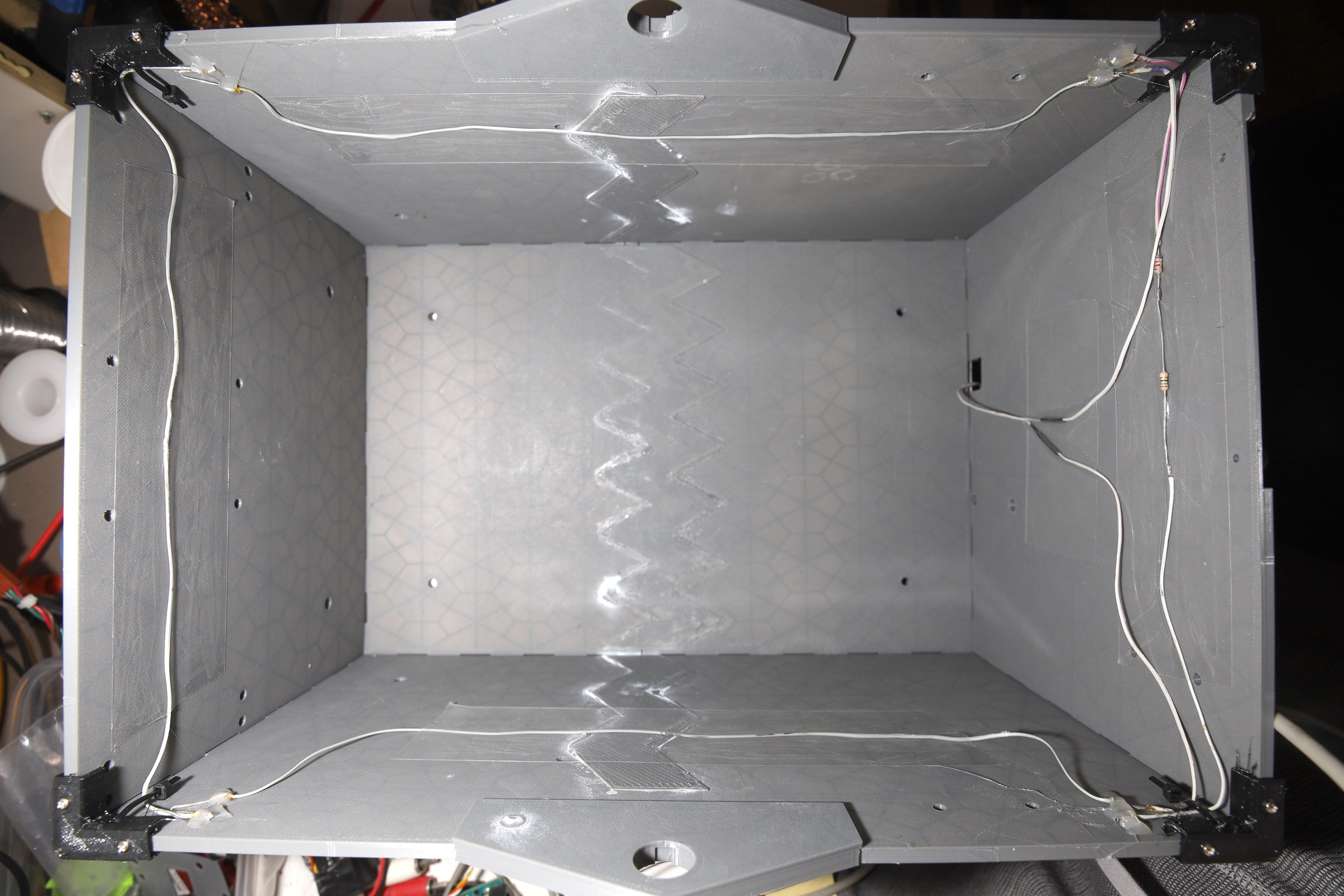
There was an attempt to evolve joining the segments to use PLA zigzags. This was the 1st attempt at expensive printed tape. The mane problem was clamping it to get the adhesive to stick. Magnets were terrible. It really needs a big, expensive jig. 1 piece goes on the flat side. The other piece needs pins pressing on all the facets of the other side. The final solution was spraying water to accelerate the glue, but water leaves a white film.
![]()
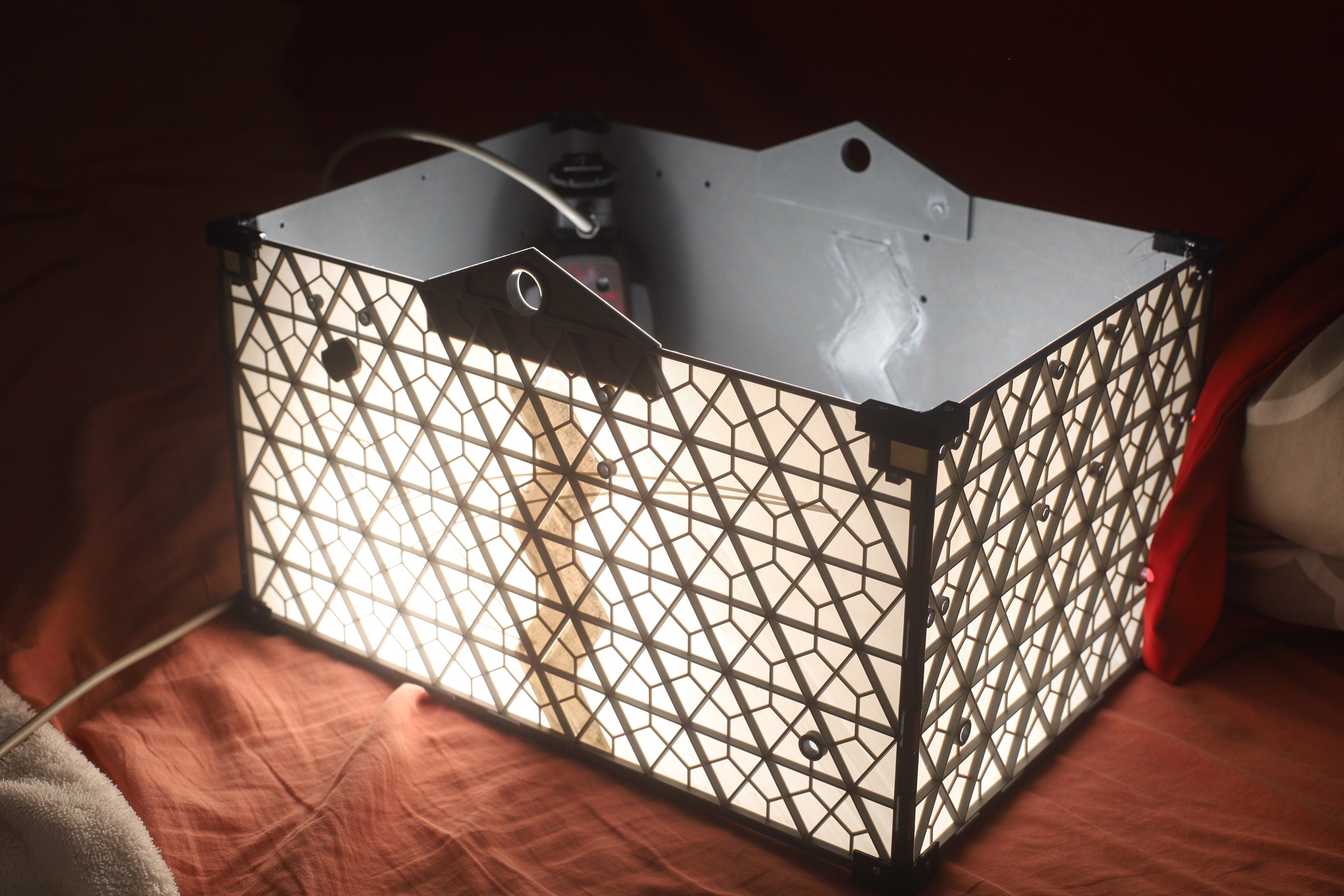
Despite the artifacts, the hassle, & the price tag, the zigzags were visually lightyears ahead of duct tape. The mane issue is how they look when light shines through the panels.
![]()
![]()
![]()
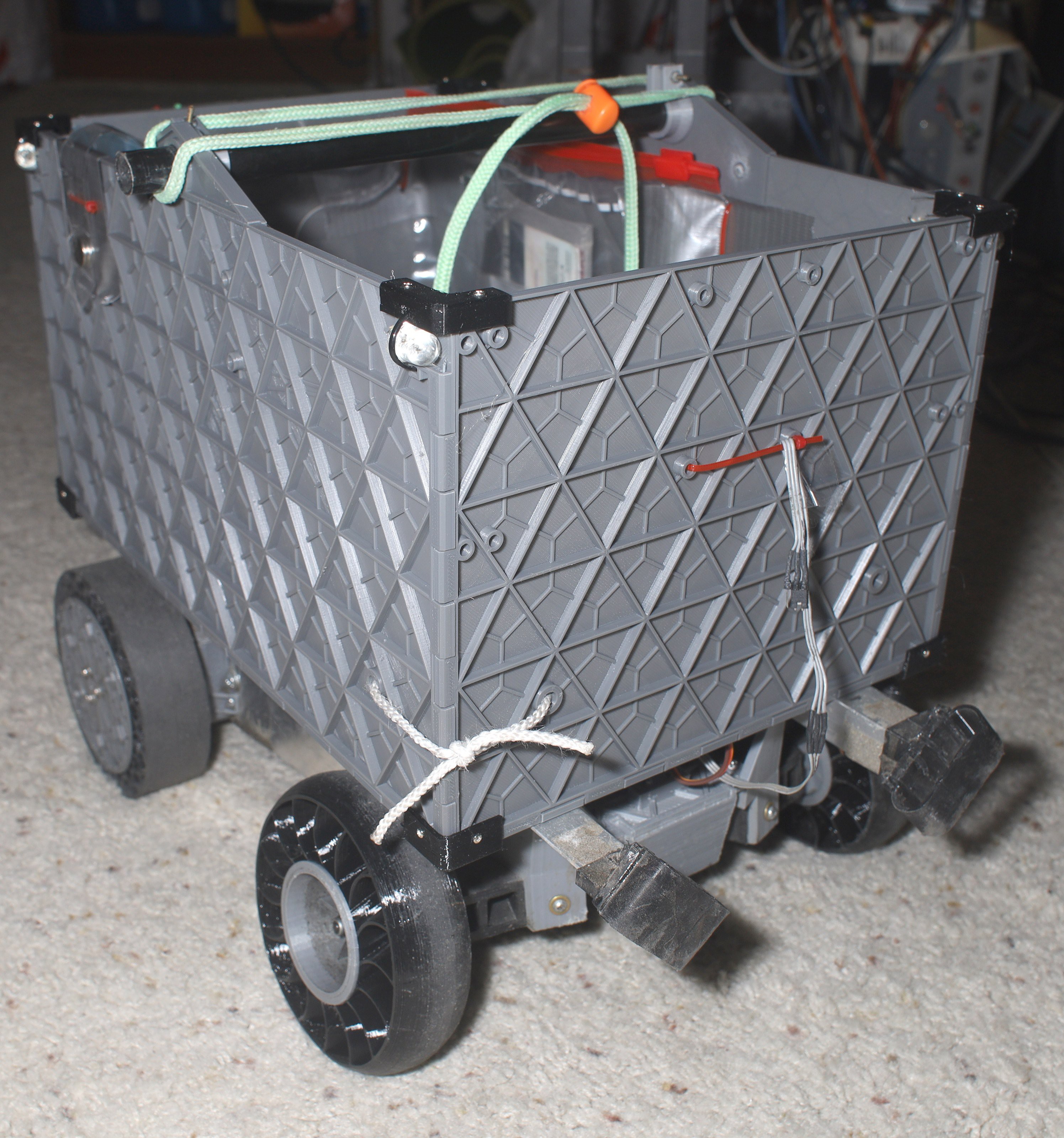
The corner bumpers had a lot of delamination. They definitely needed 2mm walls & .32mm layers, but the TPU absorbed a lot of water from the lion kingdom's air conditioning.
![]()
![]()
![]()
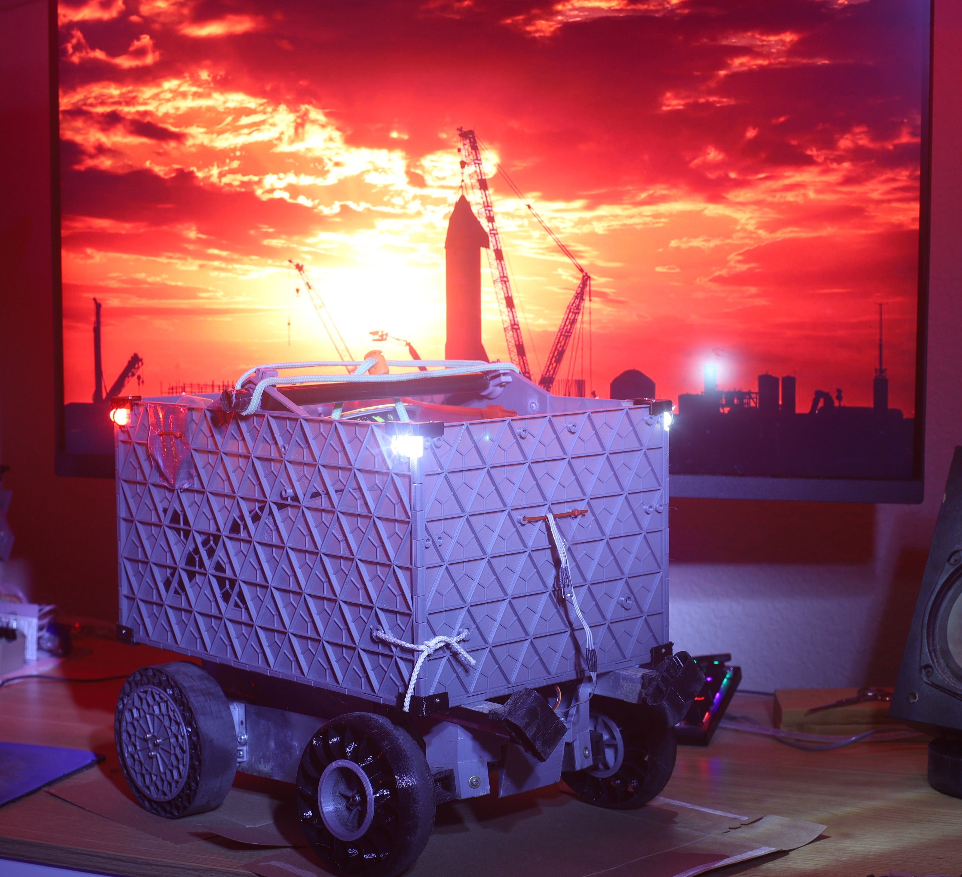
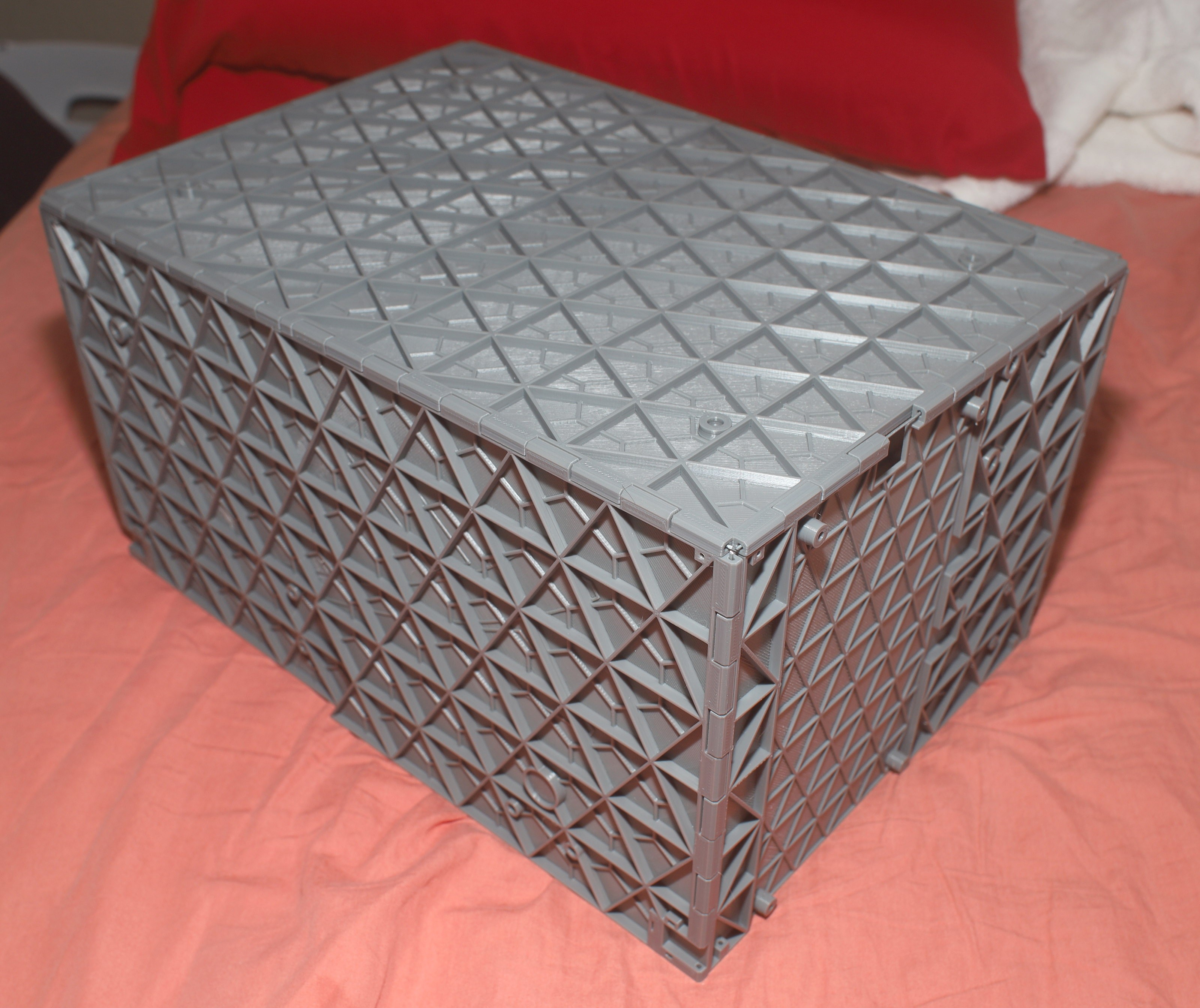
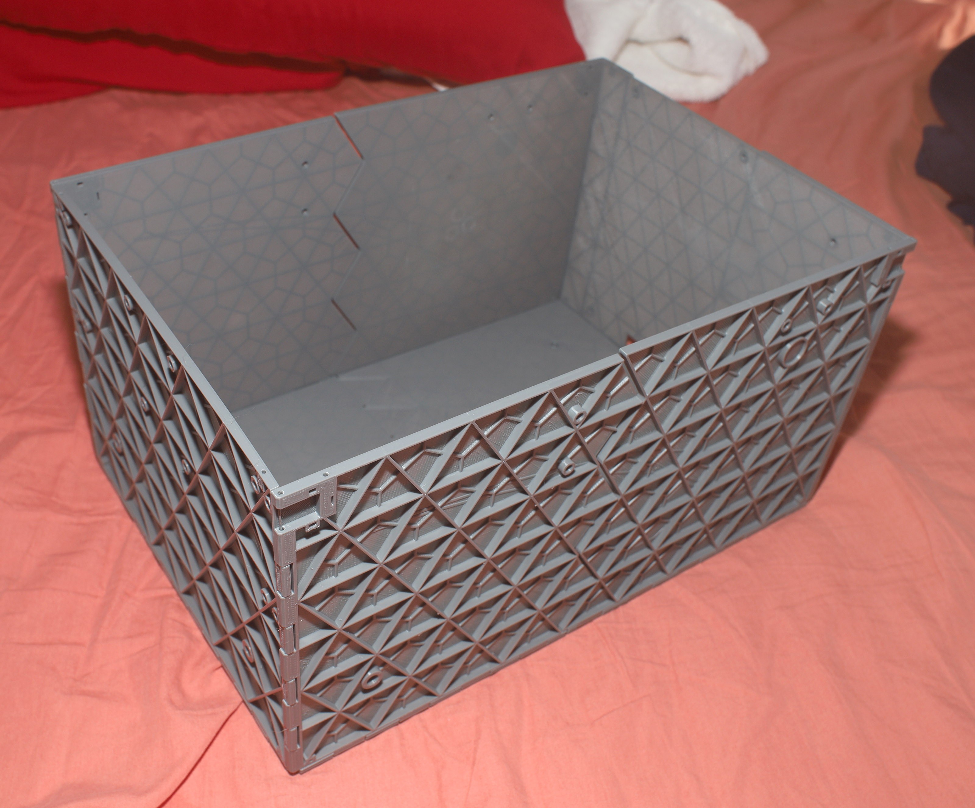
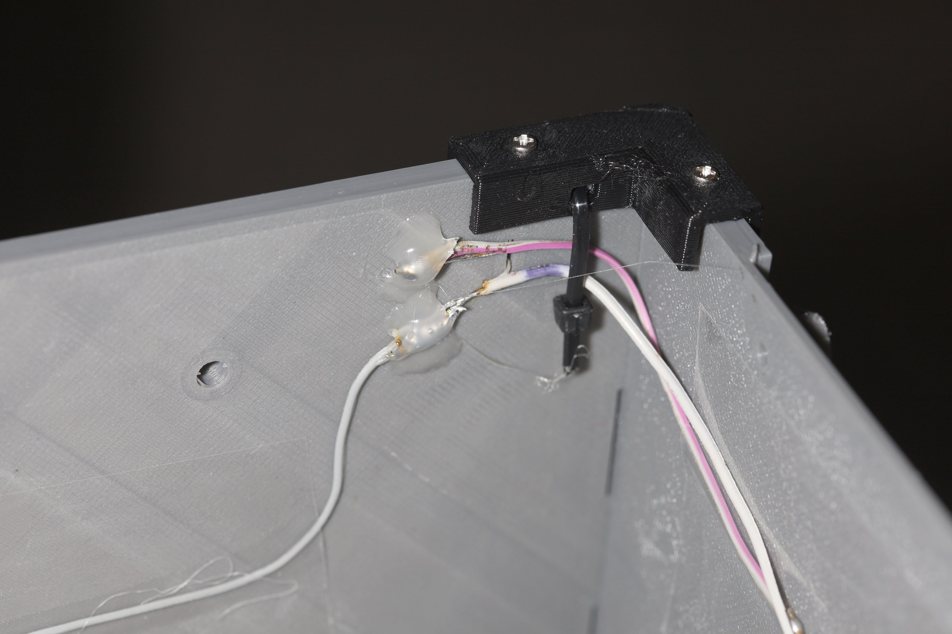
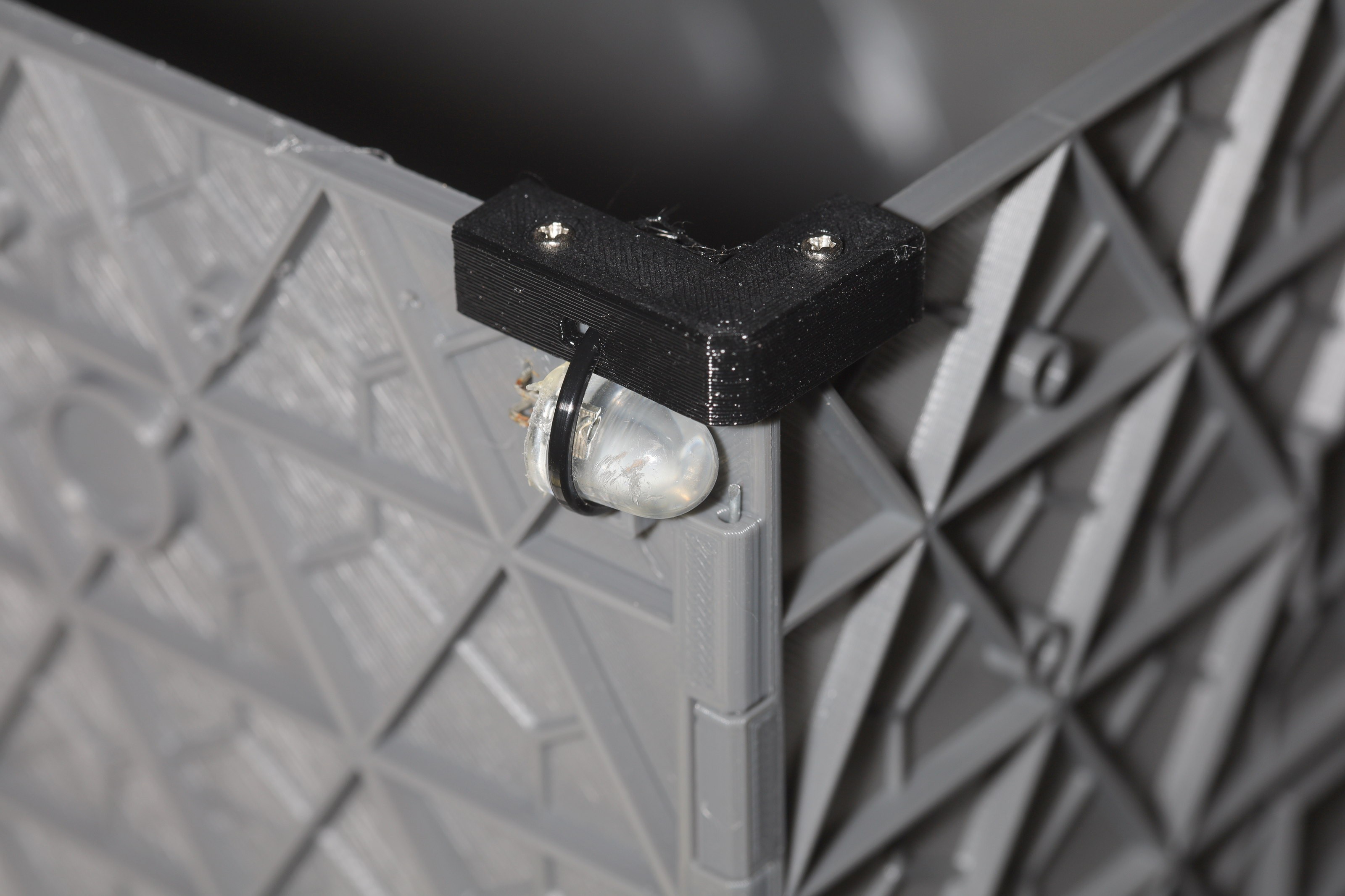
Lighting used a slightly improved hot glue process & no solid core wire after all the solid core wire broke in the last container. The 3D printed containers have a lot more flexing near the corners than coroplastic.
![]()
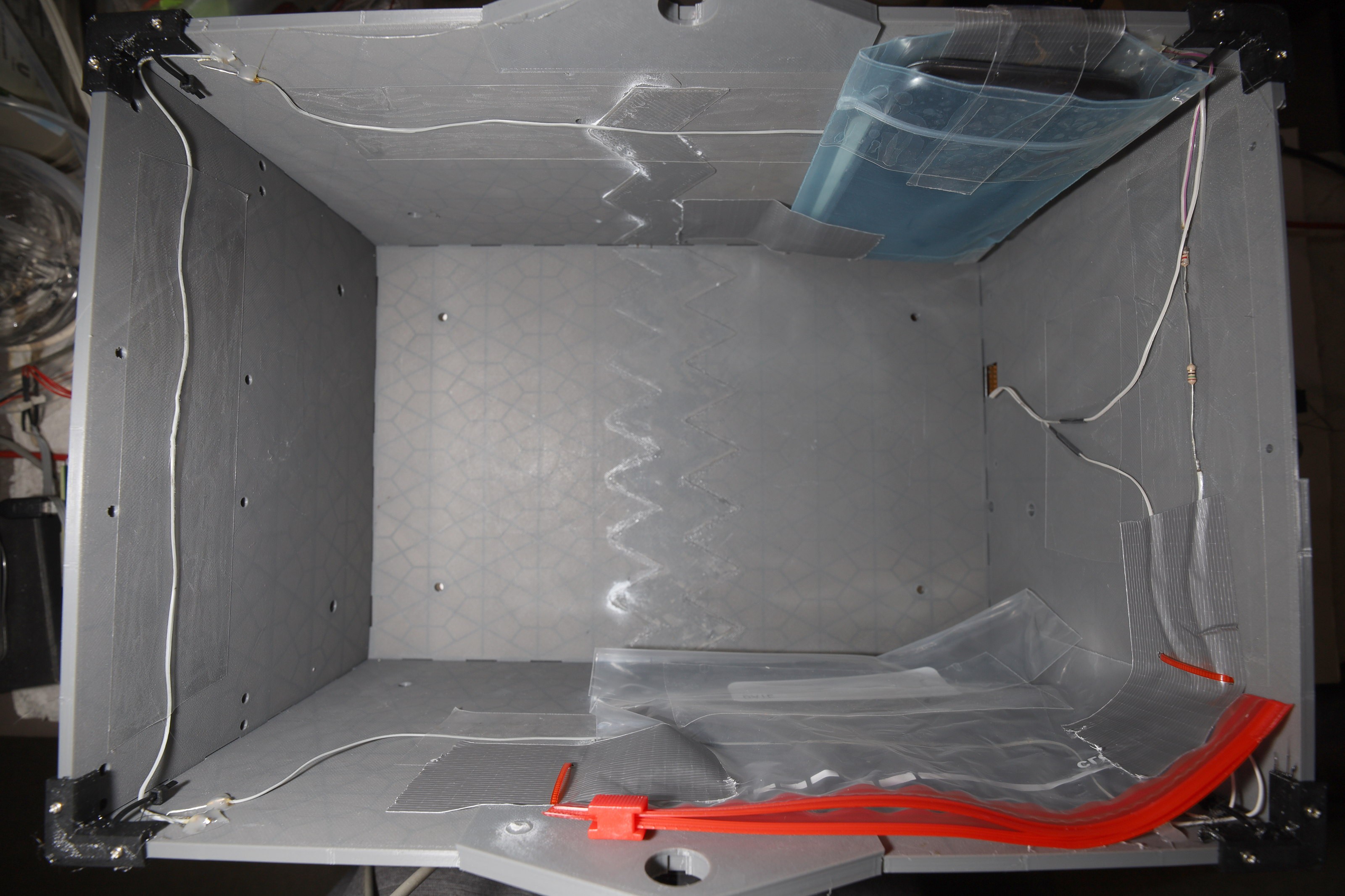
The standard storage compartments went in with duct tape since duck with zip ties has been very robust.
![]()
![]()
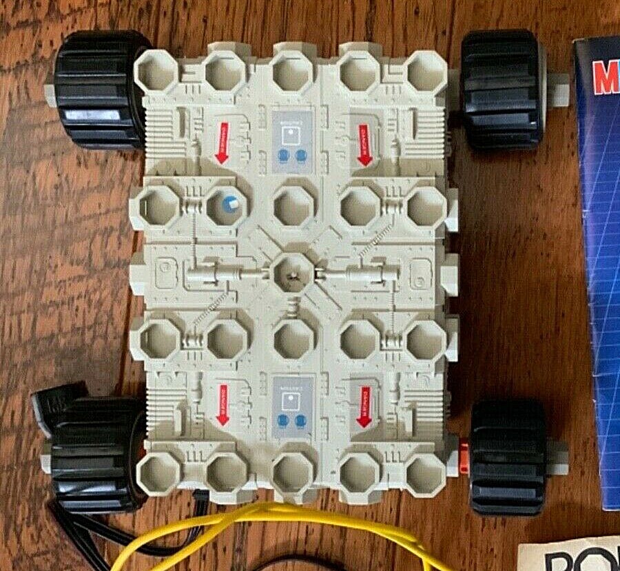
The lion kingdom likened its own container design to the battery box in the Robotix R-2000.
![]()
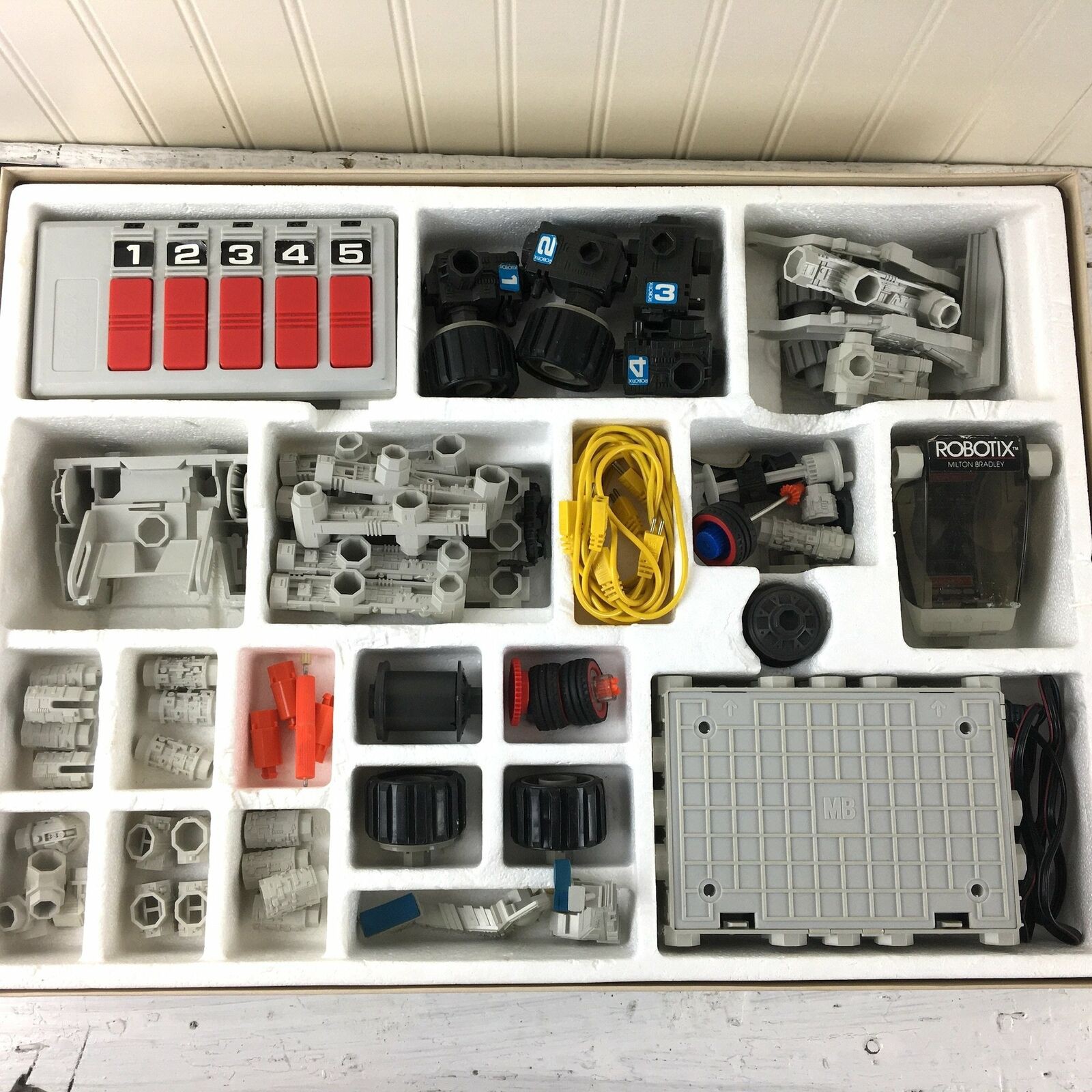
According to random ebay photos, the top had a lot of artwork, but it also had a lot of functional polygons for attaching bricks.
![]()
The bottom was a simple grid for strength. There was no effort where plastic needed to resist the downward force of D cells. The cleverest part of that kit was a switch for a 5th servo, but only providing 4 servos. A kid would pay a fortune to get a 5th servo. Those were very high torque, 360' servos.
Apparently, the battery bank was center tapped to provide reverse voltage to the servos. Semiconductor H-bridges were a fortune in those days, so the answer was 3 rails. The lion cub had no concept of cost savings & just thought the 3rd conductor was a professional touch. Honors & benefits already at the age of 9.
Today, paying an animal to solder a center tapped battery terminal would cost a fortune compared to using H bridges.
![]()
The inside had some placeholders for the batteries, but nothing structural. It just relied on a thick shell, probably a generous 2mm.
The kit in general had a lot of plastic artwork with structural elements, much like what the lion kingdom tried to do. There's a lot of engineering in making sure plastic bits fit together & don't break, before they ever get to the artwork.
Stuff like the Robotix kit was probably designed by Milton Bradley employees in New York city, as depicted in Big. Milton Bradley was a real guy who worked as a draftsman (human CAD program) before trying to sell prints of Abraham Lincoln. When Lincoln grew a beard, his prints became worthless. That forced him to sell board games. Today, the toy companies are all owned by Hasbro & the creative process is all done in China. Hasbro is just a law firm.
-
New servo & helical front tire
09/06/2021 at 21:07 • 0 commentsAnother 400 miles ended with a shredded tire, burned out servo & cracked rod end.
![]()
So the Hextronix died after 394 miles. It was a motor burnout.
![]()
In went the SPT.
![]()
![]()
The front tires came up thrashed from old age & going offroad.
![]()
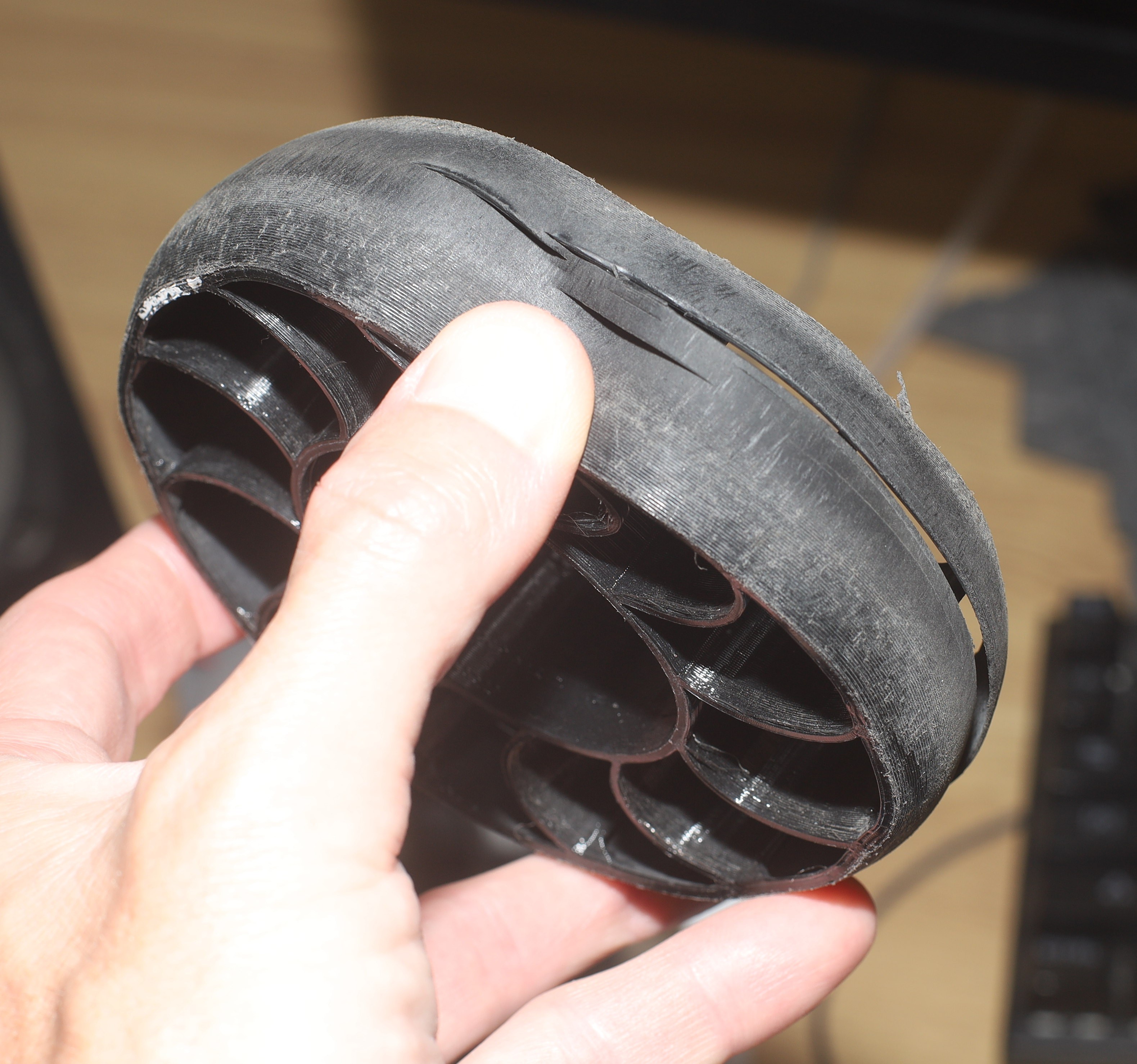
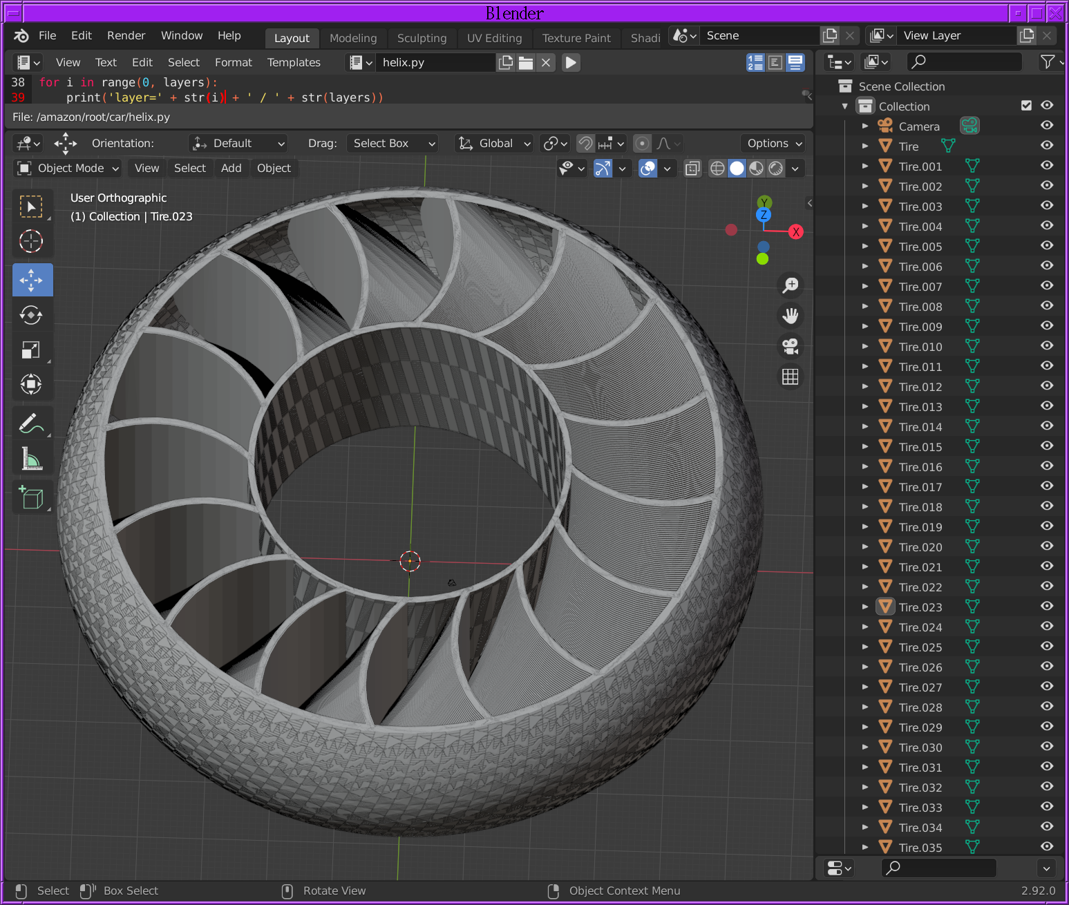
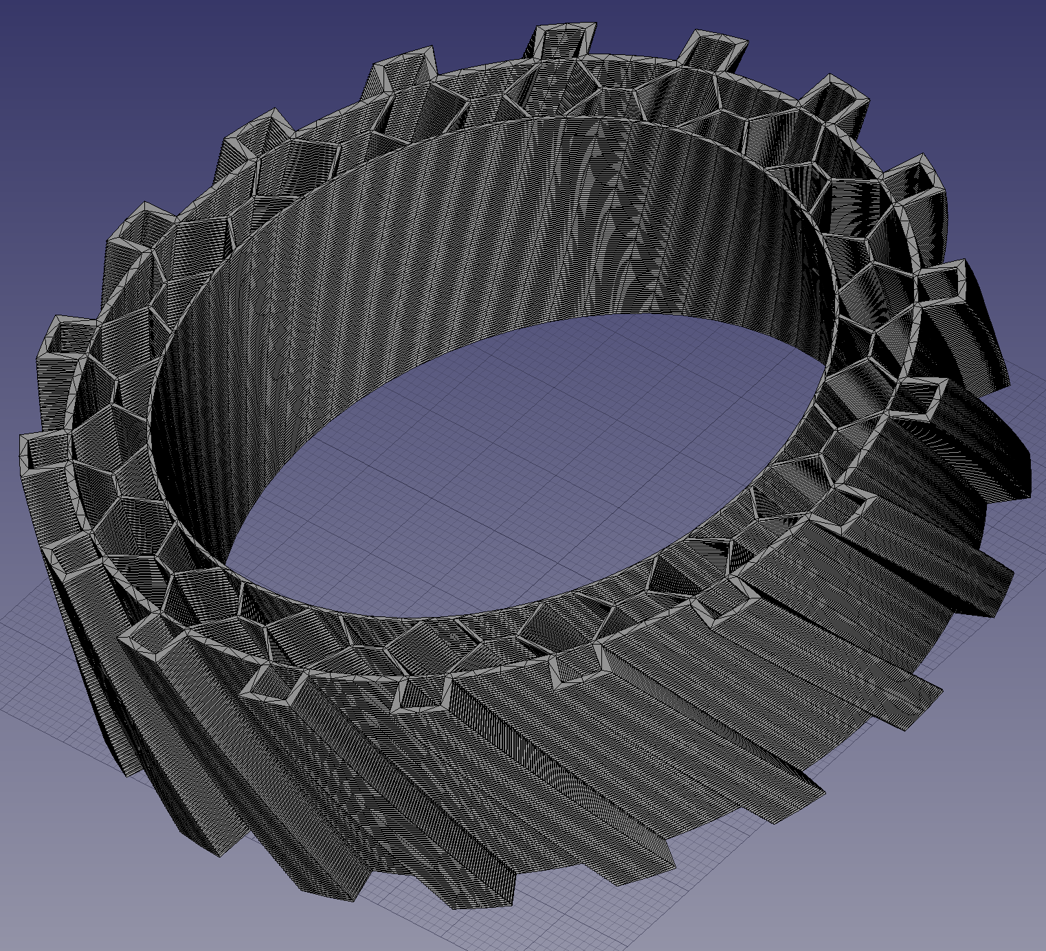
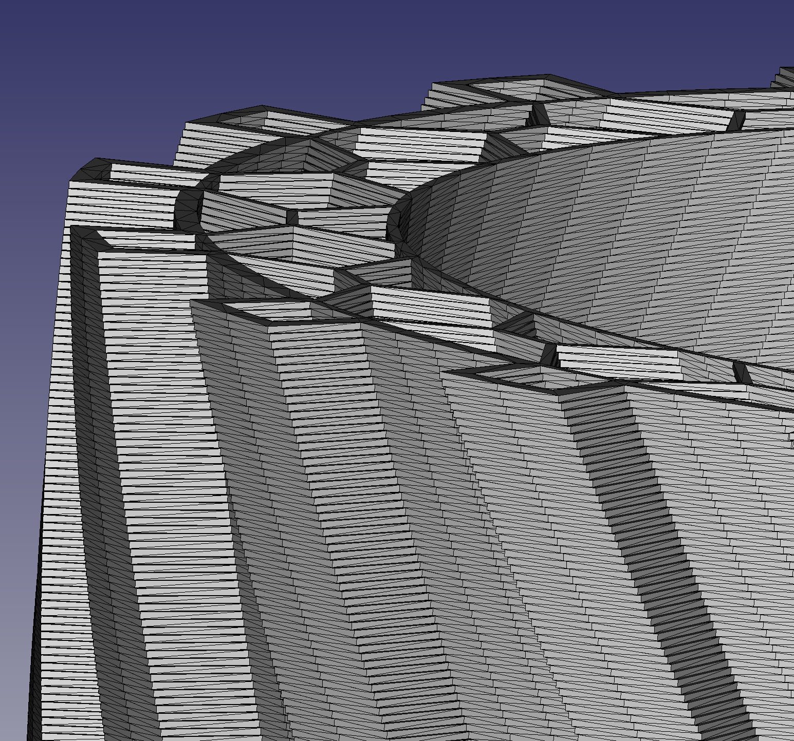
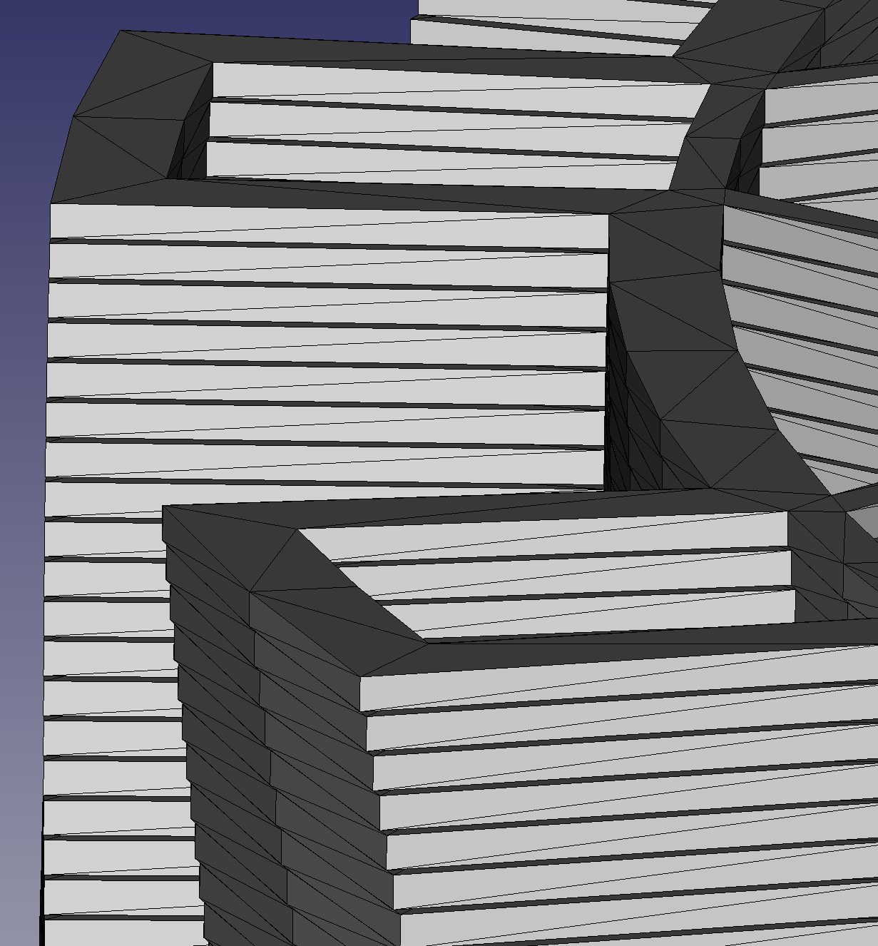
The decision was made to make a helical front tire like the helical rear tires. Because of the round tread, it couldn't be a simple C program that replicated & rotated an STL file. This one performed 96 boolean operations in Blender to create individually rotated layers, over 6 minutes.
Blender has proven useful for final pass booleans, but it doesn't do parametric models, can't import a scene graph from FreeCAD, or have a model history.
![]()
![]()
![]()
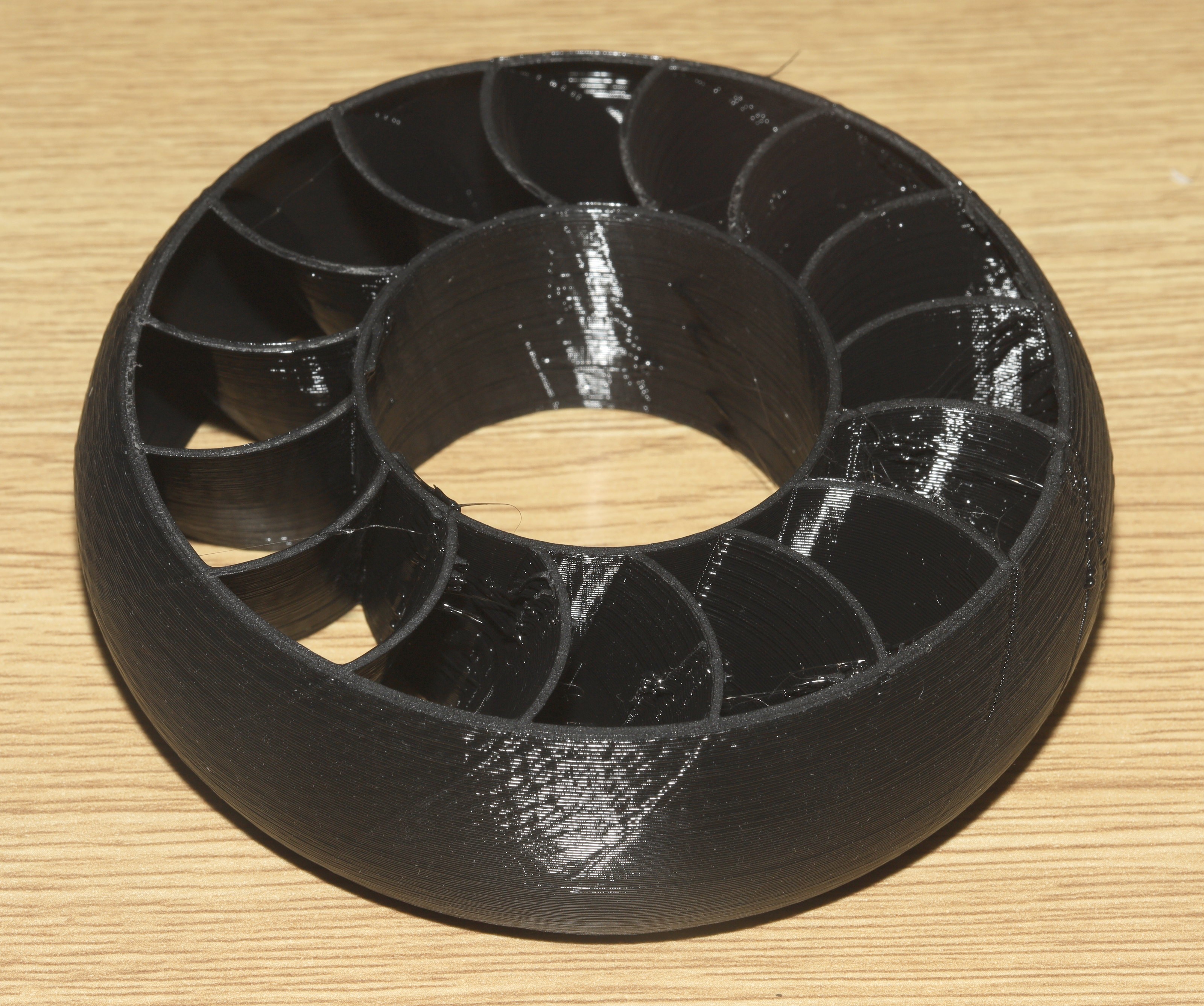
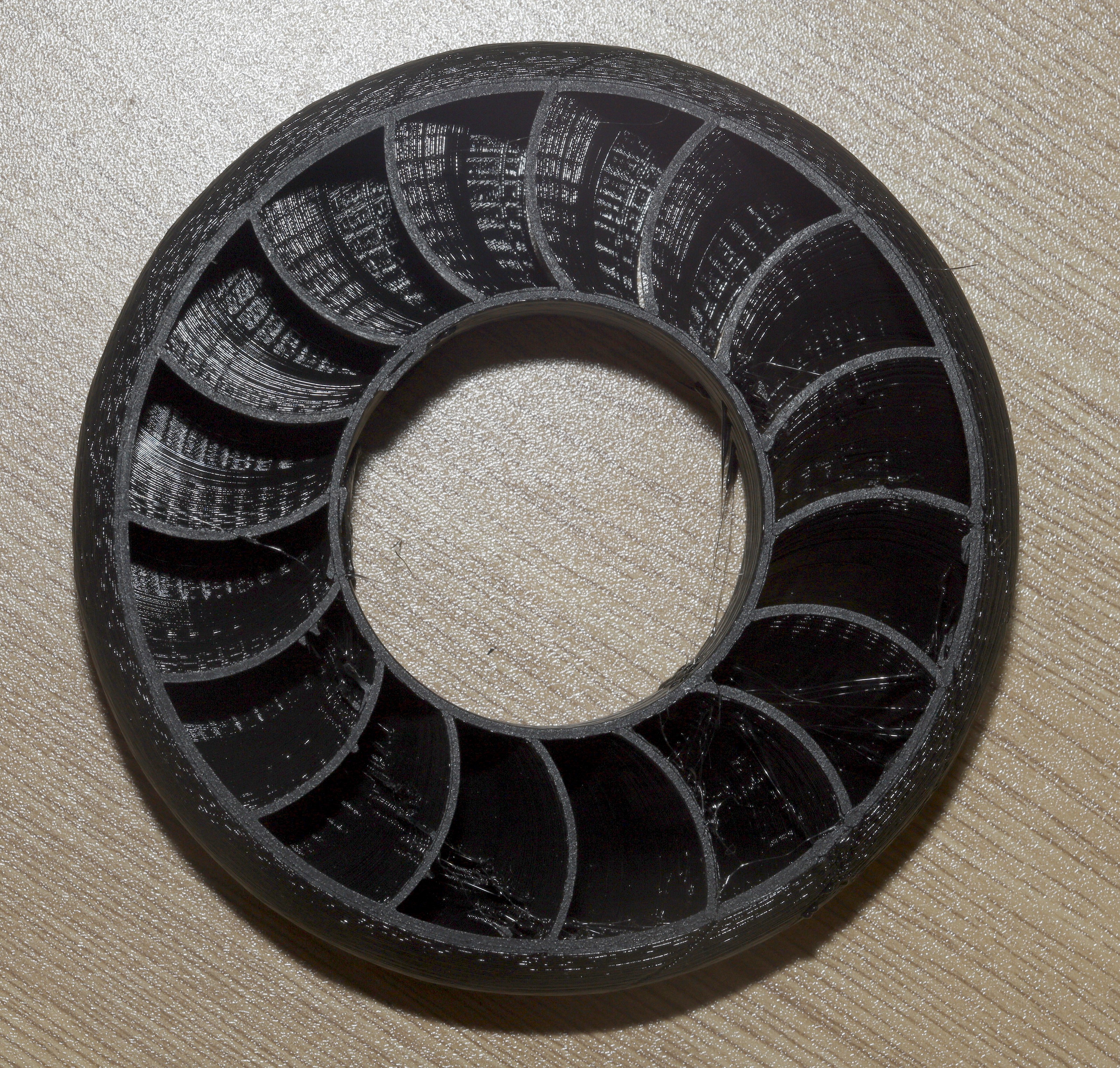
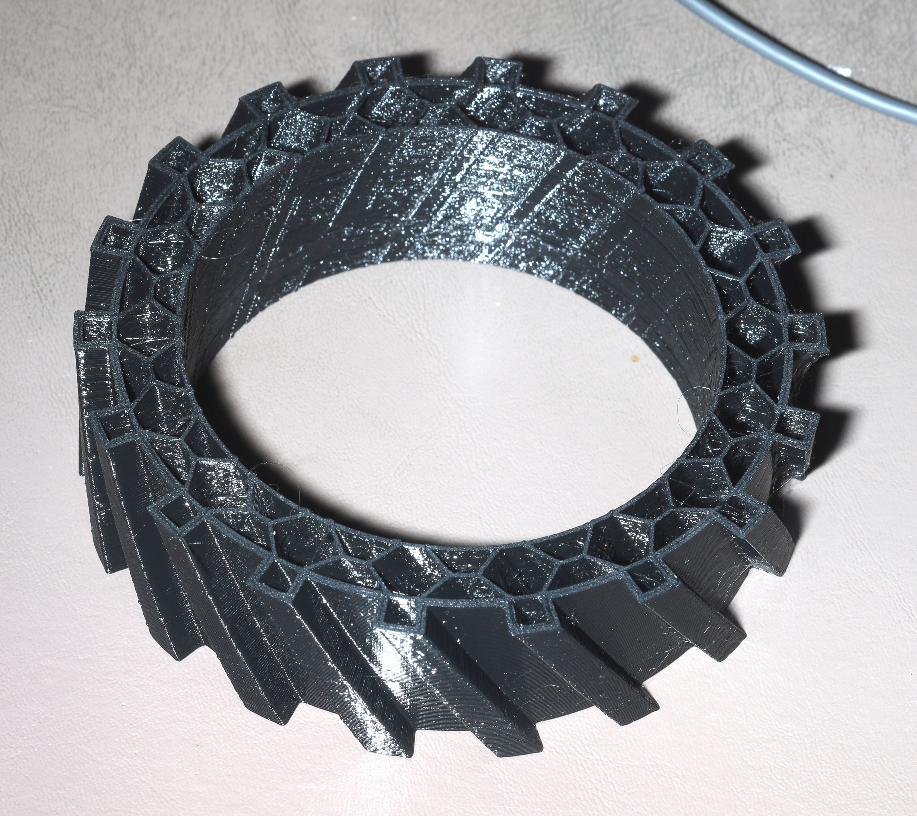
It only took 3 tries & $4 of filament to get it close. They're never the perfect hardness.
-
High vis controller
08/27/2021 at 20:03 • 0 comments![]()
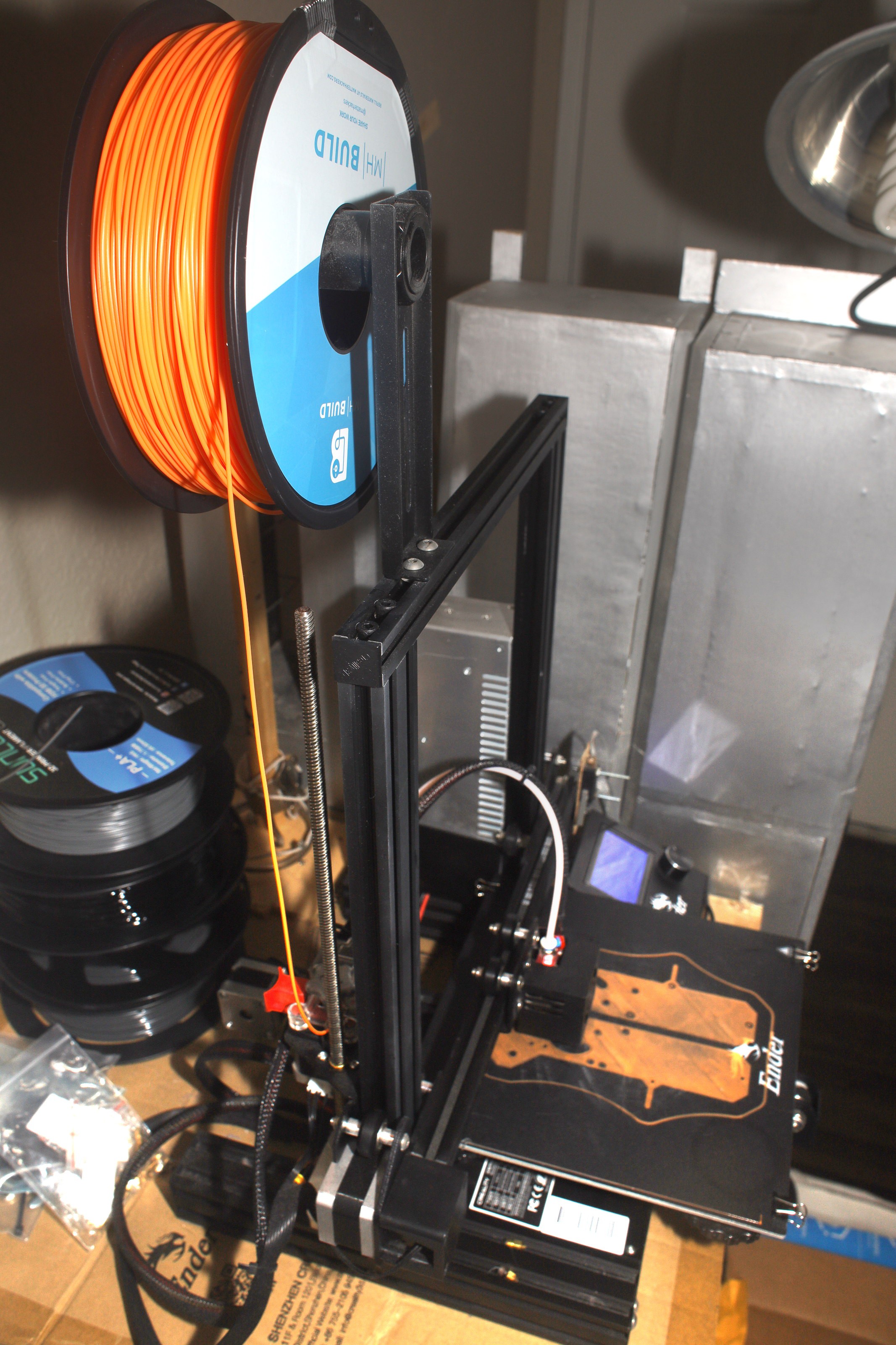
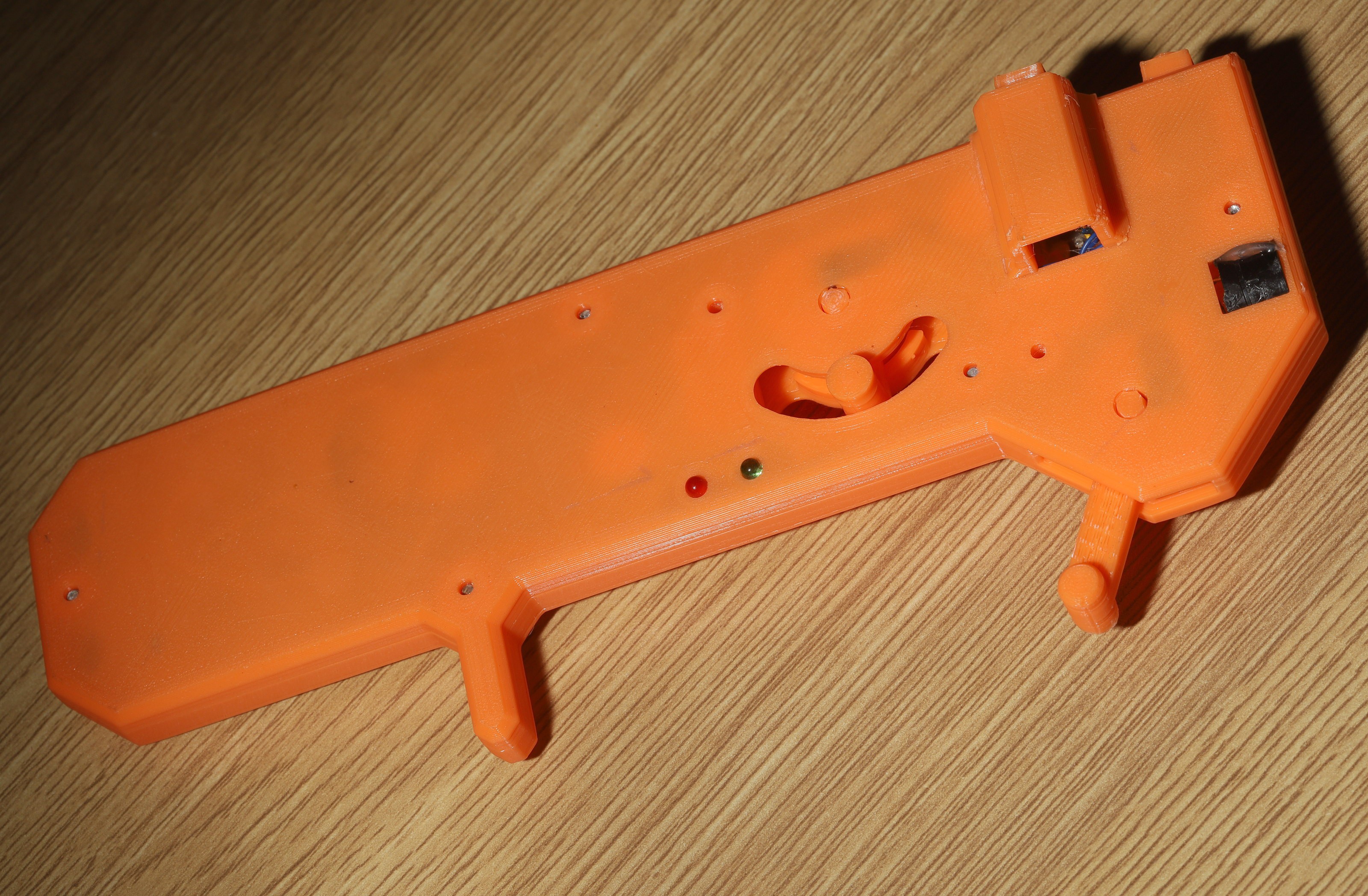
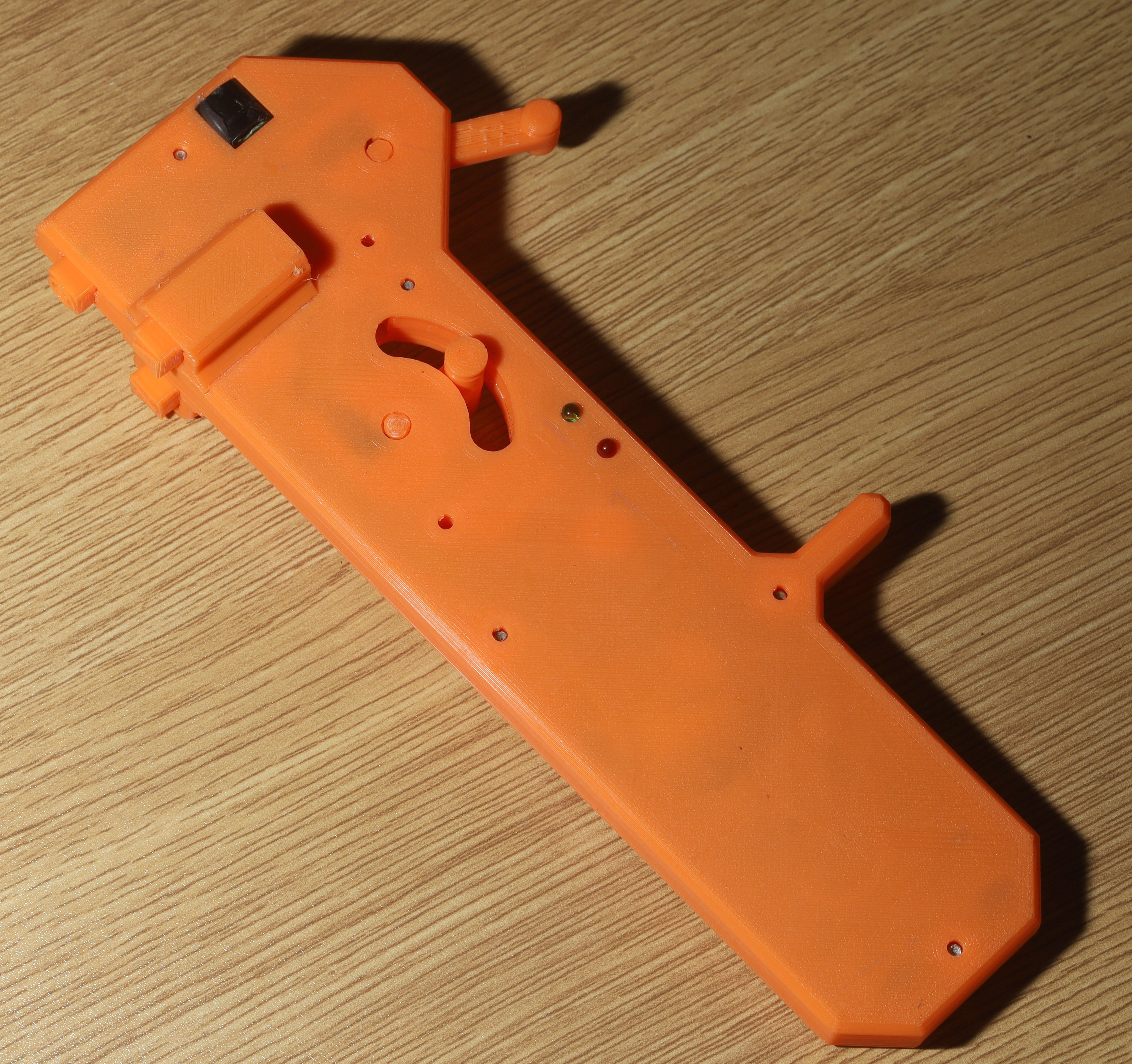
The lion kingdom finally upgraded to colored filament. A high vis paw controller was seen as the biggest win from colored filament. Orange was the closest PLA color since there are no high vis PLA colors.
Gootube videos extoll the fluorescence & shine of a $60 filament vs a $18 filament, but lions seriously doubt there's any difference in fluorescence. It's going to be covered in sweat.
It was time to model in all the lessons of the last 6 months. It got a few more M2.6 screws. The decision was made to skip M1.7 screws, since the amount of PLA required to make a standoff would nullify a smaller screw.
![]()
The original grey controller was quite soiled.
![]()
This was the 1st deployment of the clicky momentary pushbutton. What a great click it is, but it was absolutely worthless when running.
![]()
![]()
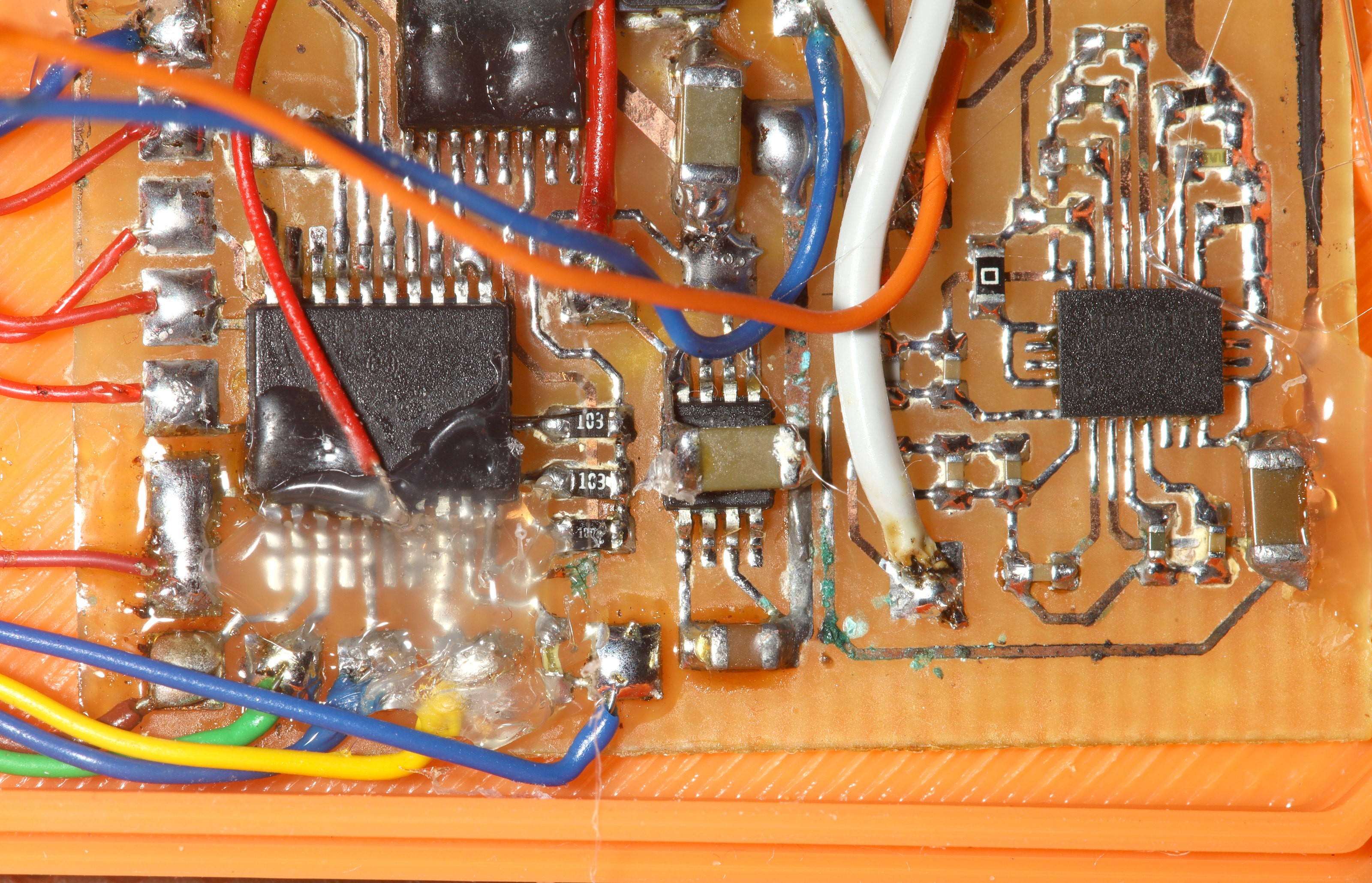
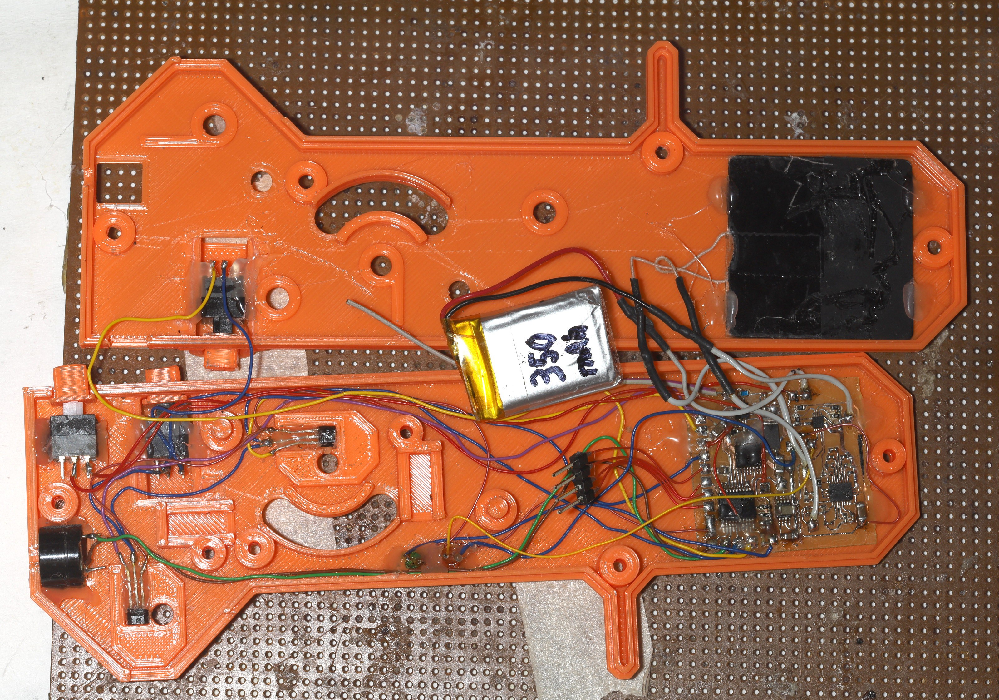
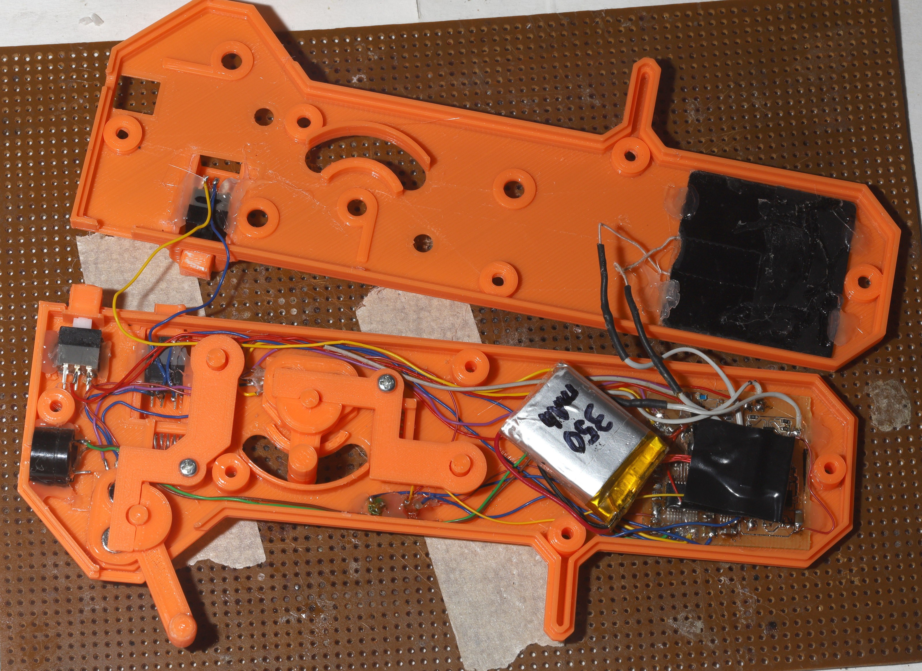
The electronicals had extreme water damage. It surprisingly only entered the clamshell facing away from the lion, a retrograde motion of the normal sweat path.
![]()
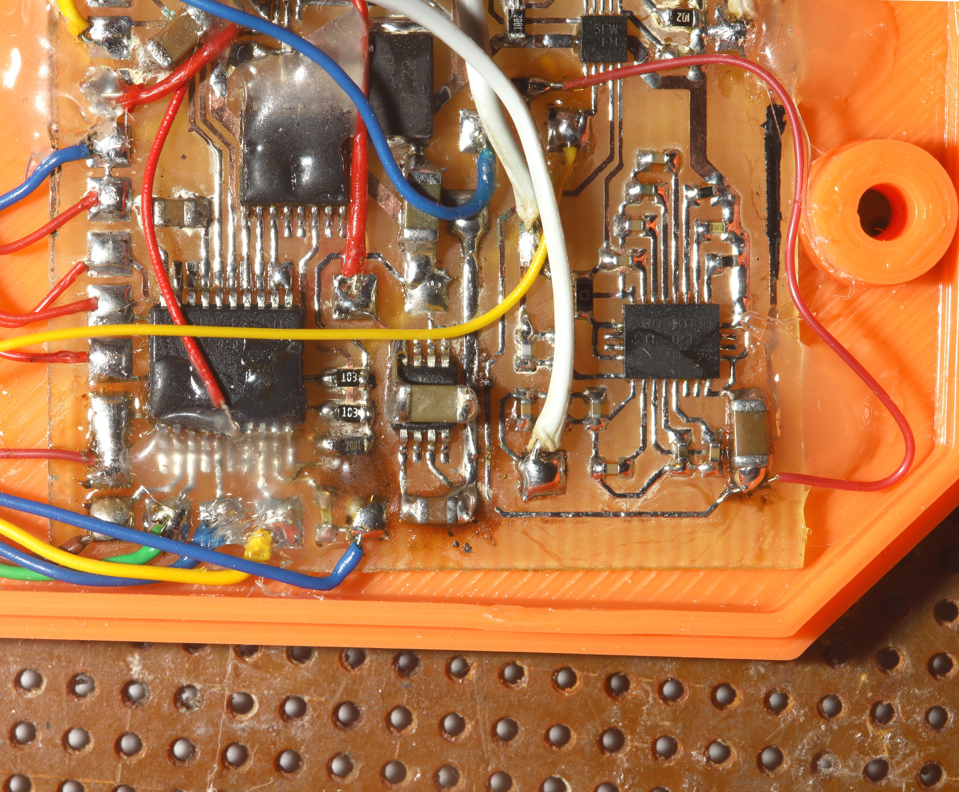
A trace perished & got a bodge wire replacement. The other traces got a tinning. This board is in the twilight of its years.
![]()
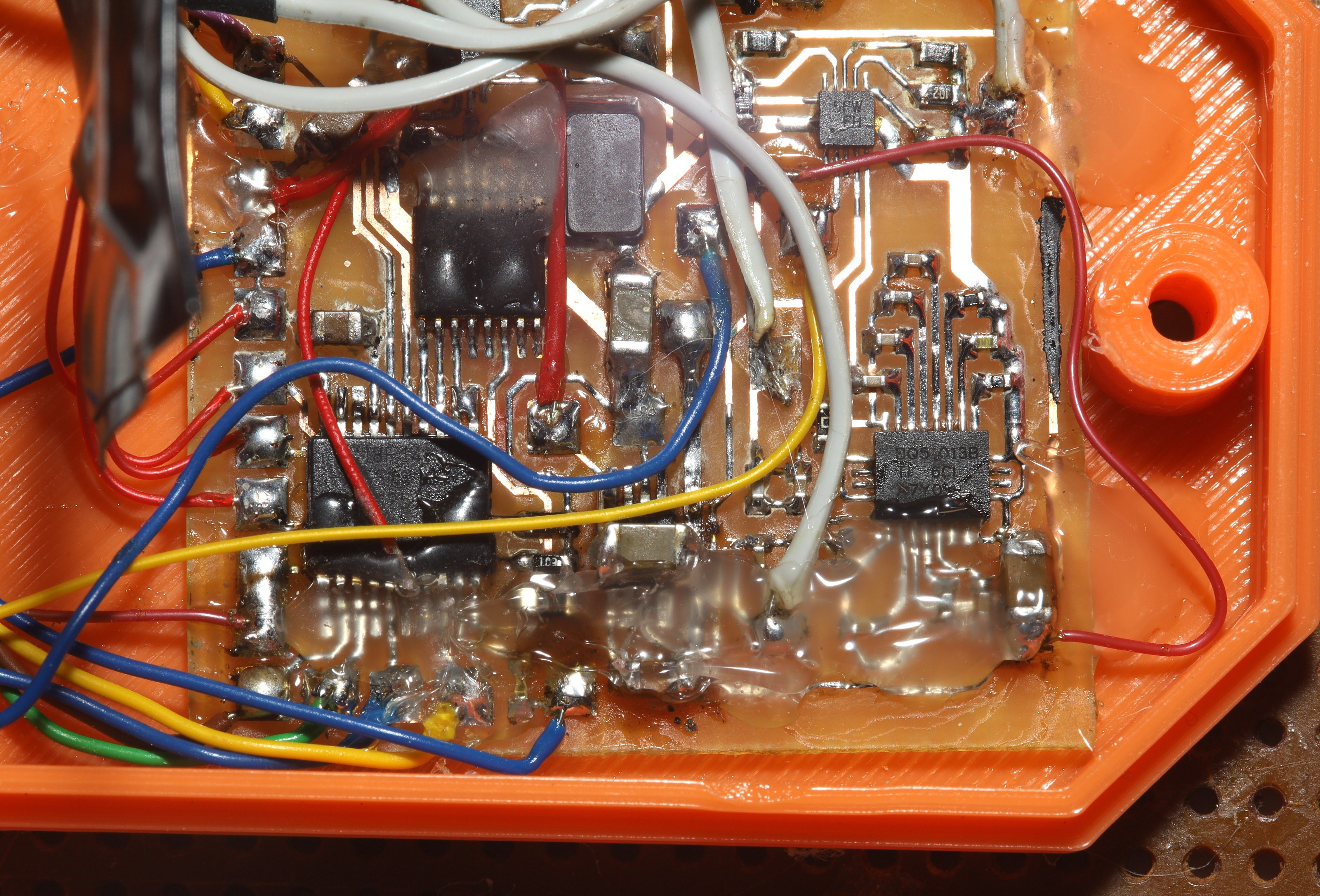
Then it got a hot glue potting.
![]()
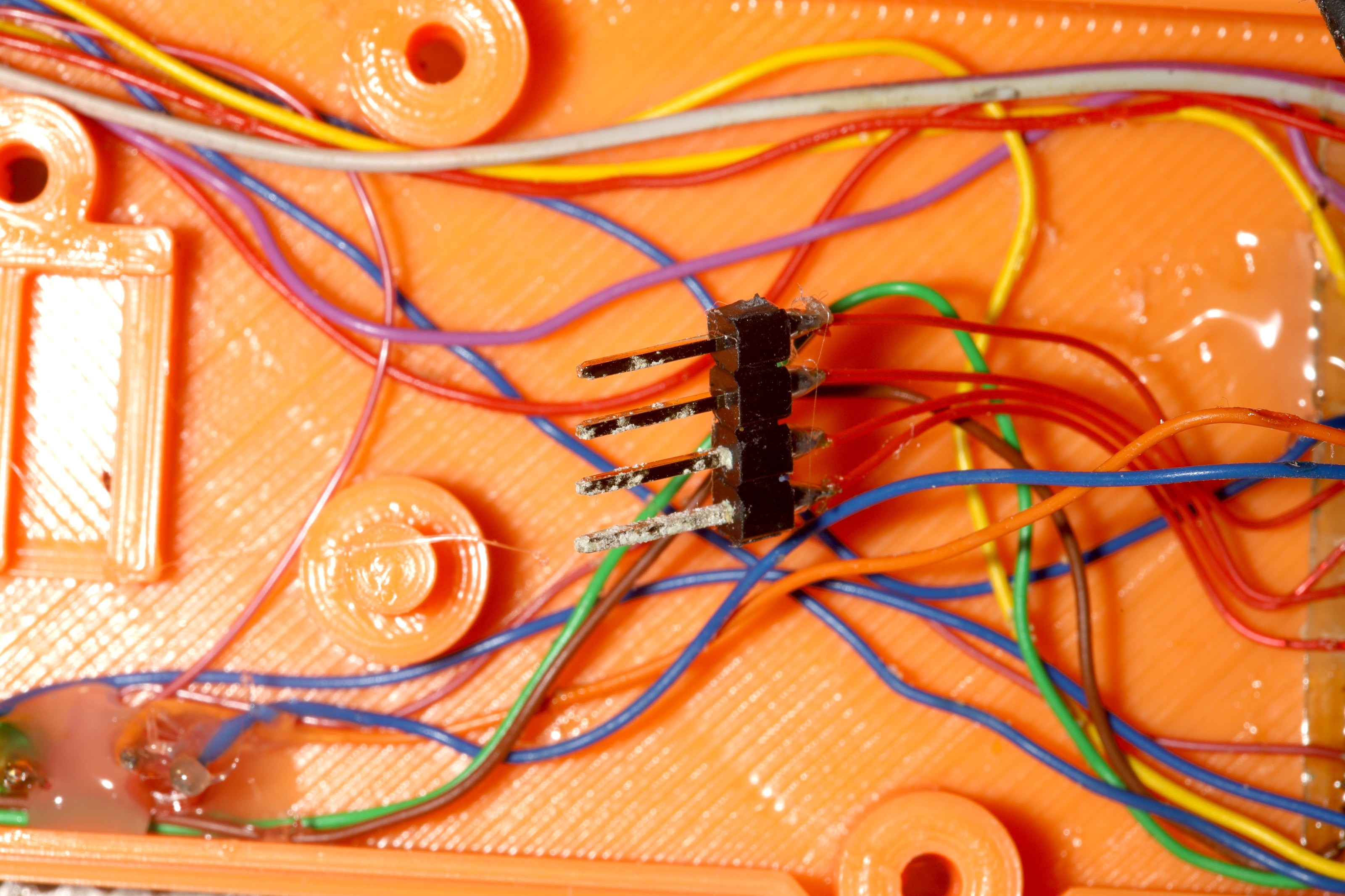
A few wires got replaced. There were 3 hours of damaging a wire to replace a wire, going around the board.
![]()
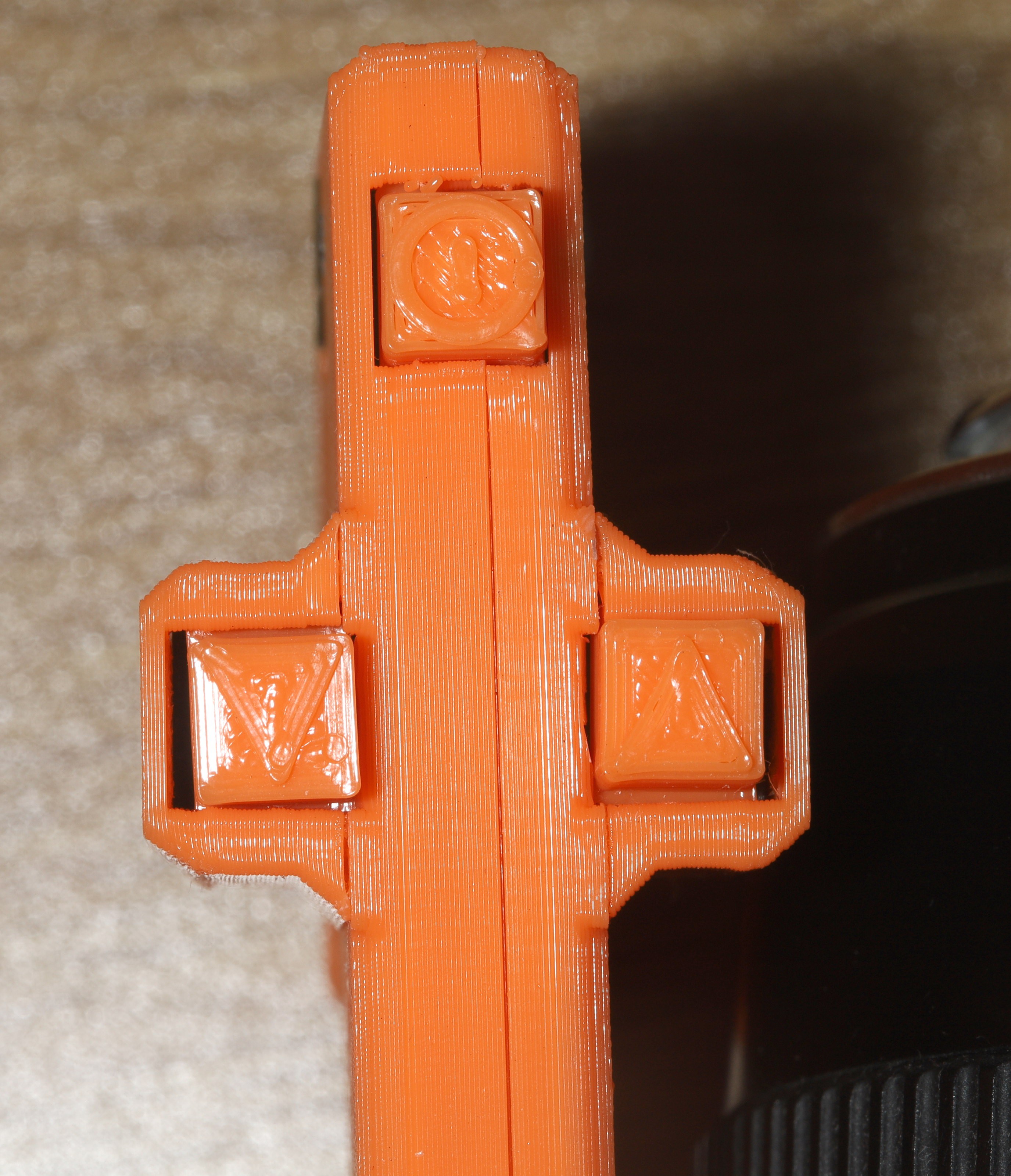
The mechanicals were an epic disaster. It seems the orange build series filament does better at 200C than 210C. At 210C, the layers were expanding randomly. Tolerances were also way off, from bed leveling deviations. The mane problem was making sure there wasn't too much of a gap between shafts & bushings. Screw holes were too big.
After reprinting a few parts, scraping off some material, the joysticks started working. The 2 levers need bigger shafts & bigger cross sectional areas to ensure they only move on 1 axis. The spring being underneath is trying to twist the 2 levers.
![]() The tolerances were so bad, the buttons were loosy goosy but managed to not fall out.
The tolerances were so bad, the buttons were loosy goosy but managed to not fall out.![]()
It took a heroic number of prototype guesses, but this is the 1st to be truly ambidextrous. There's no way to make adjustable controls without making it into a brick, so the only way to adjust anything was to make guesses. The lion kingdom has come from a time when an ambidextrous controller was impossible, to something that barely worked with loss of circulation, to something that truly works.
![]()
This controller got a rounded throttle stick to address some of the chafing.
![]()
Another feature was a shifting of the sound frequencies to try to make it louder, but this speaker has more of a comb filter than a single resonant frequency. Sadly, it looks more like a happy meal toy than a high vis controller.
-
Giant wheels
08/26/2021 at 05:33 • 0 comments![]()
![]()
![]()
![]()
![]()
![]()
![]()
![]()
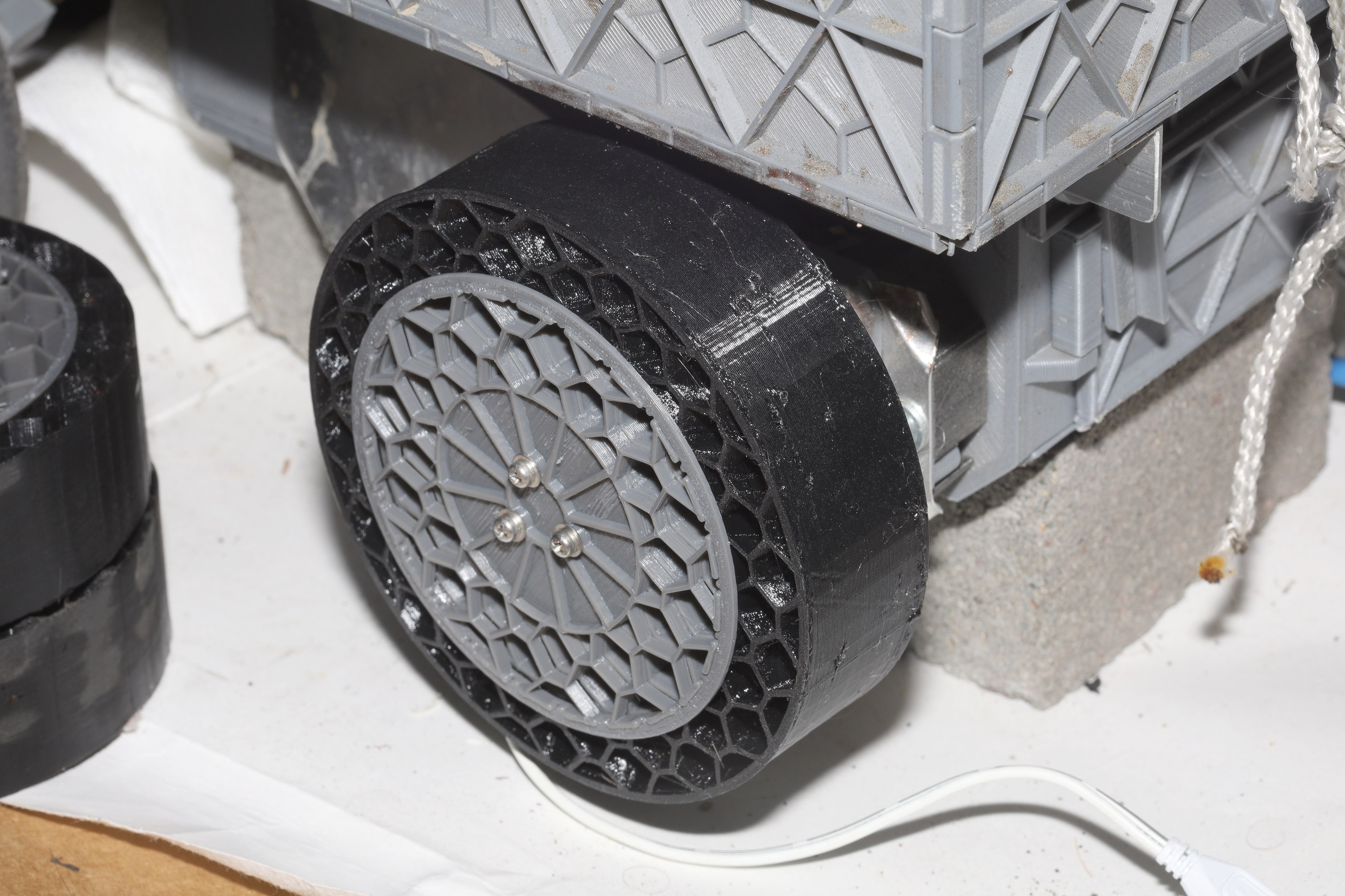
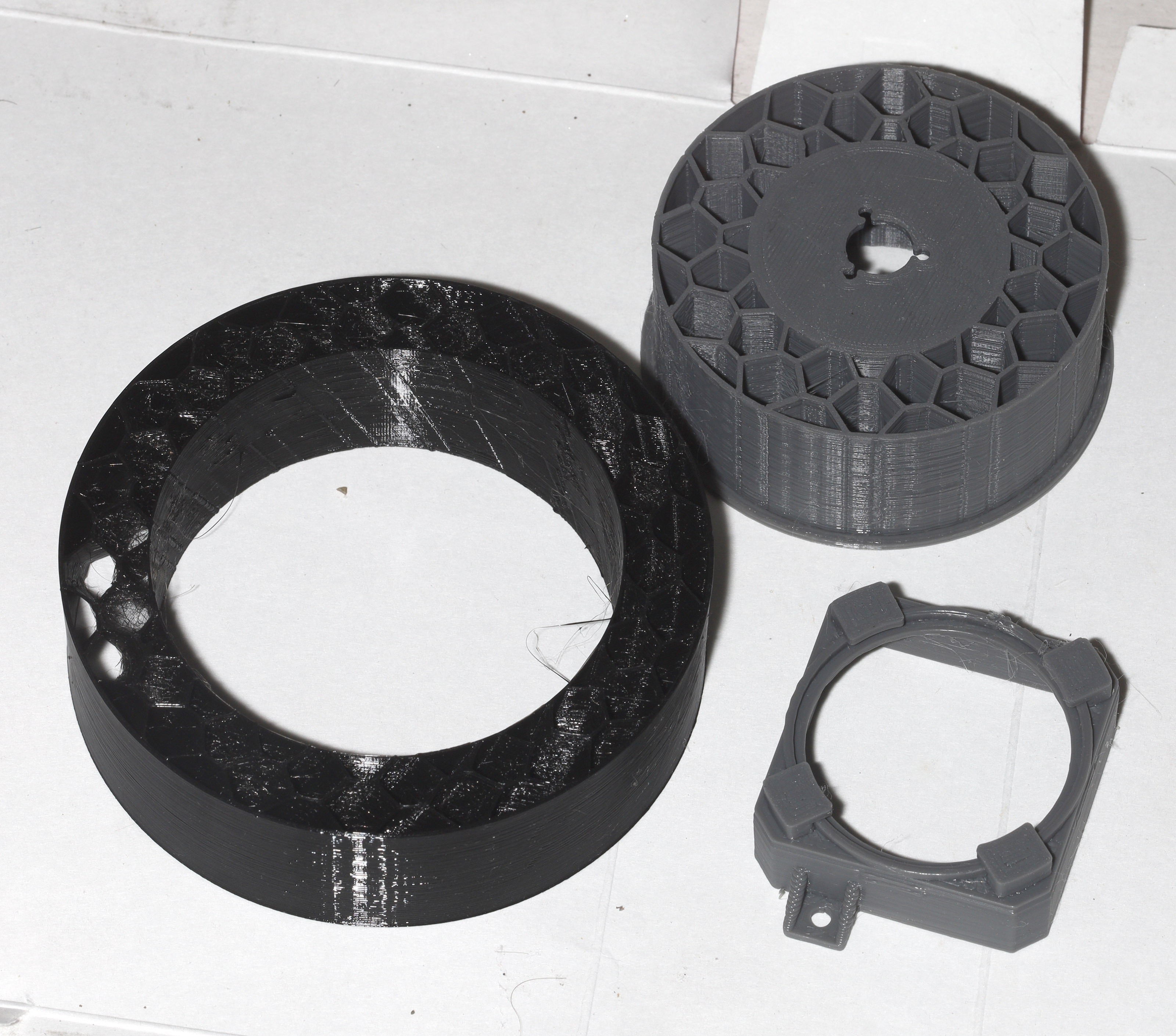
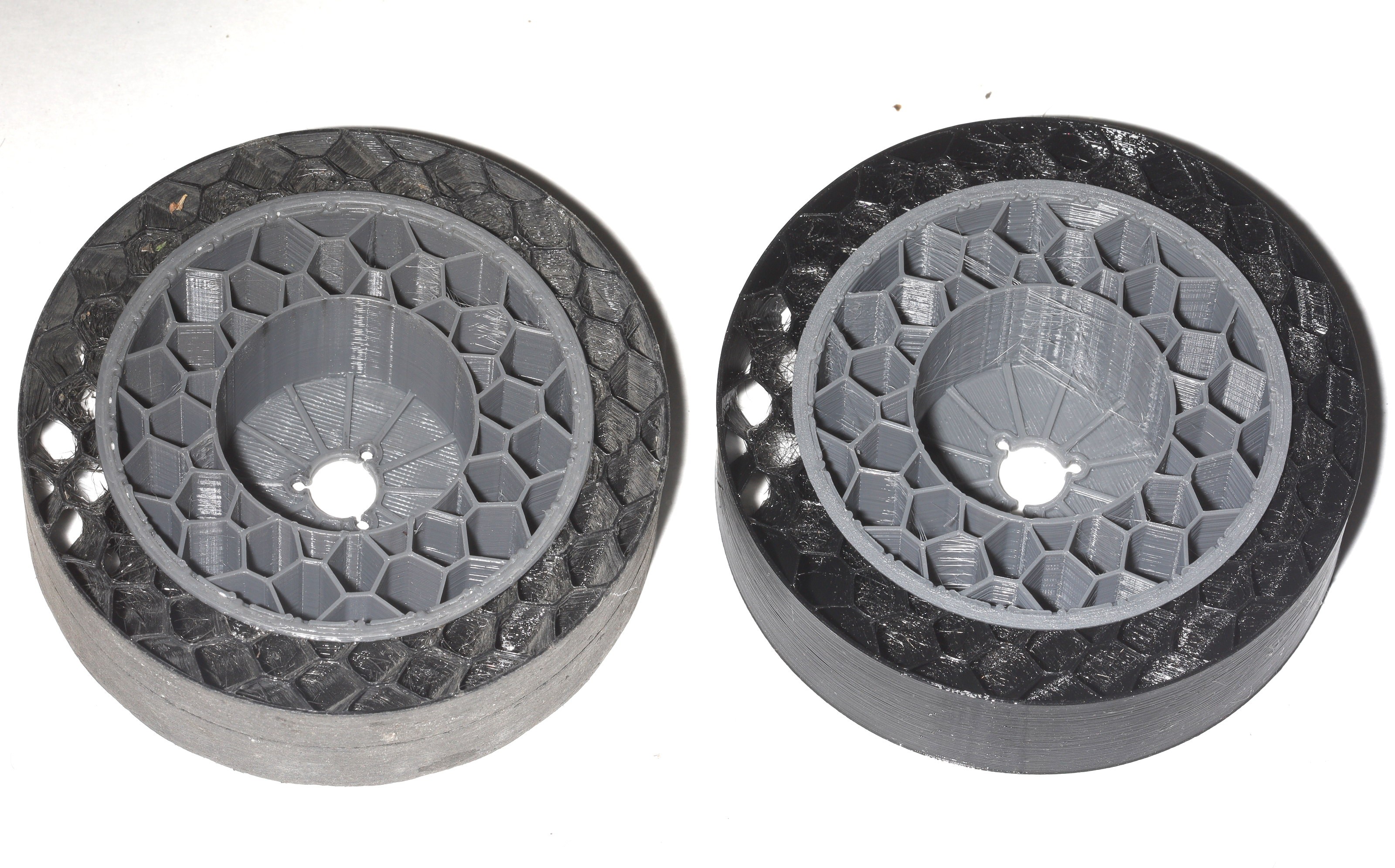
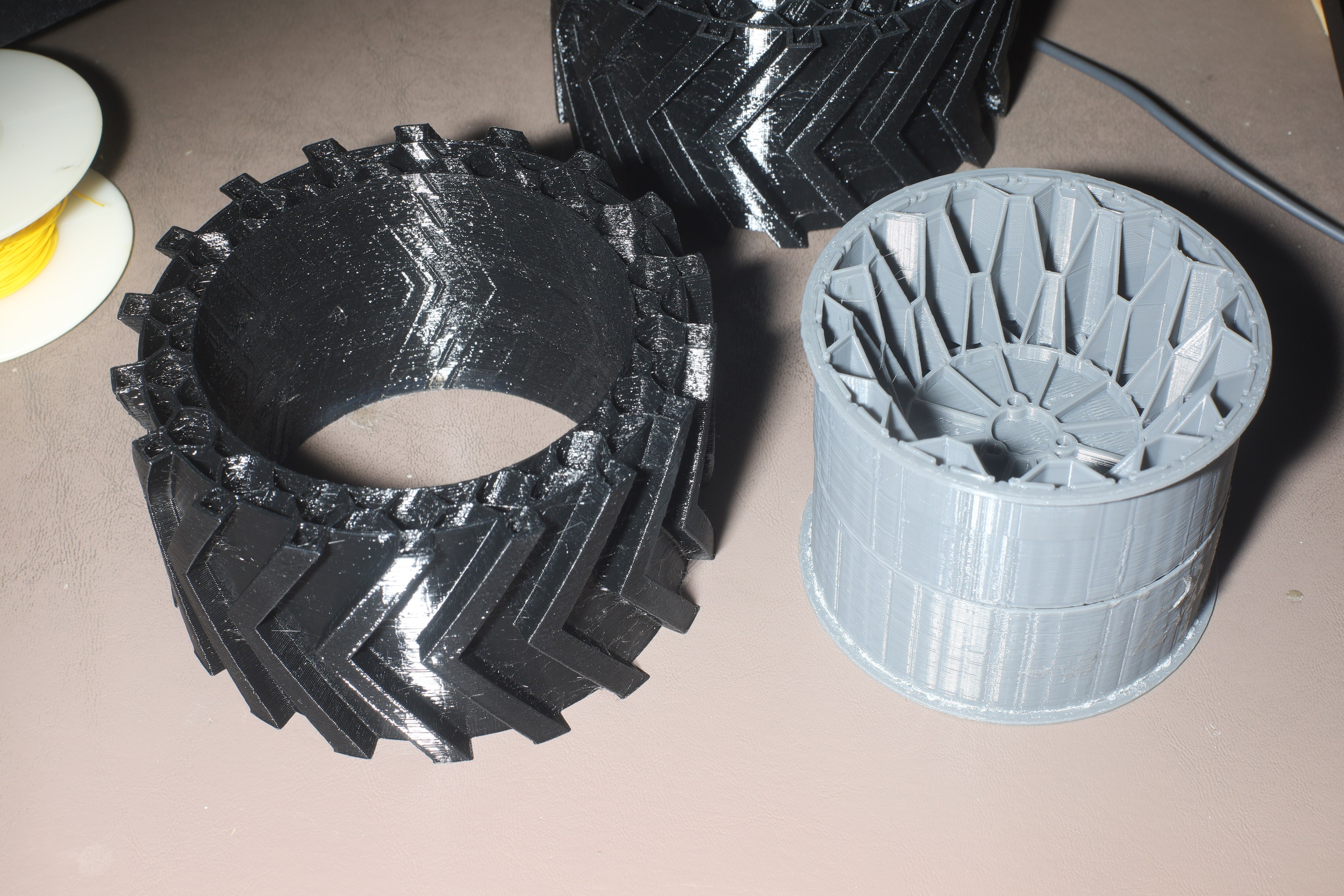
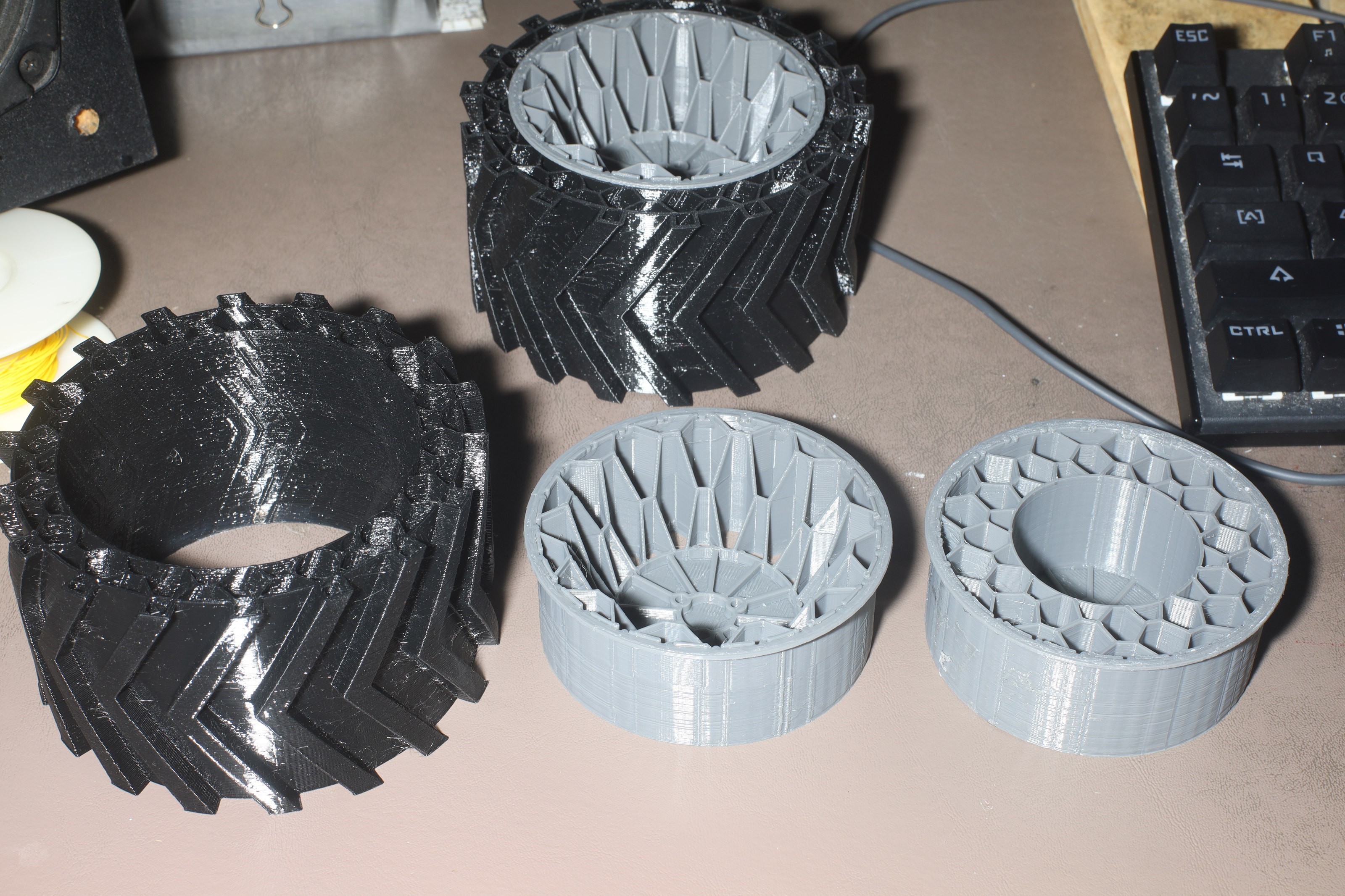
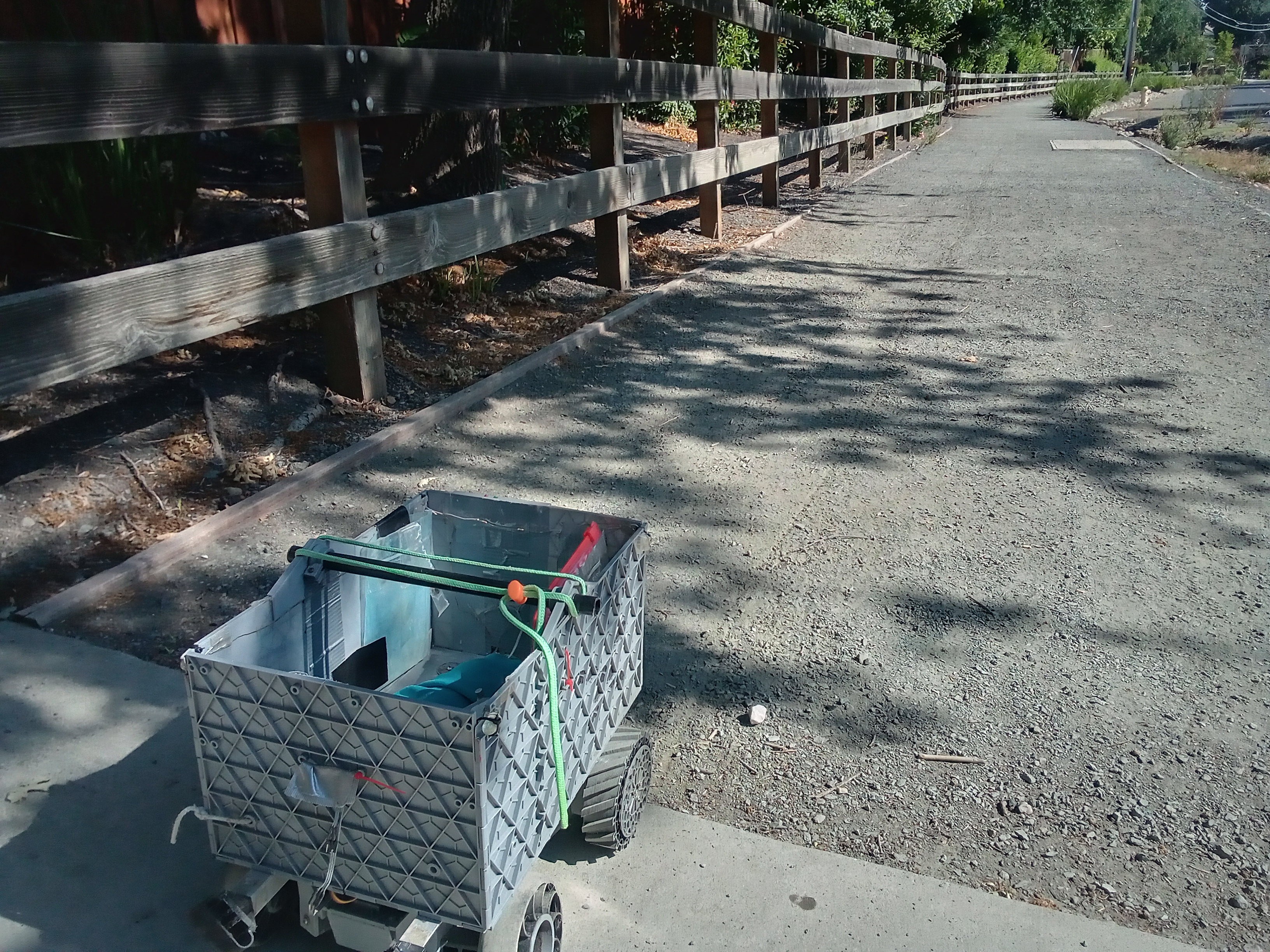
After 48 hours of printing, the 1st 60mm wide wheels arrived. If these can't get around on gravel, nothing below a scooter can. It immediately became obvious that they're hard to install. There's no way to see the motor holes down those wide hubs.
There's no easy way to detach the hubs from the tires so they can't be glued. They're so wide, it's going to be really hard to steer. The original lunchbox was 290mm across. These are 320mm. The next tires should be 45mm wide, at most. They should also have 5mm more TPU, since the tread pattern is not flexible.
These use a 10mm honeycomb + 5mm tread to allow the same hubs to fit the smooth tires. It was later decided printing all new hubs was more convenient than changing the tires on the same hubs. Obviously, they're only going to be on when an offroad drive is planned.
The original lunchbox tended to have its hubs crack where the right angles are. The hex hubs have a lot less material in the key right angle, but benefit from wrapping around the motor. The hex could be extended all the way to the bolts, but it would be expensive.
It might have been easier to stick the original lunchbox tires on, but they had less range & were expensive. The worst case 3D printed tire is cheaper than a $5 lunchbox tire.
![]()
![]()
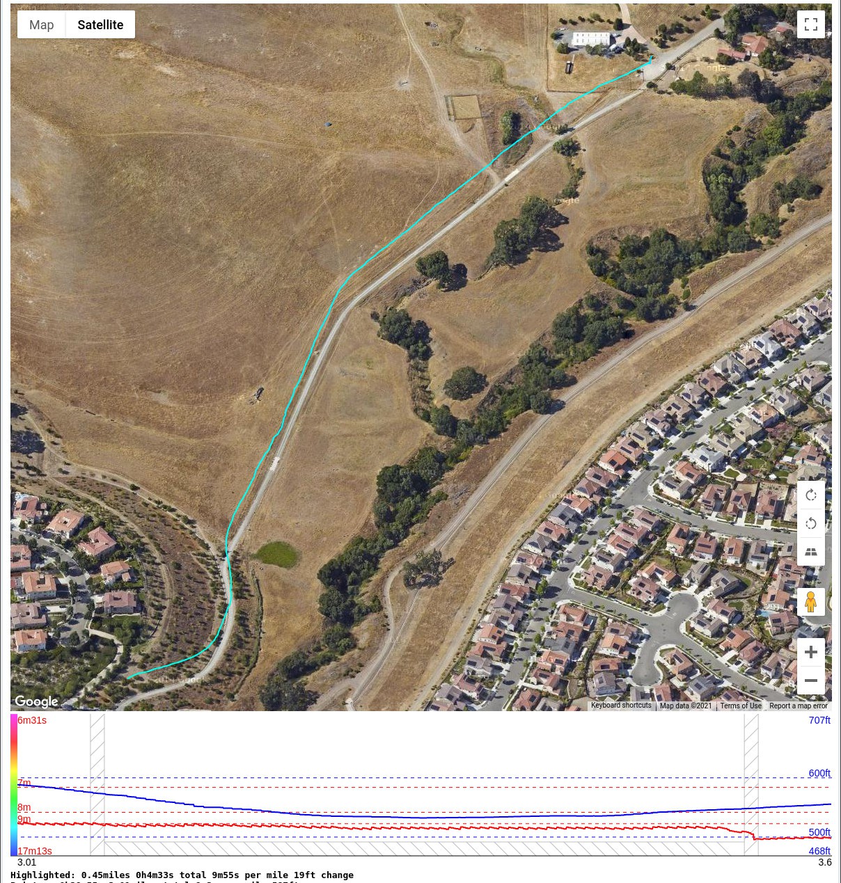
So the 60mm treaded tires made it up the test trail in 4m33s, the same as the 30mm tires. There was subjectively no obvious improvement in traction, but speed highly depends on how much gravel the driver goes over. They didn't materially affect the steering. They might have made the very fastest turns slower.
The mane problem is they had so much mass, they instantly popped the motor's retaining rings off. There are ways to make the retaining rings permanent, by drilling into the motor shafts.
The mane evidence of improved traction is they left much less of a mark than the 30mm tires, so they were pushing forward more instead of throwing dirt back. Another section of trail with less gravel showed them going much faster than the 30mm tires, but it was bugger all distance for estimating speed from GPS. A shift of a few GPS readings makes the speeds equal.
Attention turned to updating the container.
Wider container ribs near the top. Thinner container ribs near the bottom
1mm thick PLA under the headlights.
Smaller holes for headlight zip ties.
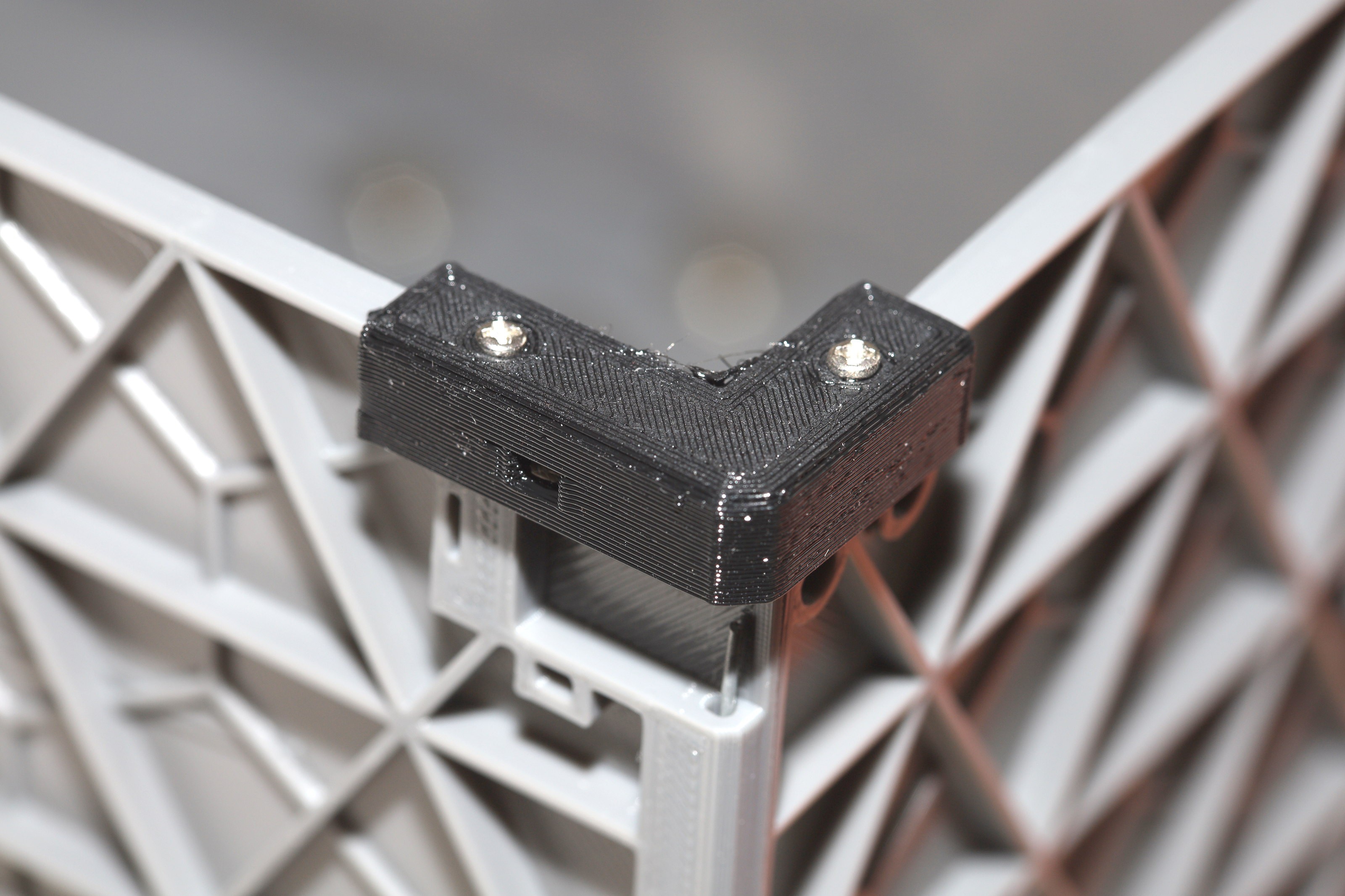
Screw on corner farsteners for the container.The mane problem is optimizing the container mass requires automated bed leveling. There's no way the bed can be within .2mm at every point. The trick with the BL touch is it can't measure changes in the bed leveling caused by the nozzle pressing filament down on it.
-
Helical offroad tire
08/21/2021 at 02:47 • 0 commentsThe problem with lofting between 2 models to get a helix is it constricts the center like twisting a sheet of paper. After much fighting with Freecad's lofting tools, a better way emerged. Extrude a single layer, then make a copy for every layer, with a slight rotation. The 96 discrete models require manipulating an STL file in C. To retain some layer adhesion, it had to use parallel treads instead of V's. Getting a V tread would require moving the treads much closer together.
![]()
![]()
![]()
![]()
Wider tires would be another win for offroading but cost more.
![]()
These got new hubs so they could be swapped in easily. They were adhered with elmer's school glue since Calif* outlawed rubber cement.
![]()
It went up the test trail in 4m33s. The smooth tires went uphill in 5m11s. The smooth tires went downhill in 4m9s. In exchange for this slight improvement, they were much noisier on pavement, despite the helical treads. They actually handled bumps & hit the programmed speed about as good as the smooth tires. The 5mm treads acted just like another 5mm of tire radius.
![]()
They dug a lot more into the gravel. There's a plan to widen the tires, but it requires finalizing on the 15mm thickness & amount of cushioning. Lions can't afford to iterate on the wide tires.
-
Polecam 3
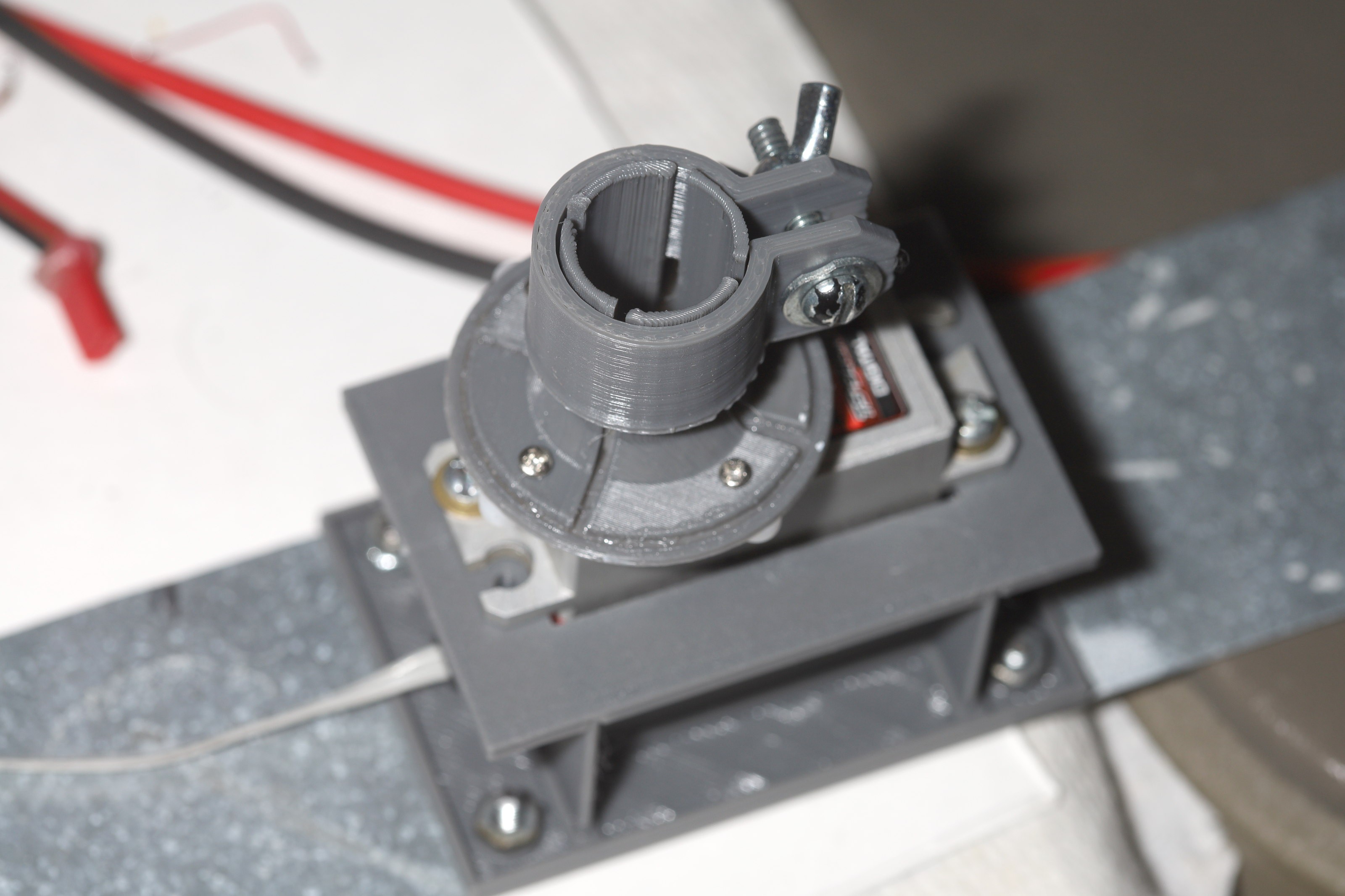
08/20/2021 at 02:25 • 0 commentsA trackstar finally began its new life as a 360 stepper motor.
![]() The 1st step was taking out the MOSFETS to free up space & directly connecting the 3 motor phases.
The 1st step was taking out the MOSFETS to free up space & directly connecting the 3 motor phases.![]()
![]()
Then came chopping off the encoder lugs.
![]()
Then came grinding off the titanium stopper. The gears got cleaned & relubricated.
As a stepper motor, it needs to commutate really fast to get 1 revolution every 4 seconds.
At 5V, it burns 500mA. At 6V, it burns 1A & gets hot. Its key advantage is it doesn't need to be powered to stay in 1 place. Timelapse mode still requires the full current, so it can't be given the 1A. The standby current when it doesn't move is 50mA. It doesn't have as much torque as the stock servo.
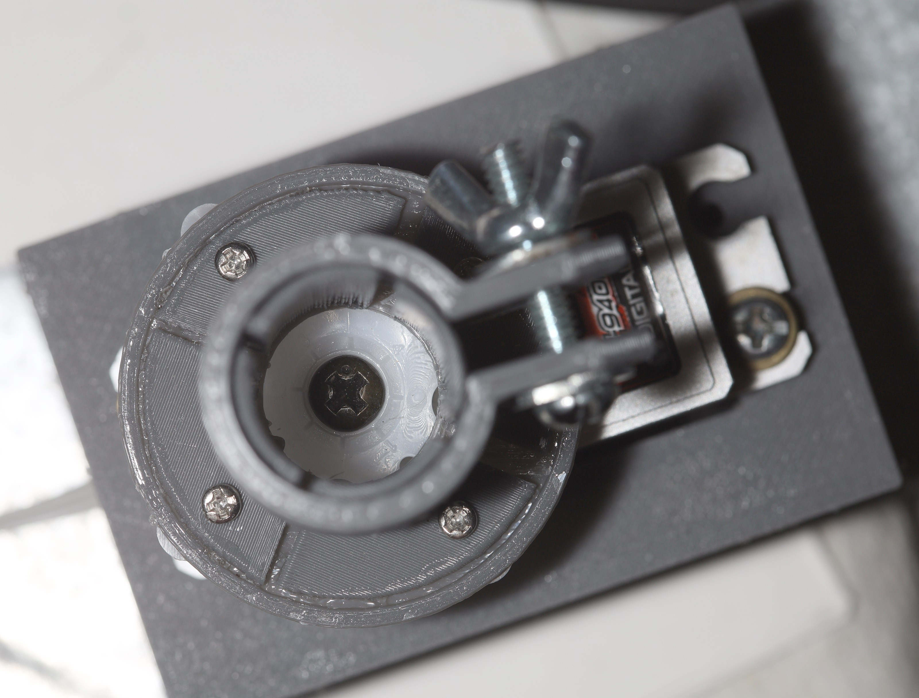
A new servo mount was printed.
![]() This has a stiffness problem when screwing in the servo. The risers should go all the way past the servo screws. The bottom plate should extend beyond the longer risers. The servo hole should be narrower.
This has a stiffness problem when screwing in the servo. The risers should go all the way past the servo screws. The bottom plate should extend beyond the longer risers. The servo hole should be narrower.![]()
The carbon fiber adapter evolved to be more flexible & use less material.
![]()
Servo must be screwed in before carbon fiber. There should be enough torque for clothing to not jam the rotation, but you never know.
While this turns very smoothy with very little power, it's still a horrible design. It uses an L6234 for the previous motor to directly drive the servo motor, even though the servo already had the electronicals for driving the motor. It would save a lot of space to reprogram the servo to do all the motor control & have a much smaller board outside just read the radio. The mane compromise was to give up empty space for less time programming.
The C8051F330 in the servo can be programmed with an arduino & the pads are pretty obvious.
![]()
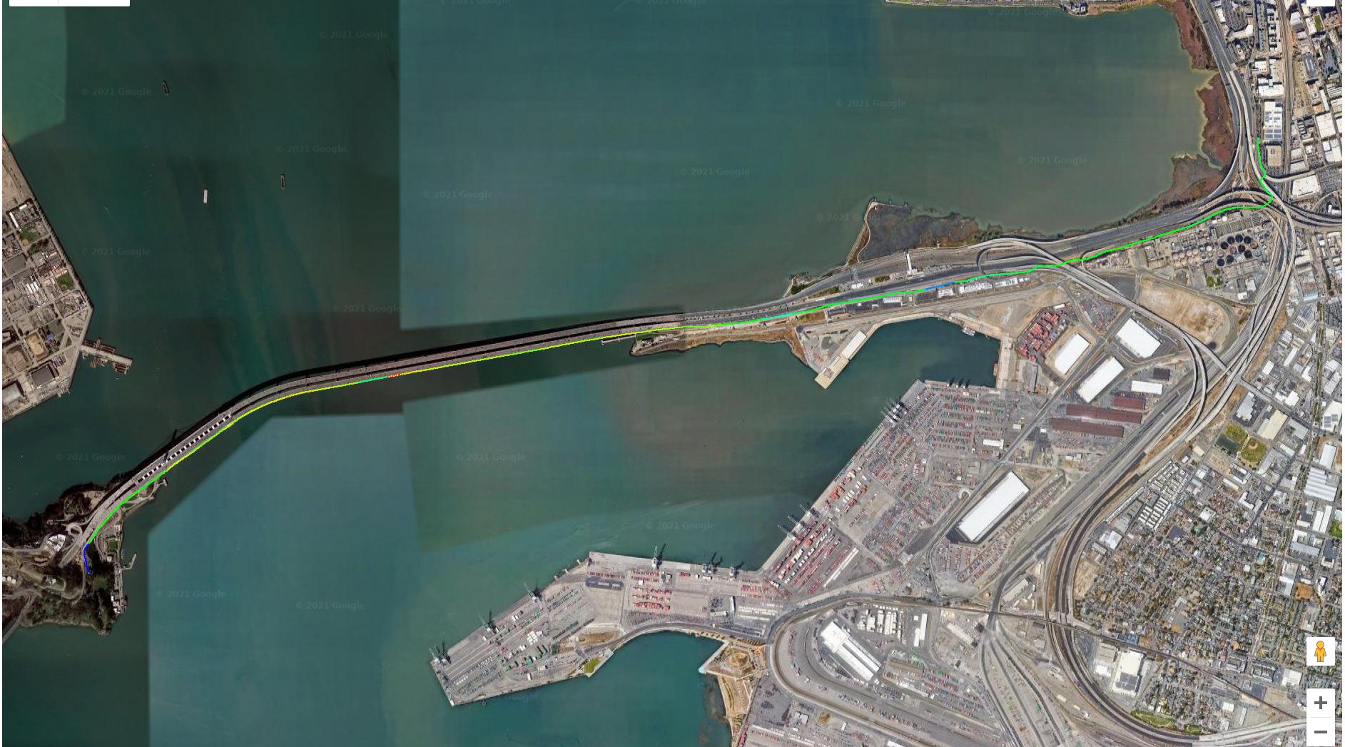
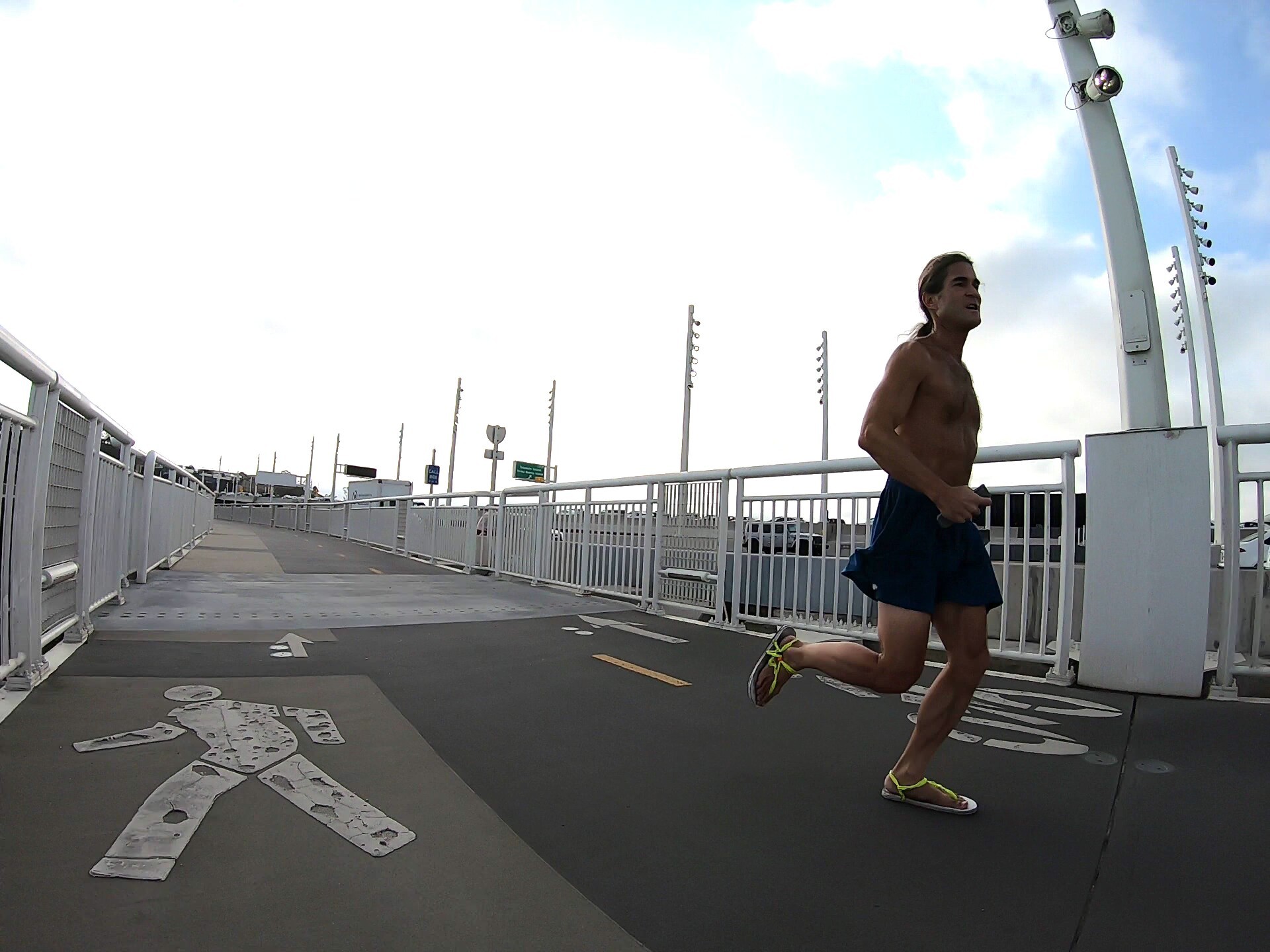
It easily did 7 minute miles going downhill, with the wind. The lion was wiped out after only 2 miles at this speed. The full 20 minutes considered a tempo run were at 7m34s/mile downhill, with the wind. It was disappointing.
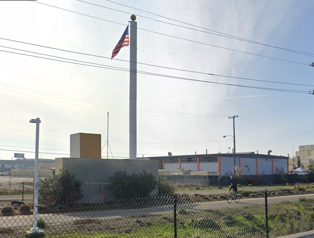
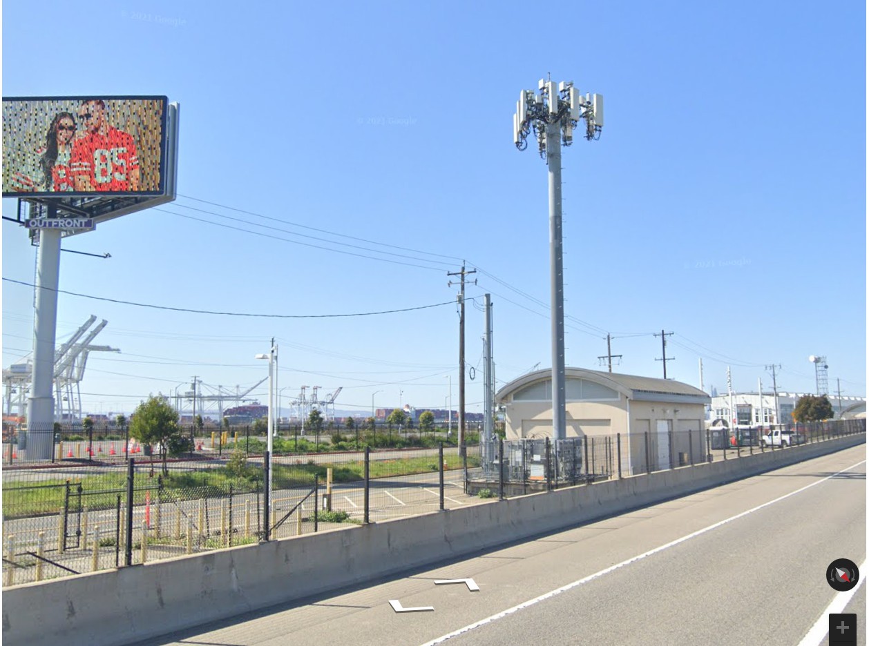
There was renewed jamming of the radio by phone towers, despite all the amplification. These phone towers may have been closer. There's only so much amplification a lion can afford.
Then, the new panning servo raised the camera a hair, which caused new oscillations. It got underdamped surprisingly when driving over raised paint.
![]()
![]()
![]()
-
15mm helical tires
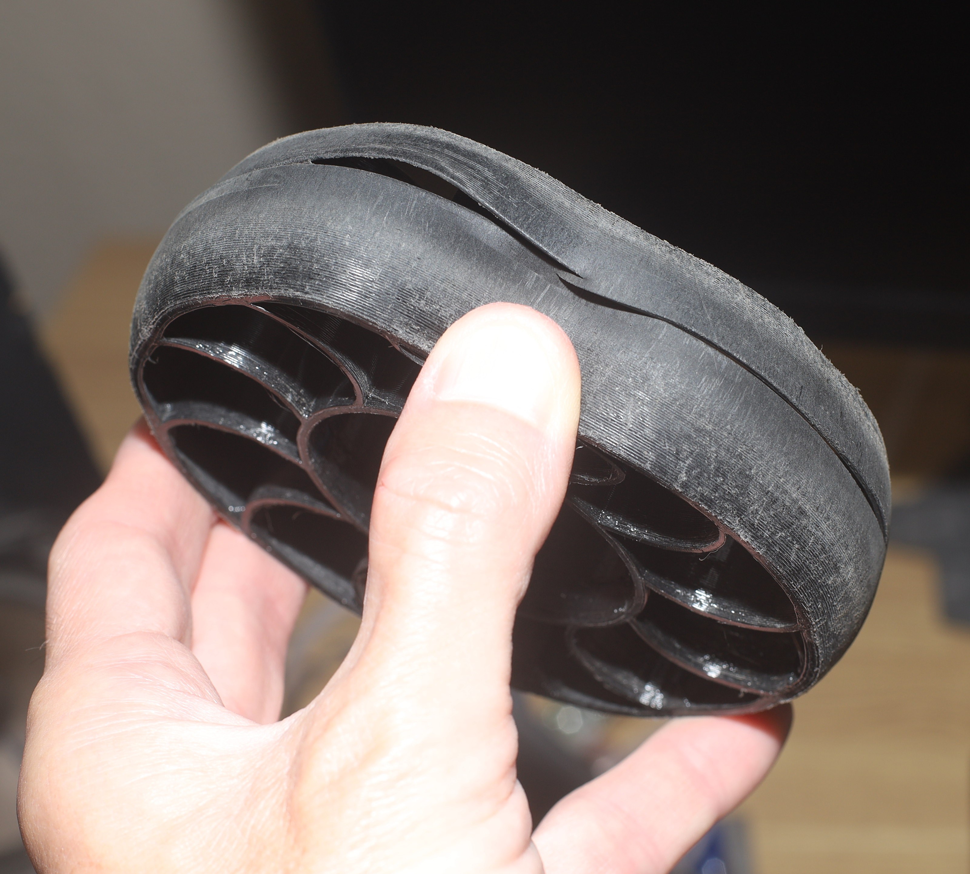
08/04/2021 at 03:53 • 0 commentsThe last tires got very high efficiency but couldn't handle bumps. They also got noisier & noisier at slow speeds because the interior structure was perpendicular to the motion. Eventually it was almost as bad as a gearbox, so the next step was a helical tire. They also got slightly thicker to try to handle bumps better. The material is still under $2 per tire.
![]()
The trick with Freecad is lofting a perpendicular tire 1st, then rotating the 2nd outline. It also requires lofting in the part designer. Lions have no idea how the part designer tools became the standard in Freecad when every other CAD program is happy to rely on the simple part tools.
![]()
![]()
![]()
![]()
Some really bad .32mm layers. Not sure why the PLA looked much worse than the TPU.
![]()
![]()
There was a new castillated mechanism for attaching retaining rings. It made most aspects much easier but gluing was more tedious.
![]()
![]()
The castillations make the hub look cracked ahead of its time.
![]()
The old wheels were truly bashed.
![]()
![]()
![]()
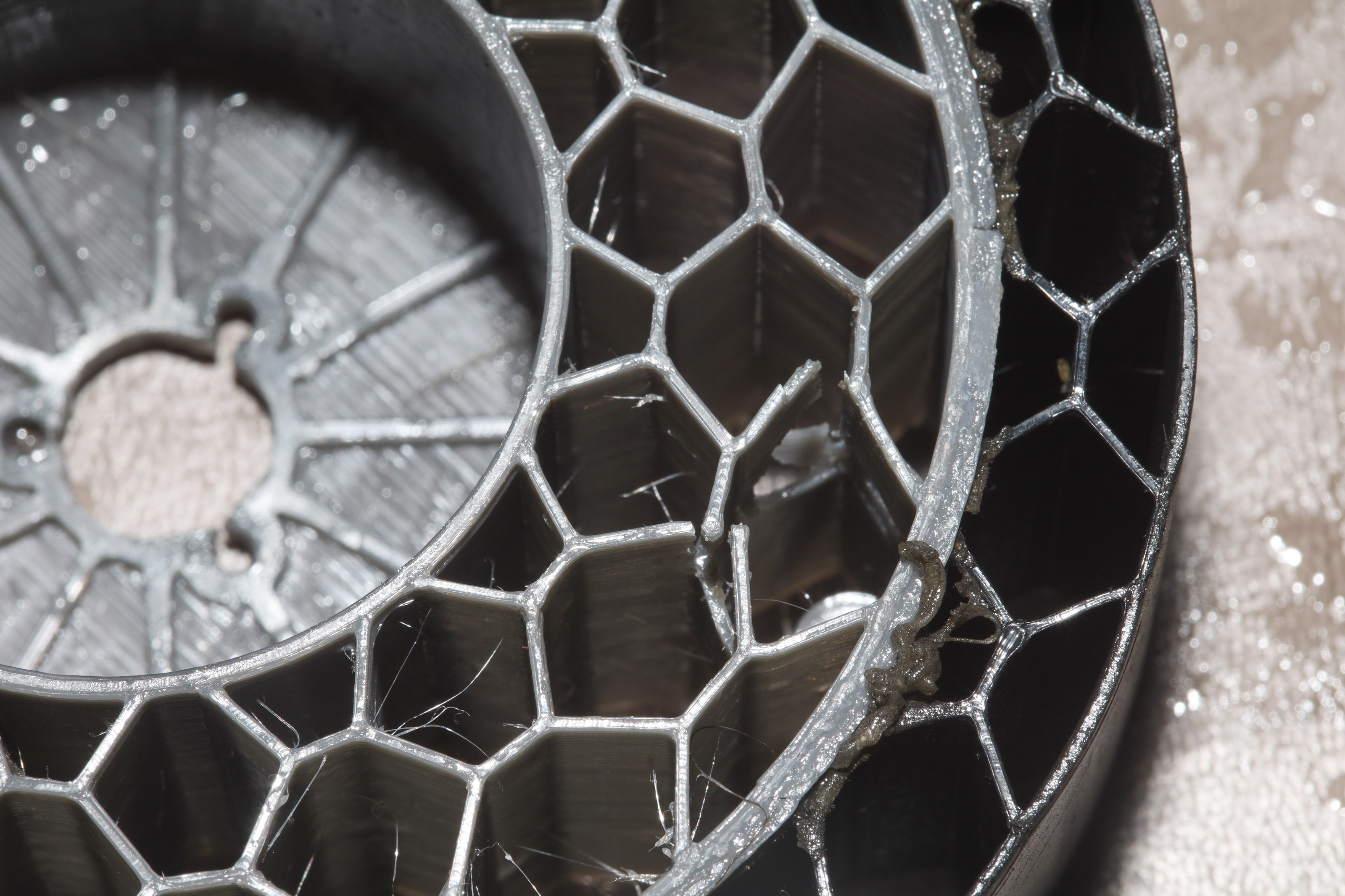
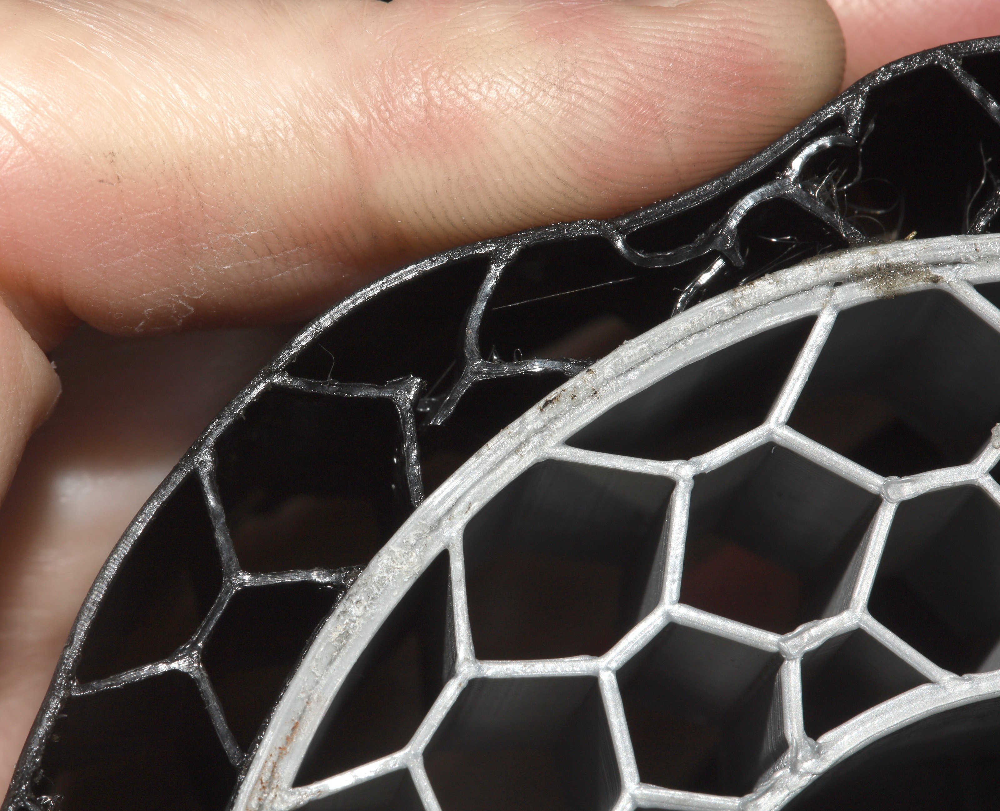
The 1mm tread & .5mm TPU honeycomb cracked in many places.


 The tolerances were so bad, the buttons were loosy goosy but managed to not fall out.
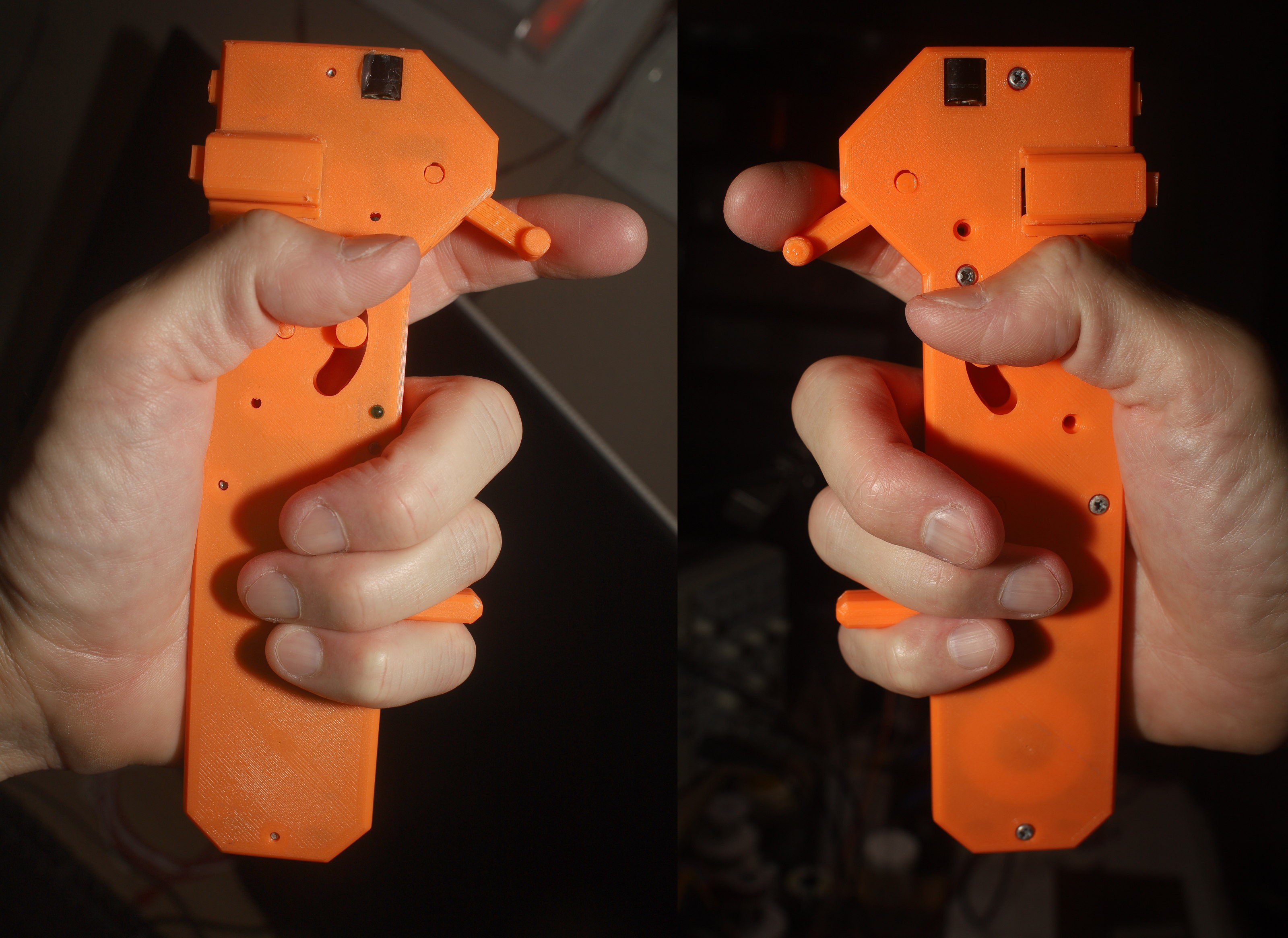


 The 1st step was taking out the MOSFETS to free up space & directly connecting the 3 motor phases.
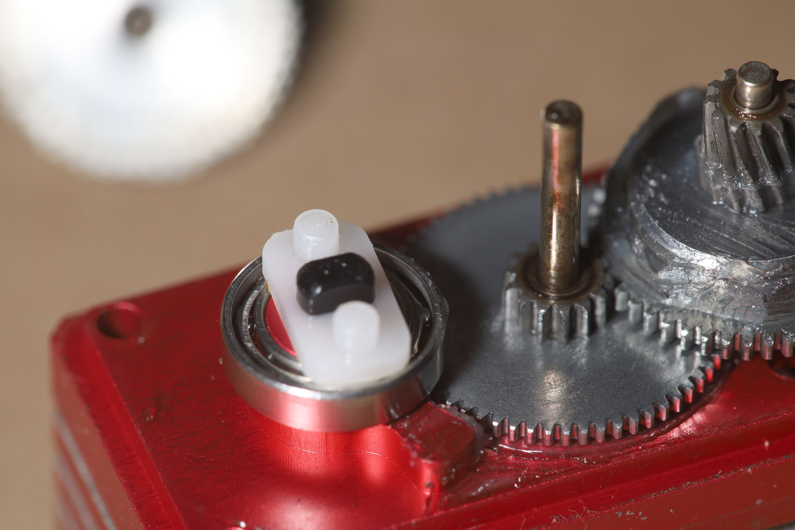
 This has a stiffness problem when screwing in the servo. The risers should go all the way past the servo screws. The bottom plate should extend beyond the longer risers. The servo hole should be narrower.