lion mclionhead
-
Wishlist
07/27/2021 at 07:43 • 0 comments`There is a desire to update the remote control with a lot of M1.7 screws around the clamshell. This would make it more waterproof & improve the sensor alignment. The problem is screw holes are a buster to model in Freecad.
The new controller would be 10mm longer to fit in the right paw, since right paw driving has proven more ergonomical than left paw driving.
Ideally it would be orange, but multicolored PLA remanes too expensive. Orange is the closest PLA comes to a high vis color.
-
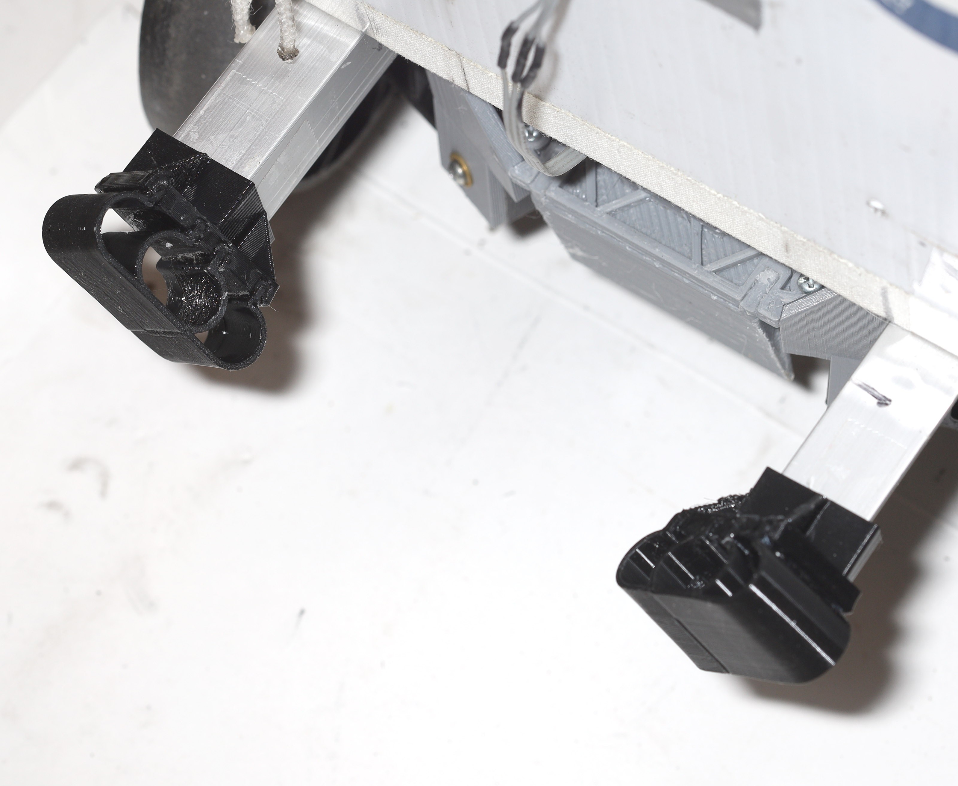
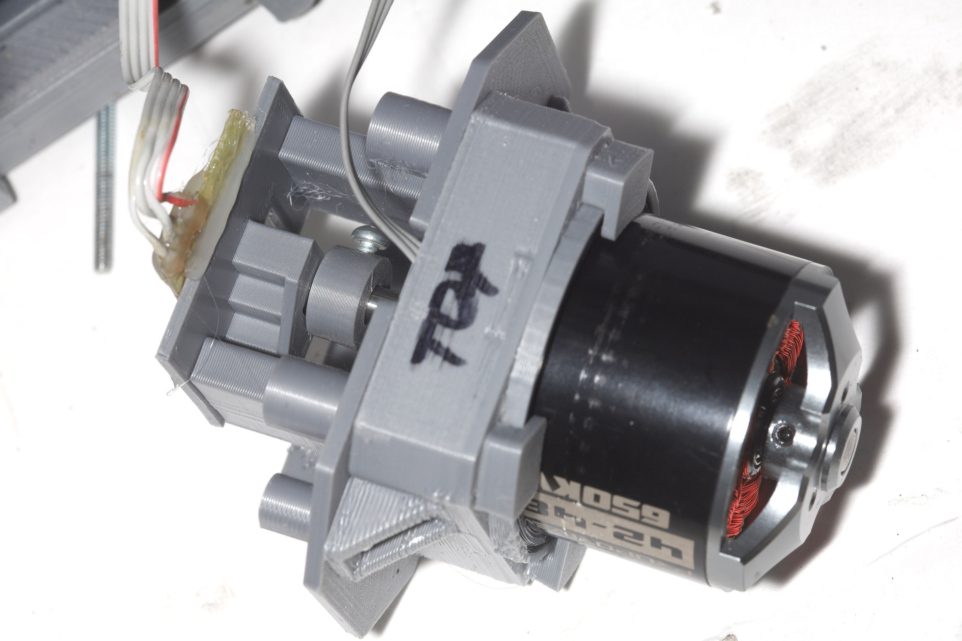
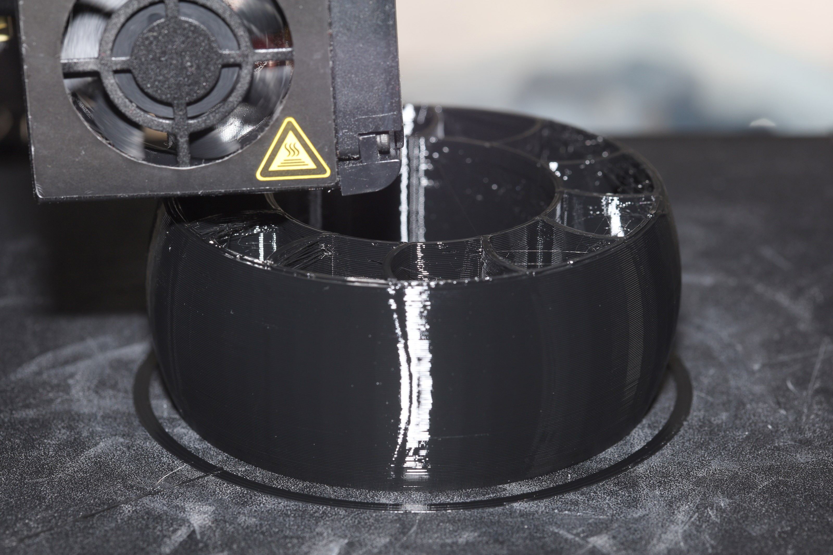
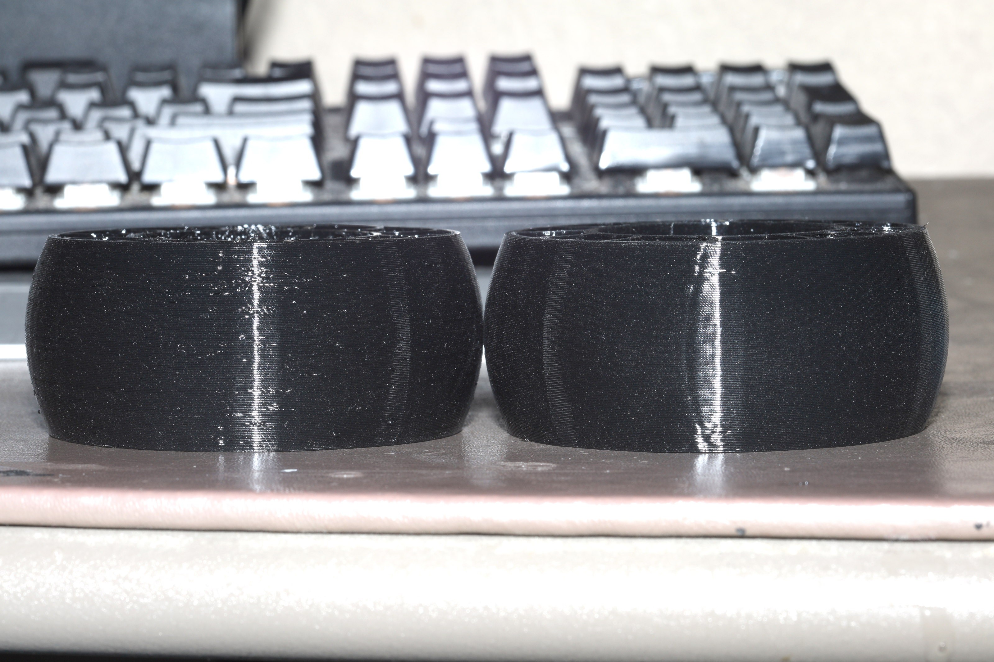
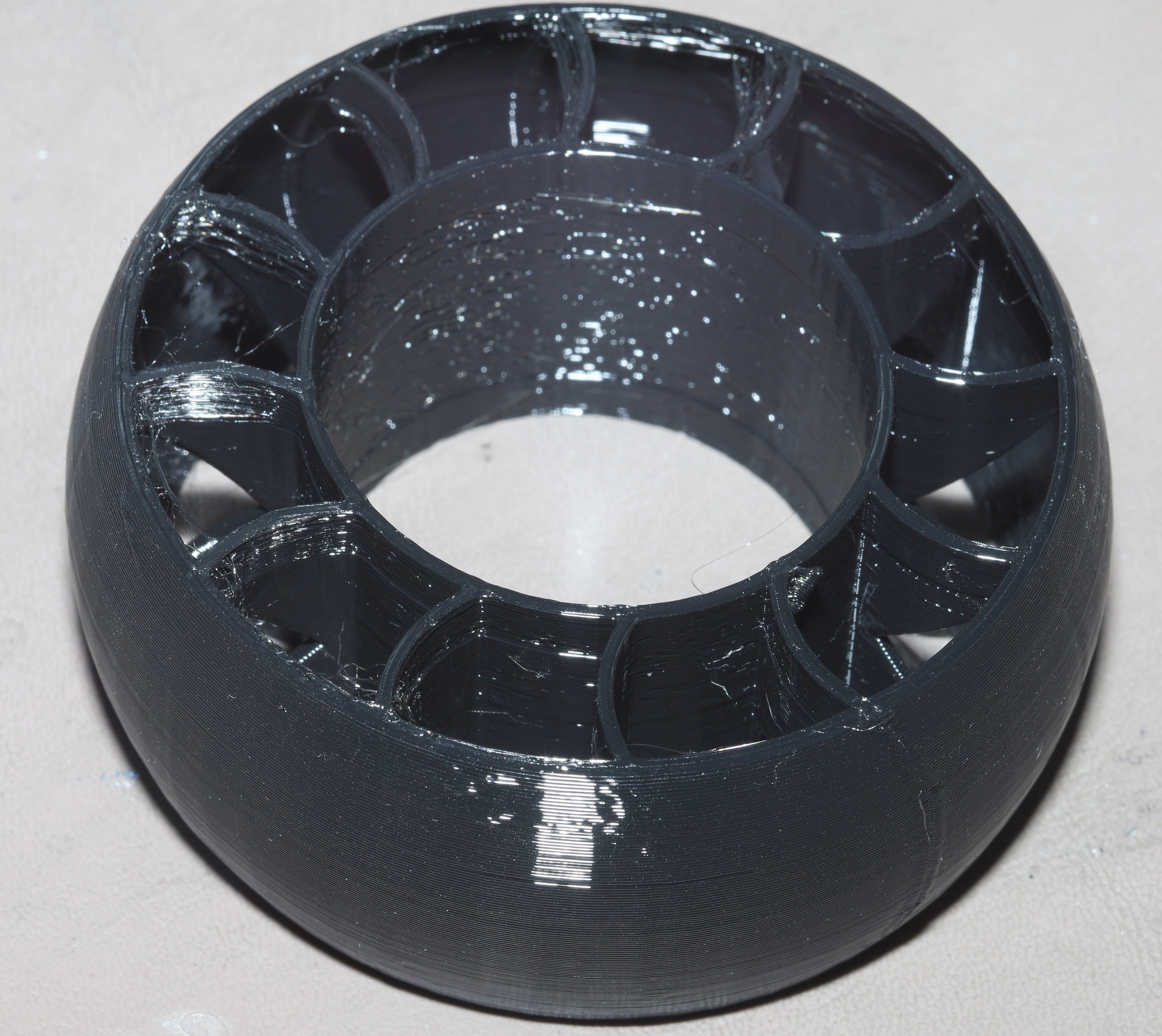
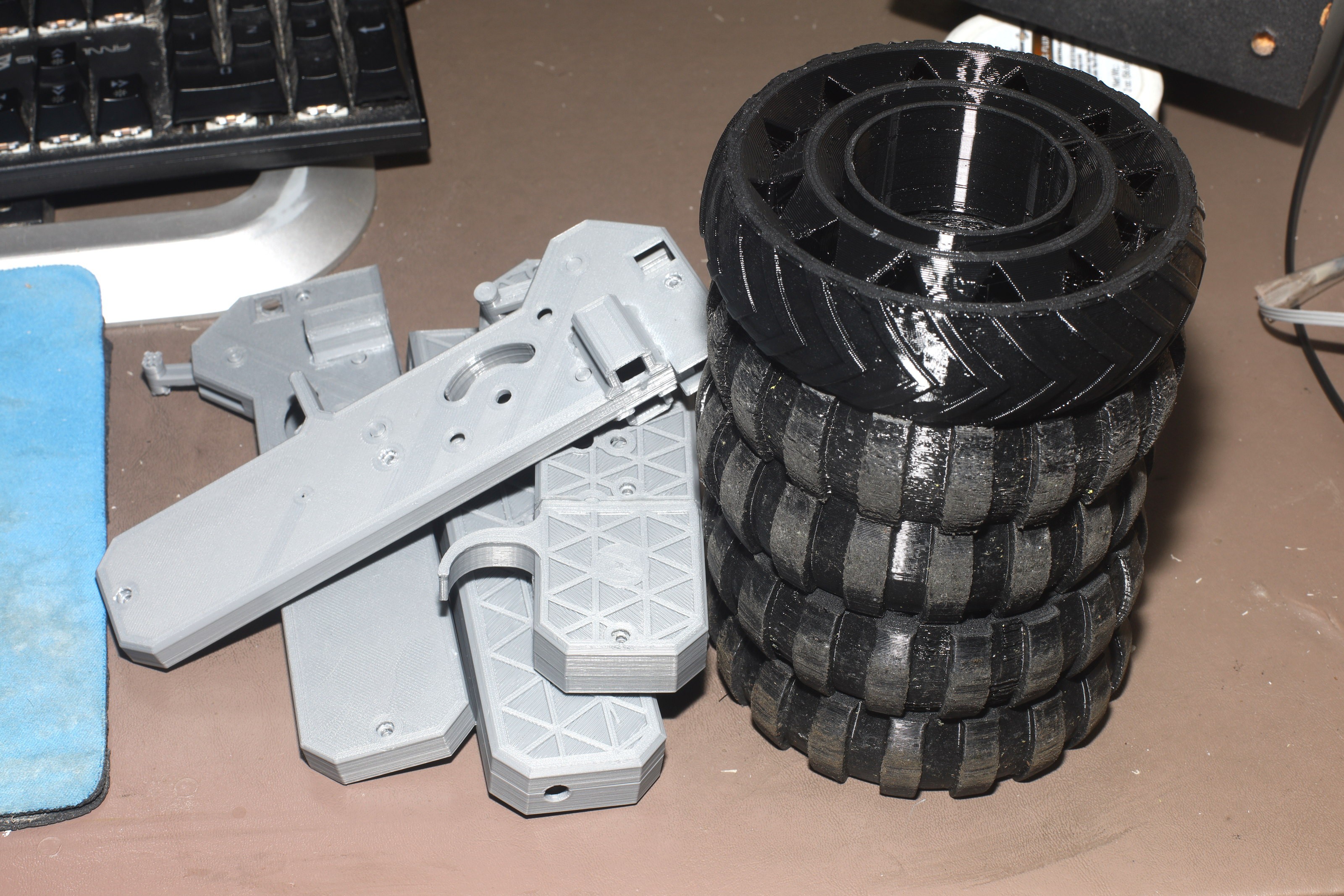
New tire design, heat sinks, motor mounts
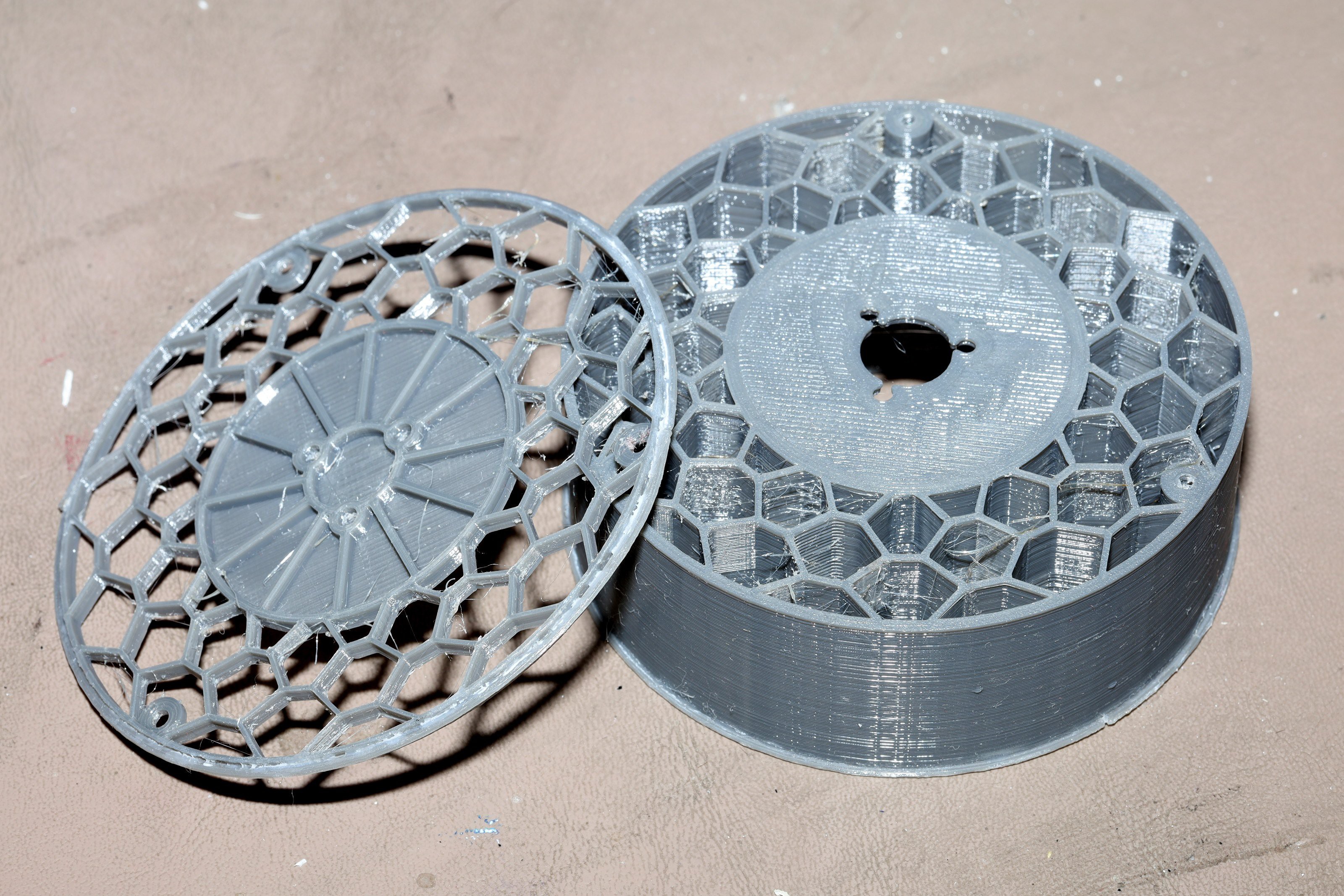
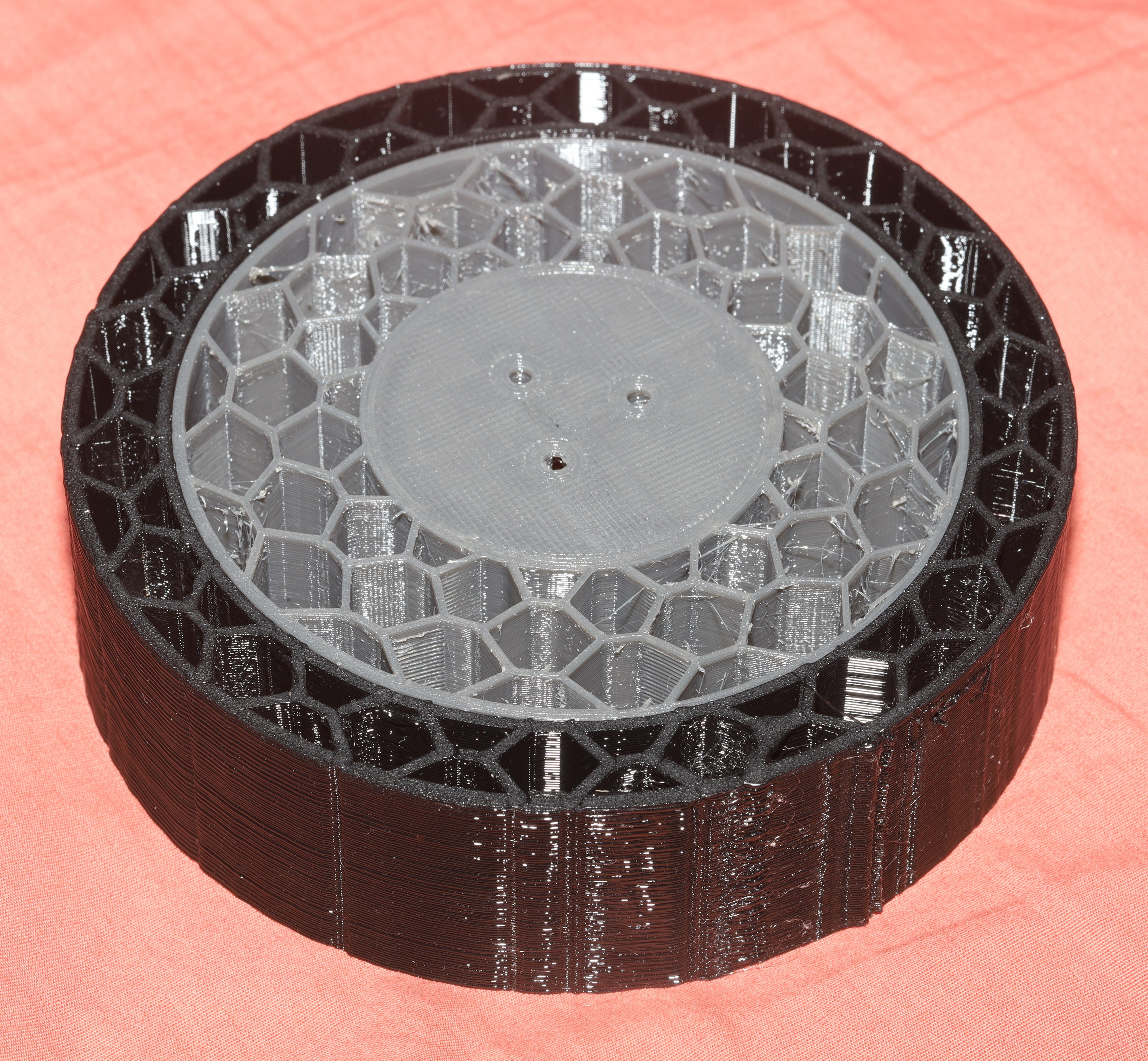
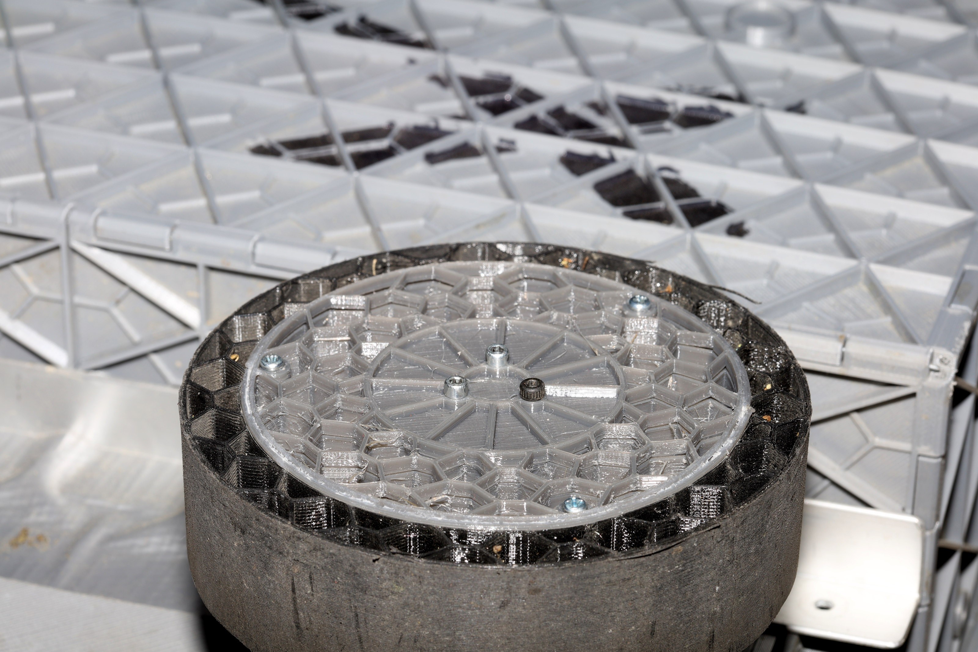
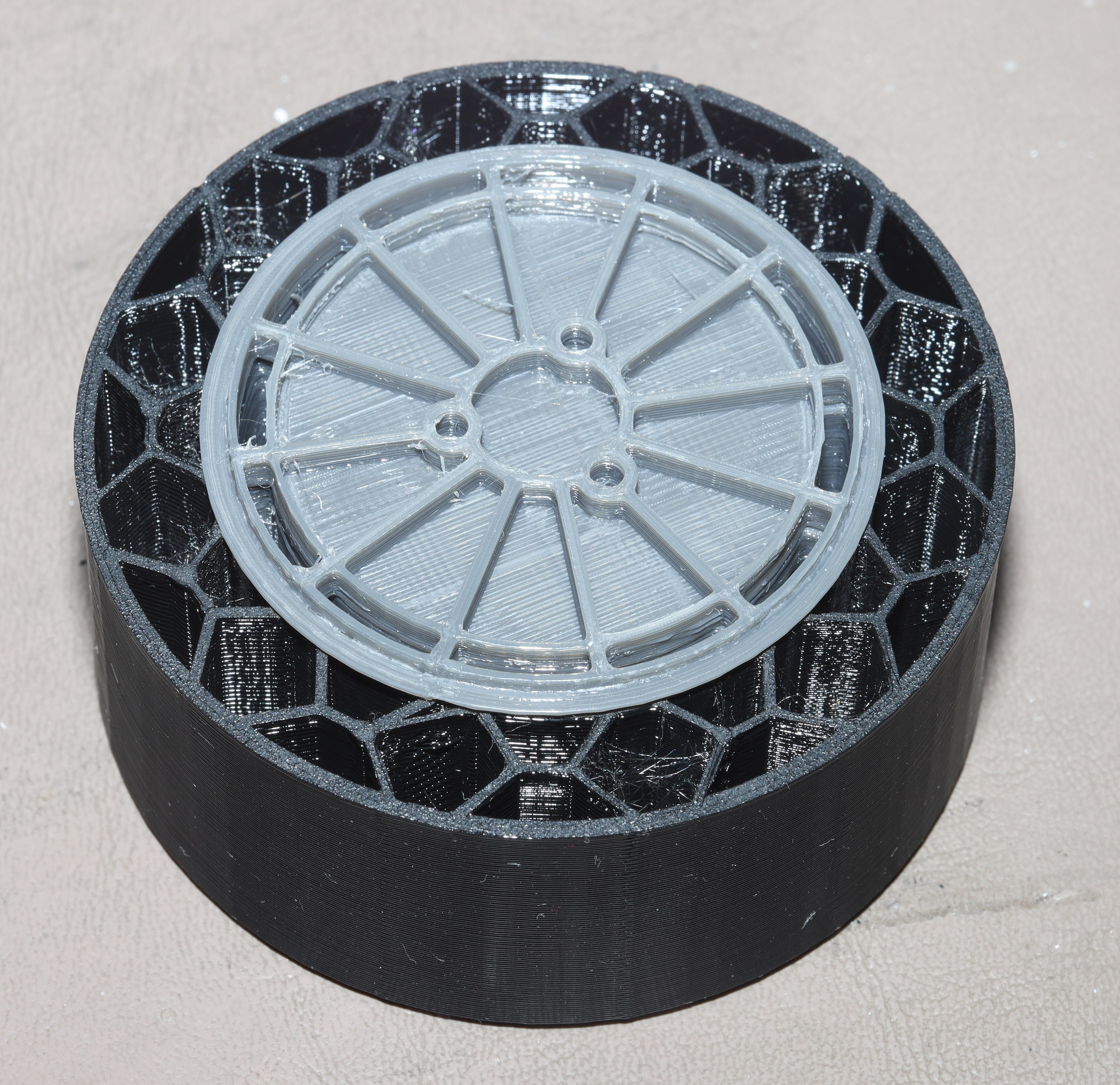
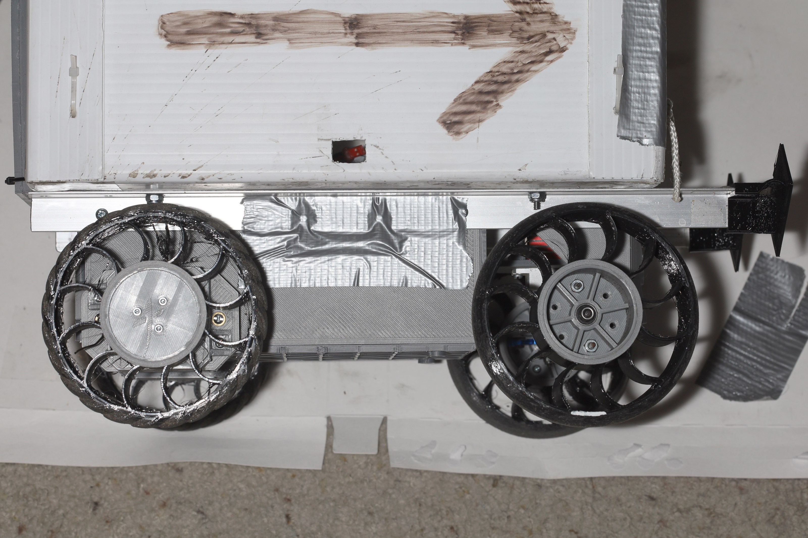
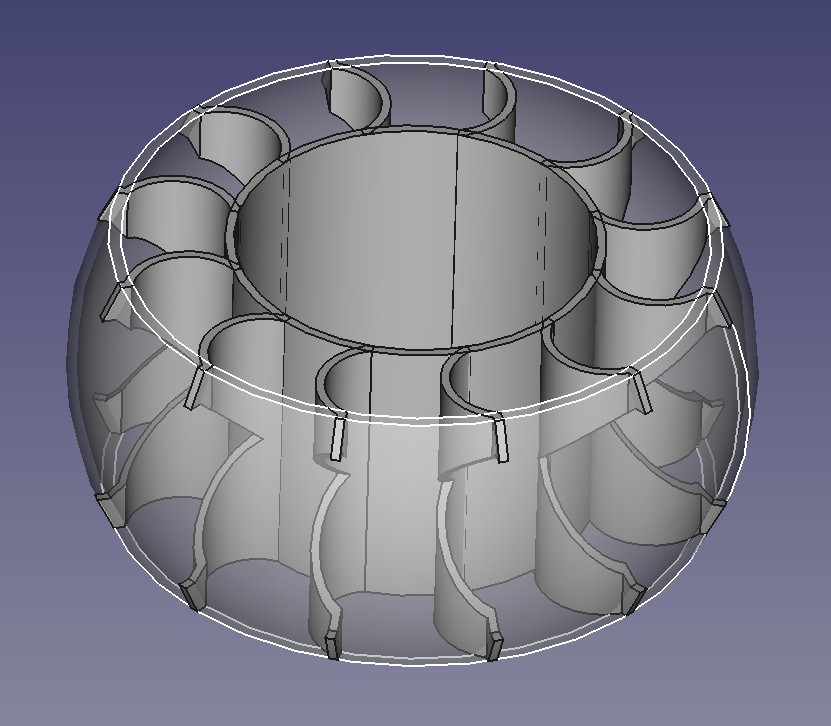
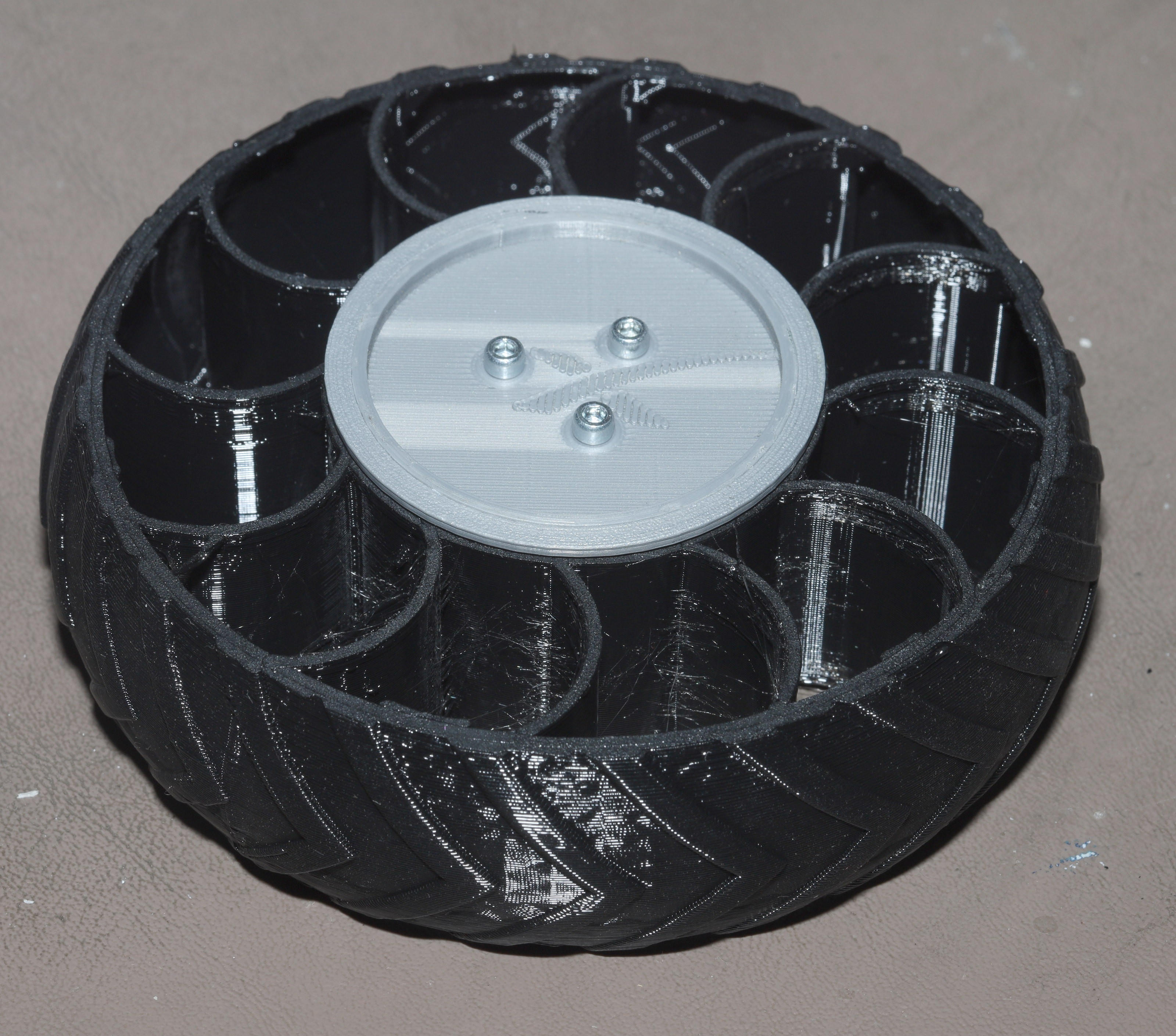
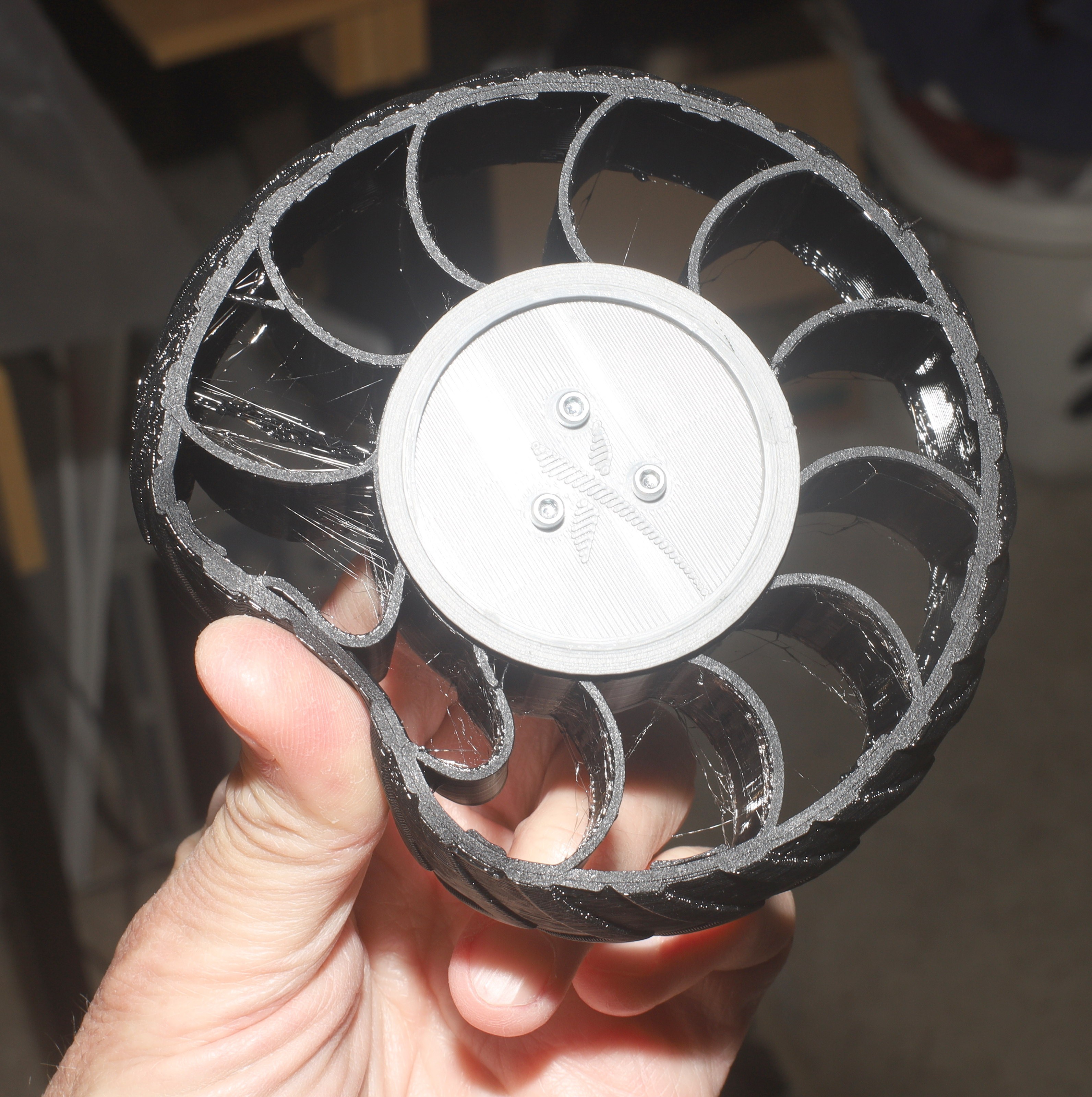
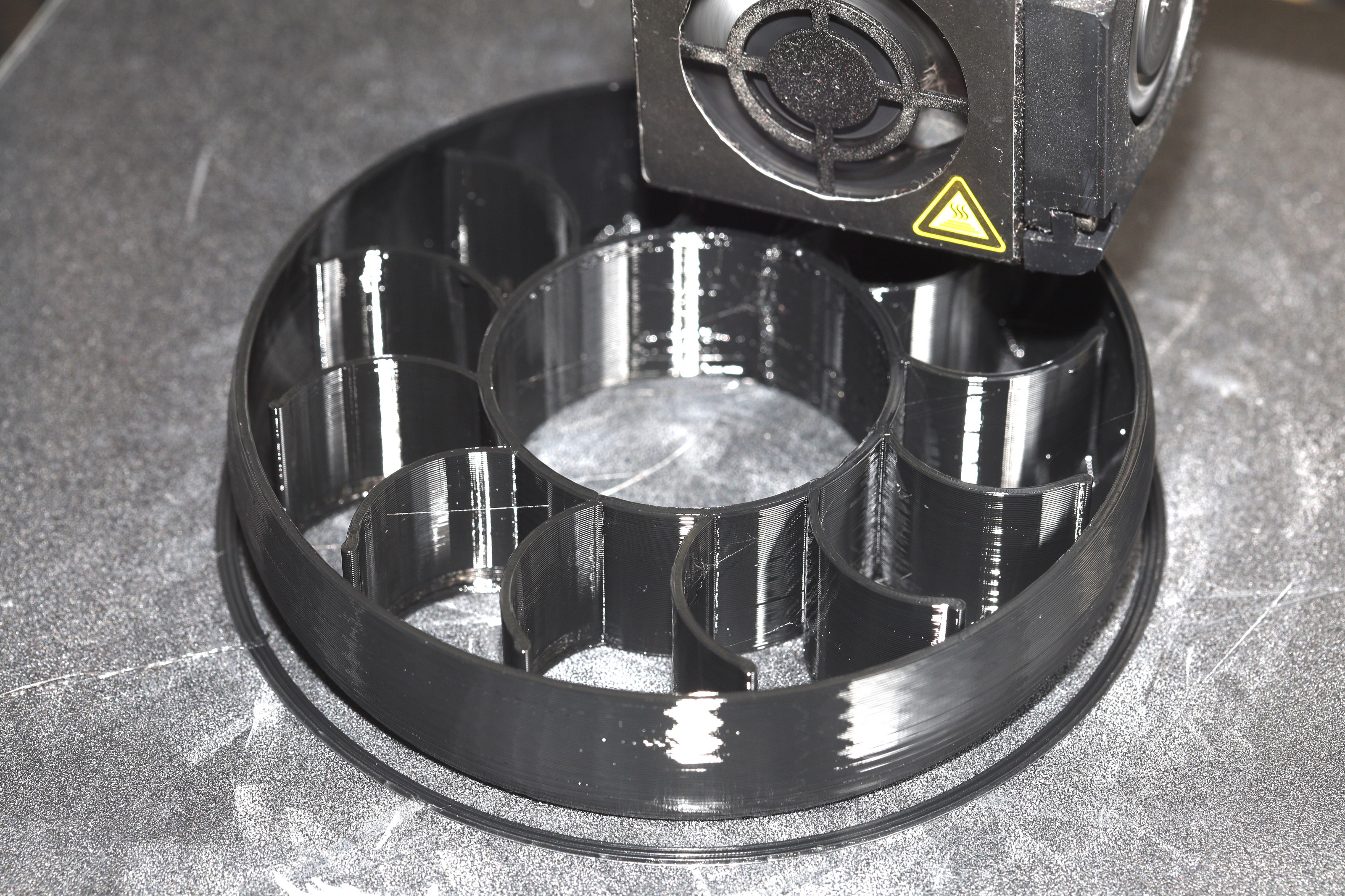
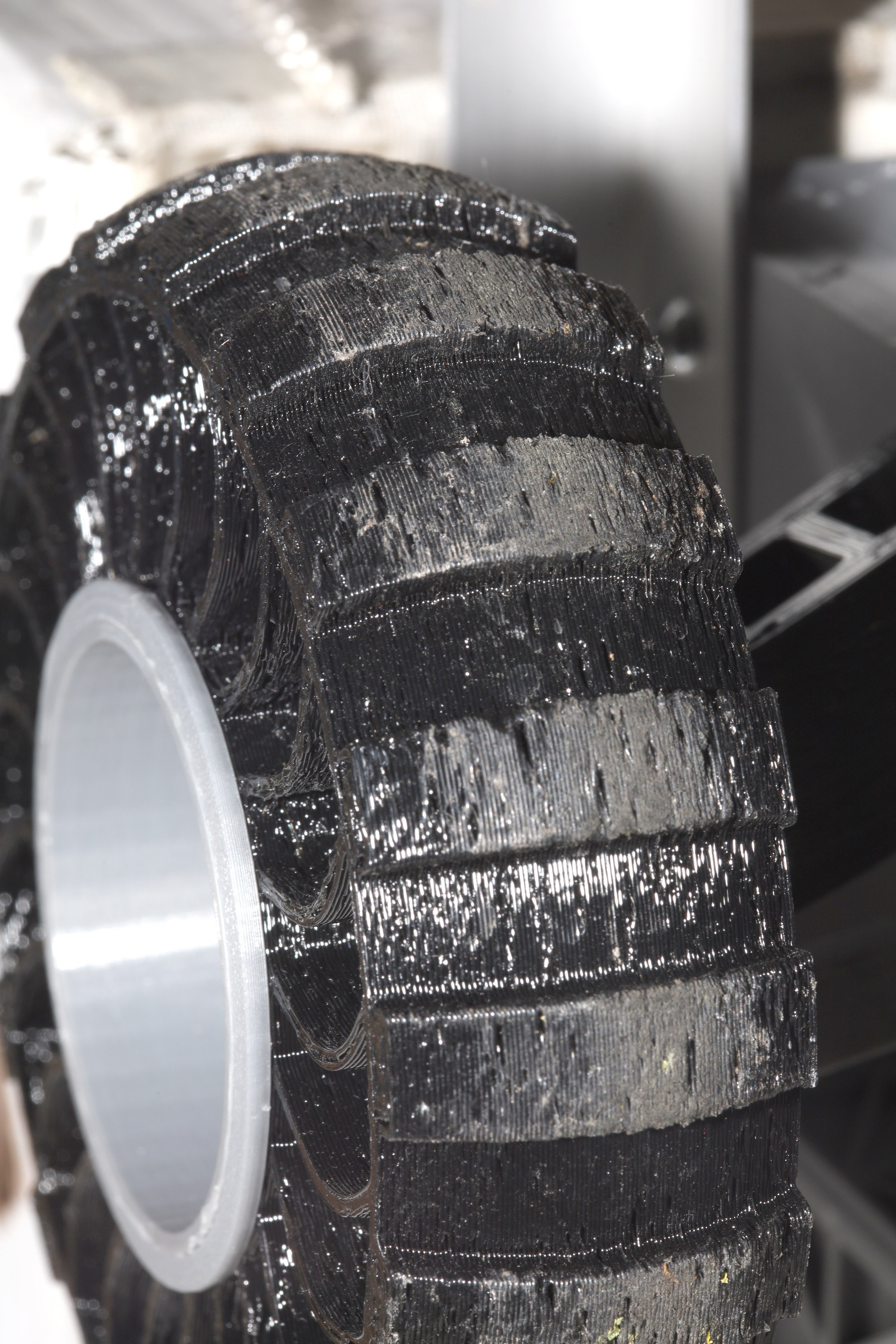
05/21/2021 at 05:39 • 0 commentsPure TPU wheels in the rear proved too soft to do the job. They just sucked amps & hardly went anywhere with a payload. Making them the right hardness without an arch required a much larger hub with thinner tire. The flat tires don't have the structural hardness of an arch, so it all comes from more material. The new hubs would be PETG to handle the heat.
![]()
![]()
![]()
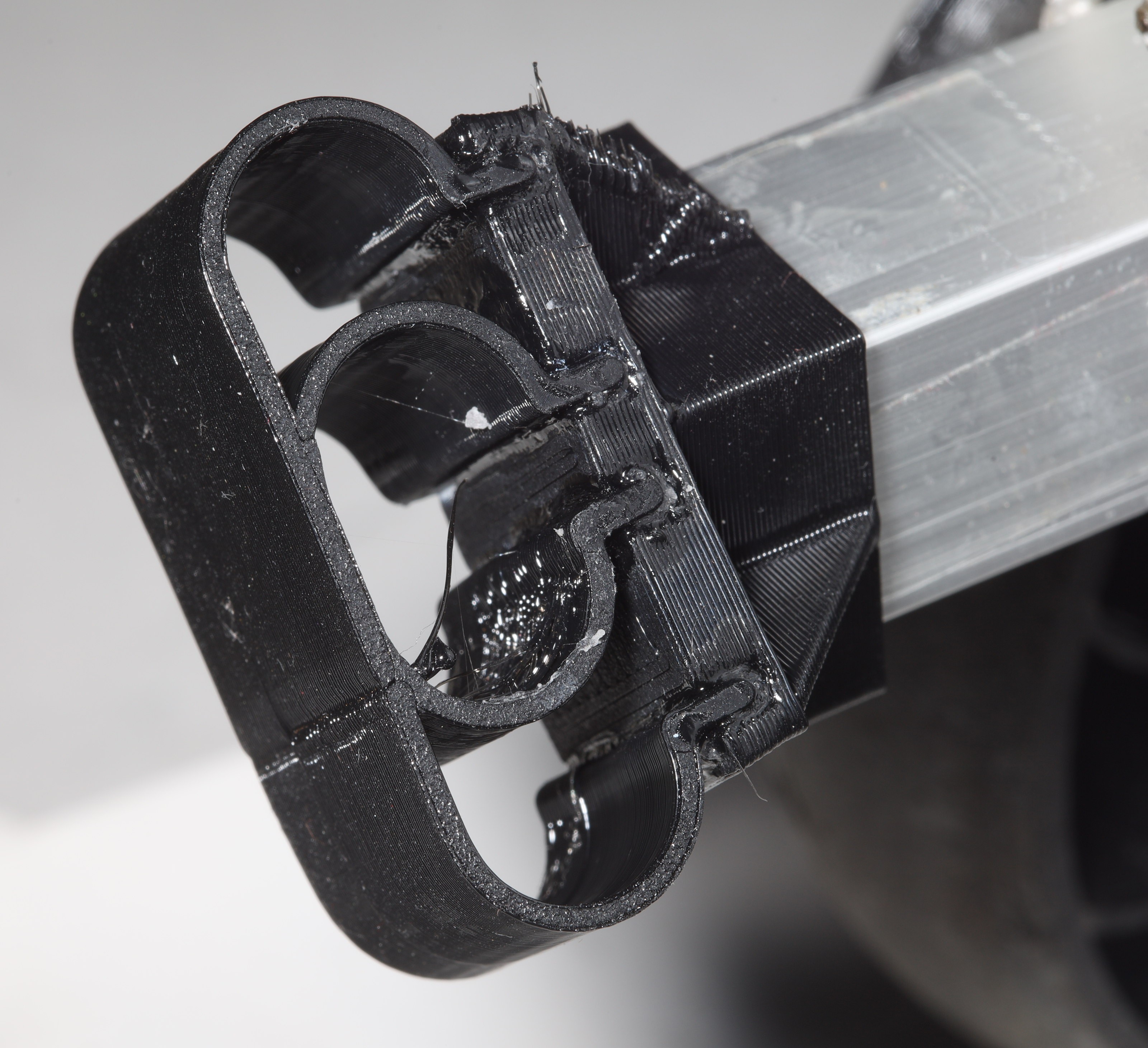
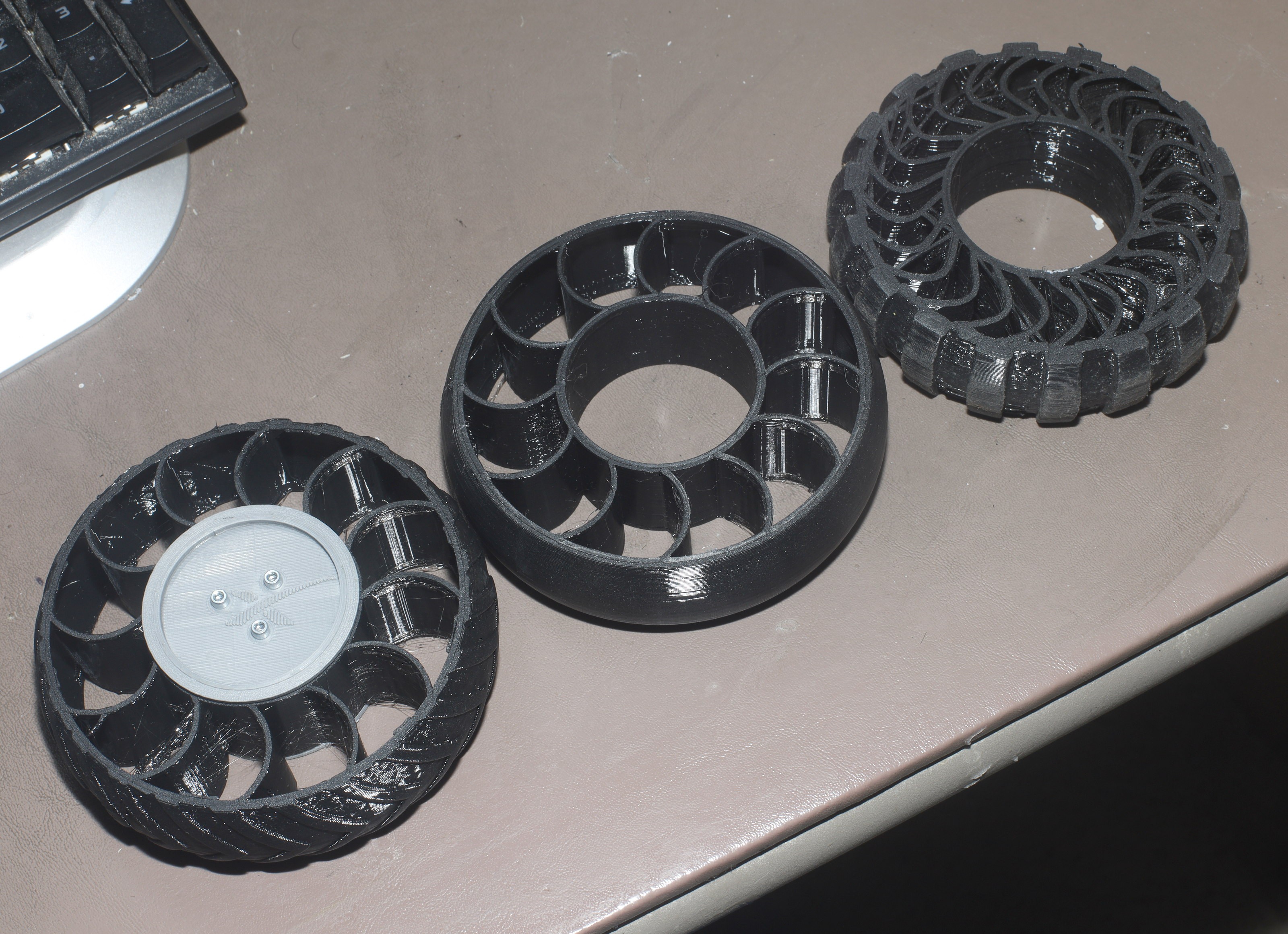
The mane problem with a large hub is keeping the tire in place, since the tire just slides out & pushes such a large clamshell aside. After a few failed farsteners, the best solution was to rubber cement the tire on. Rubber cement secures it enough, the hub may end up 1 piece.
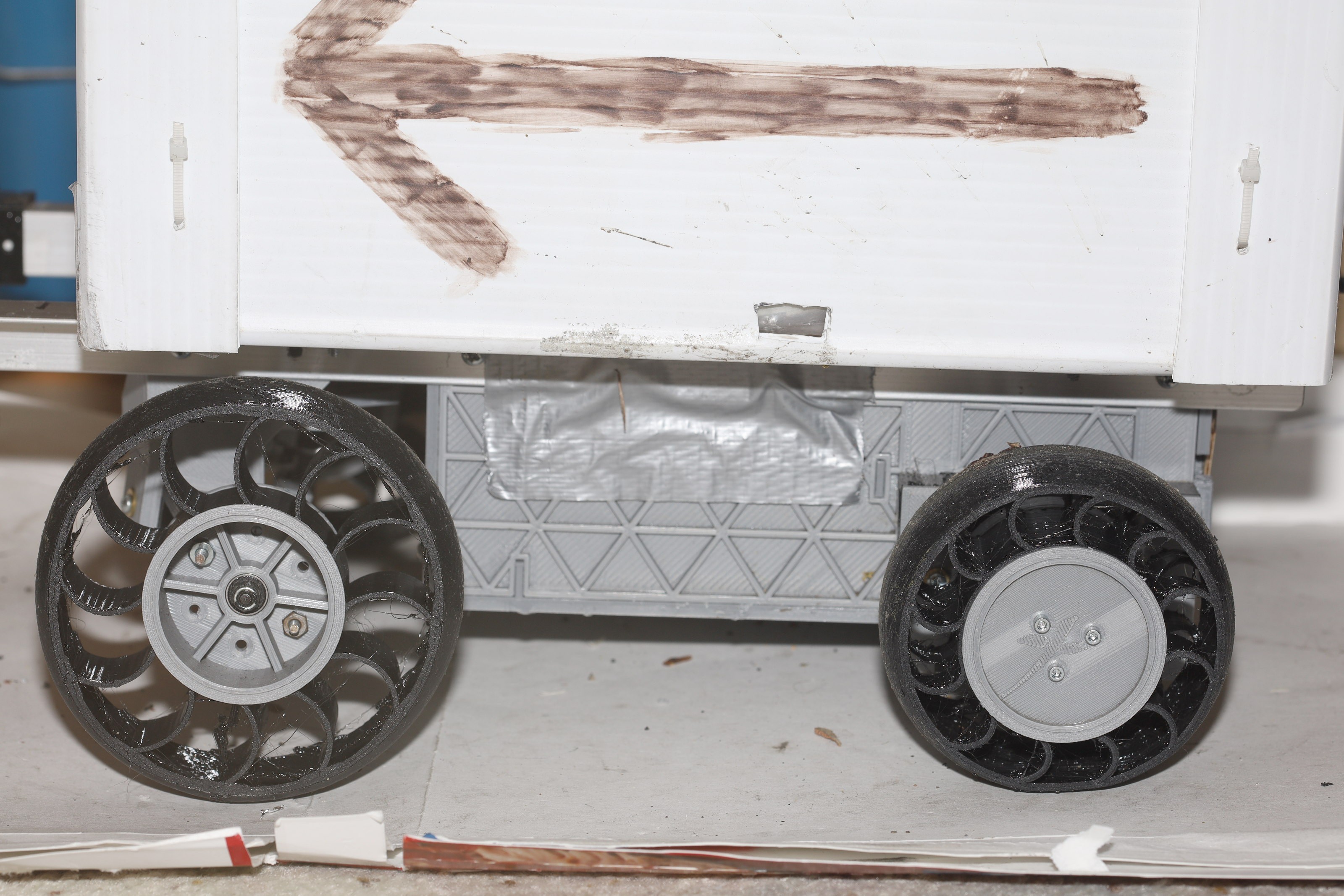
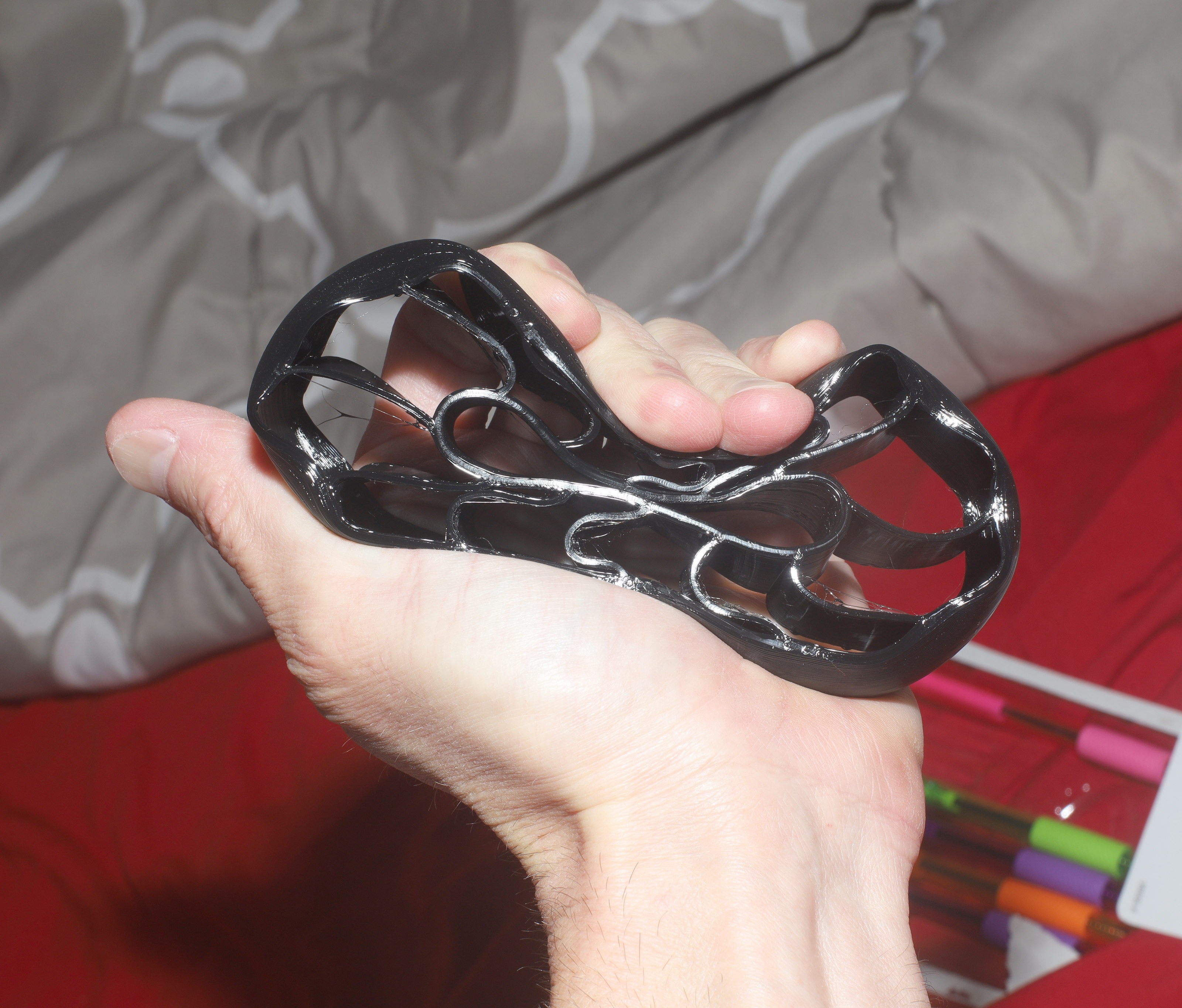
Warmer weather was causing the motors to overheat a lot more, so there was a keen interest in increasing motor torque. Getting enough torque for such large wheels proved difficult, so there was an attempt to make the smallest possible wheels. The smallest wheels before bottoming out were 74mm.
![]()
![]()
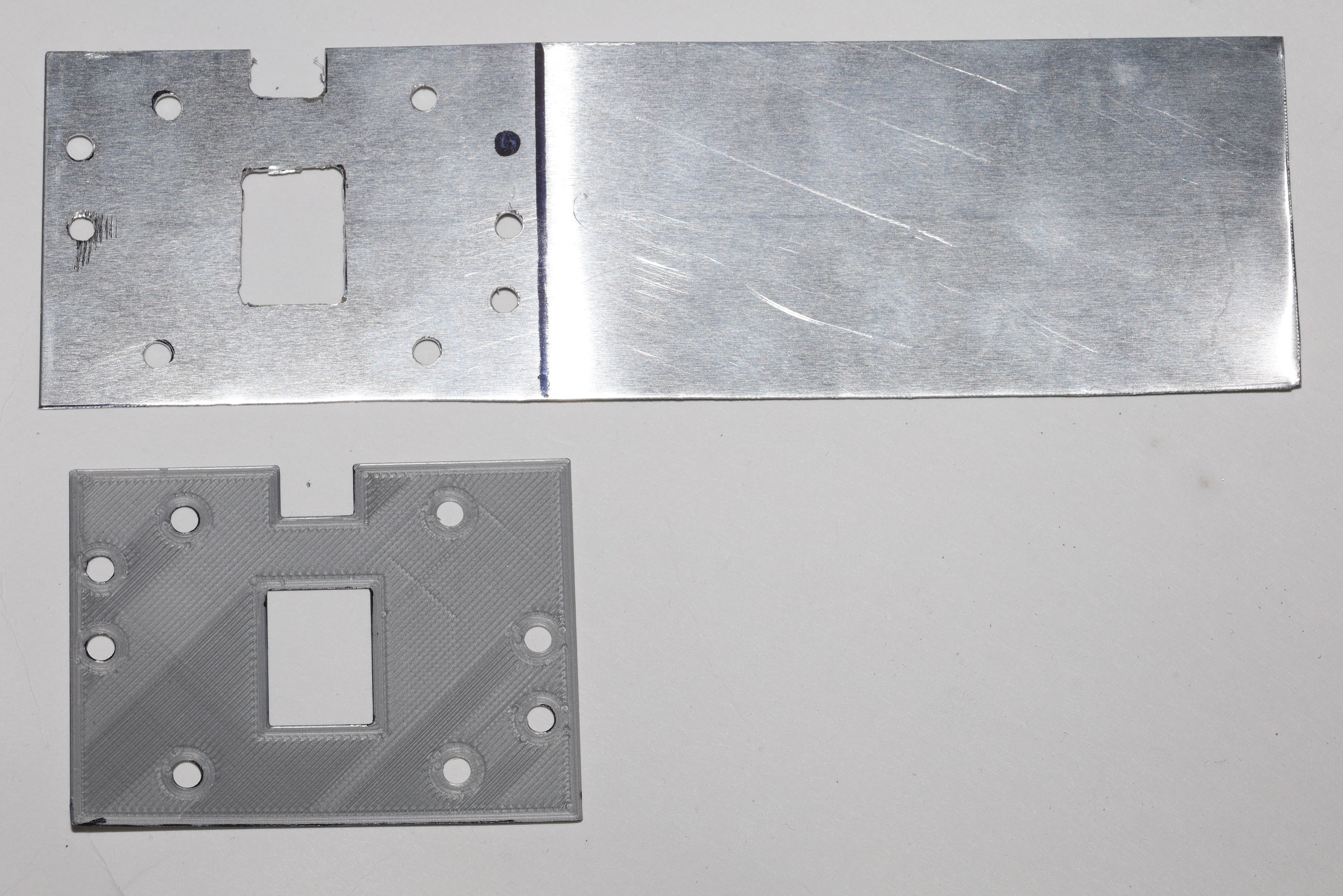
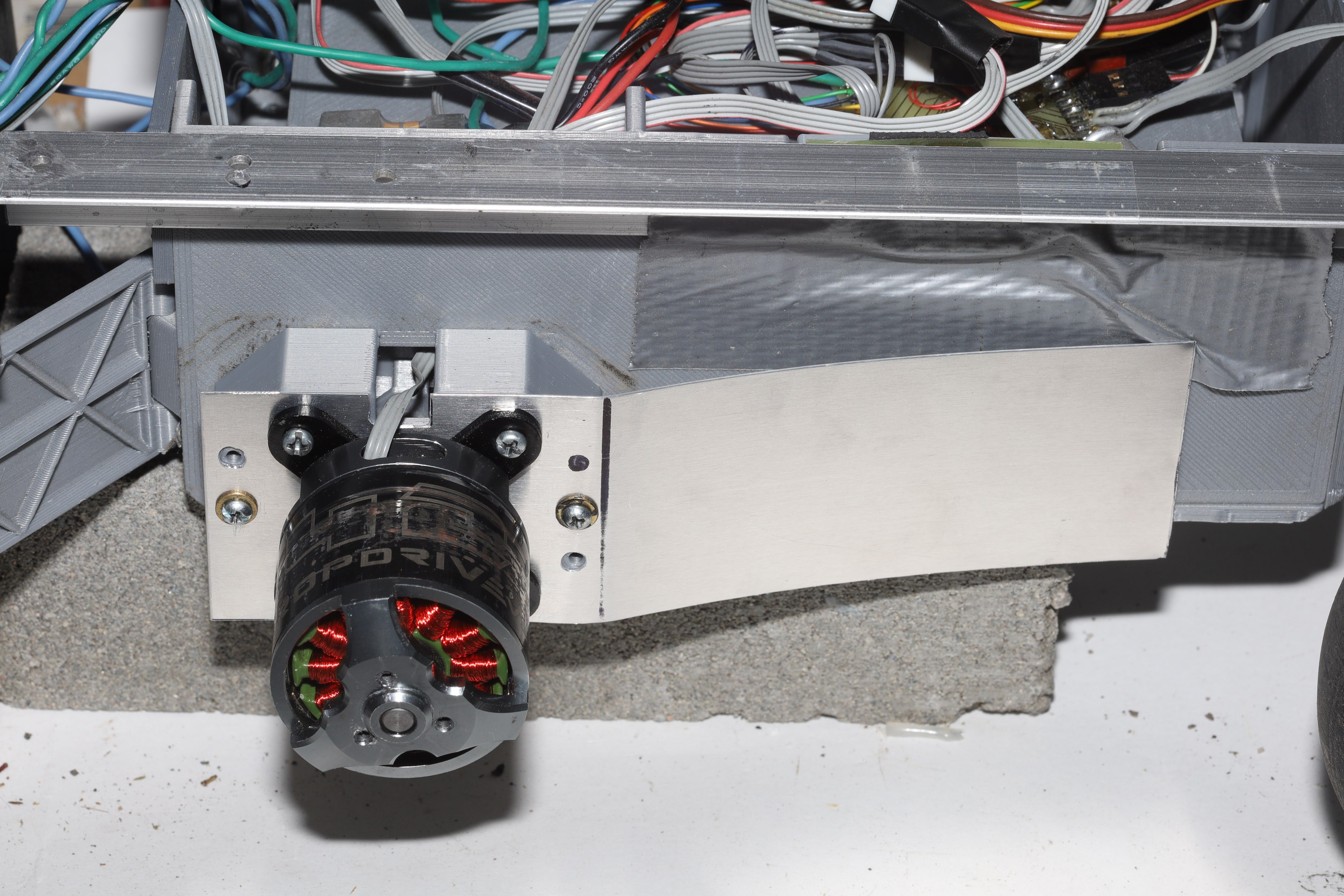
Helas, this proved too low for the terrain, so back to 108mm it was. The next step was starting to passively cool the motors with heat sinks.
![]()
![]()
![]()
The only aluminum outside China was 1/32" thick. The trick is the only way to test the heat sink is overheating the non heat sinked motor.
The next problem is the motor mounts were converted to pure PLA instead of part TPU to try to simplify fabrication. This caused the farsteners to come loose more easily. It seems having part TPU motor mounts either created a self locking tension on the nuts or dampened vibration.
The way the motor mounts farsten to the chassis has always been ugly. The farsteners are hard to reach. They tend to loosen on their own. It may be the farsteners just have to be bigger, but another idea is creating an all new chassis with motor mounts that attach to the angle rod. It would just require gluing more parts & that requires a lot more infill.
-
Remote, motor, steering, tire upgrades
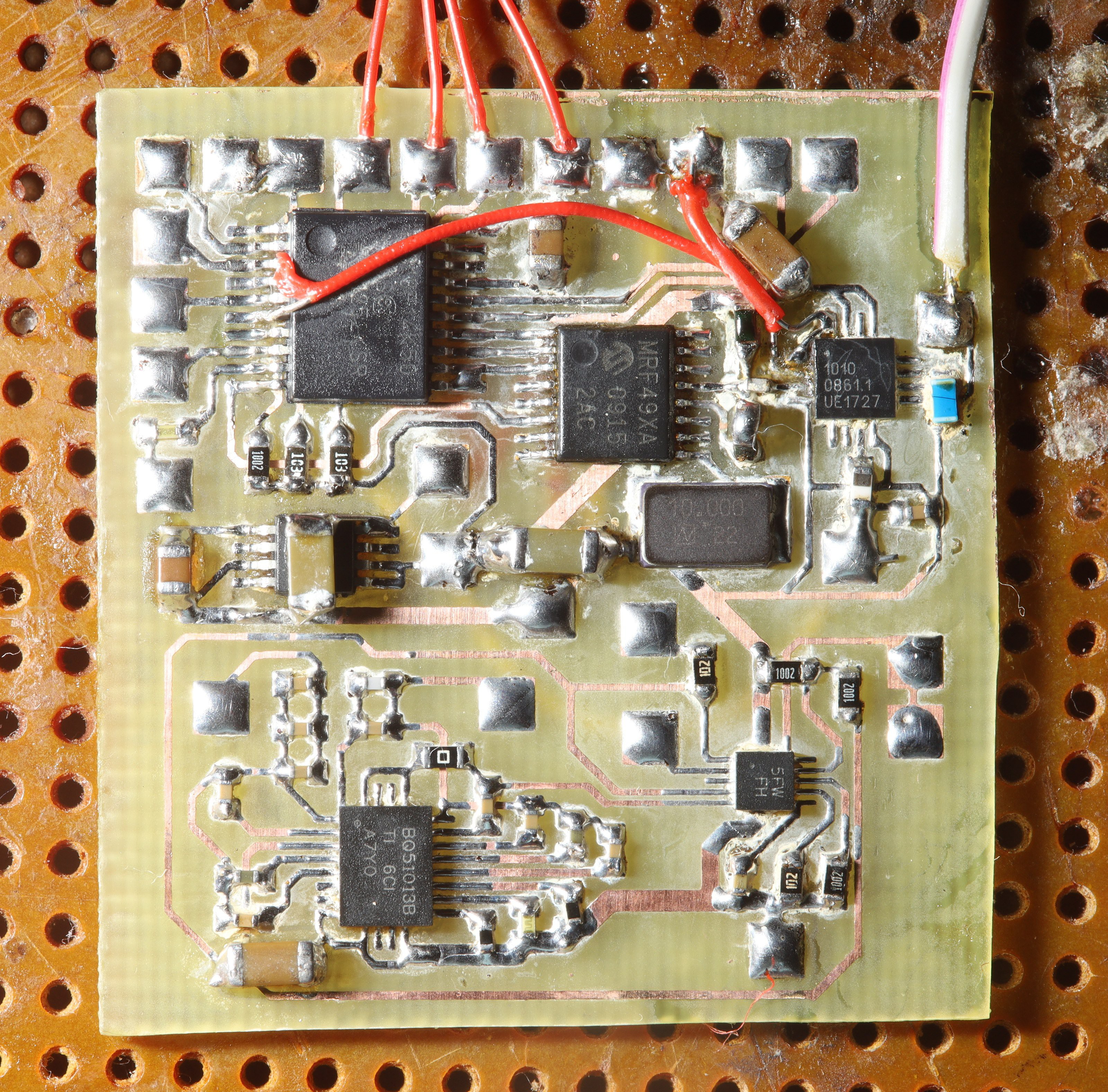
04/08/2021 at 06:35 • 0 commentsThe truck had lots of radio dropouts, especially near phone towers where GSM overlaps the ISM bands. After 12 years of using very low power 5mW ISM radios, the decision was made to finally whack in a 500mW amplifier, the mighty RFX1010. It's very simple to hook up compared to the more powerful SE2435. The lion kingdom's 1st home made transmitter above 5mW finally lived.
The trick with the RFX1010 is the antenna input is shorted to ground at DC. It needs a 33pF blocking capacitor. Then, when the transmit enable pin is on, it burns over 150mA with no input. When the transmit enable pin is off, it burns nothing. This pin needs to be actively turned off when not transmitting. Receive enable & mode have to be grounded to get it to completely shut down. The control pins are floating. Mercifully, the switching time is only 1us.
It consumes so much more power than the MRF49XA, a big cap was required on the input of the voltage regulator & the micro needed a startup delay.
![]()
![]()
![]()
![]()
![]()
The duty cycle was low enough to use full 500mW without killing the battery. The mane problem with this is it seems to saturate the receiver & interfere with the camera controller. It may have to be reduced. That is believed to involve reducing the output of the MRF49XA, the same as using a fixed audio amplifier. The most powerful commercial radio lions had was the 50mW XBee PRO 900 & it never had any problems for ground vehicles.
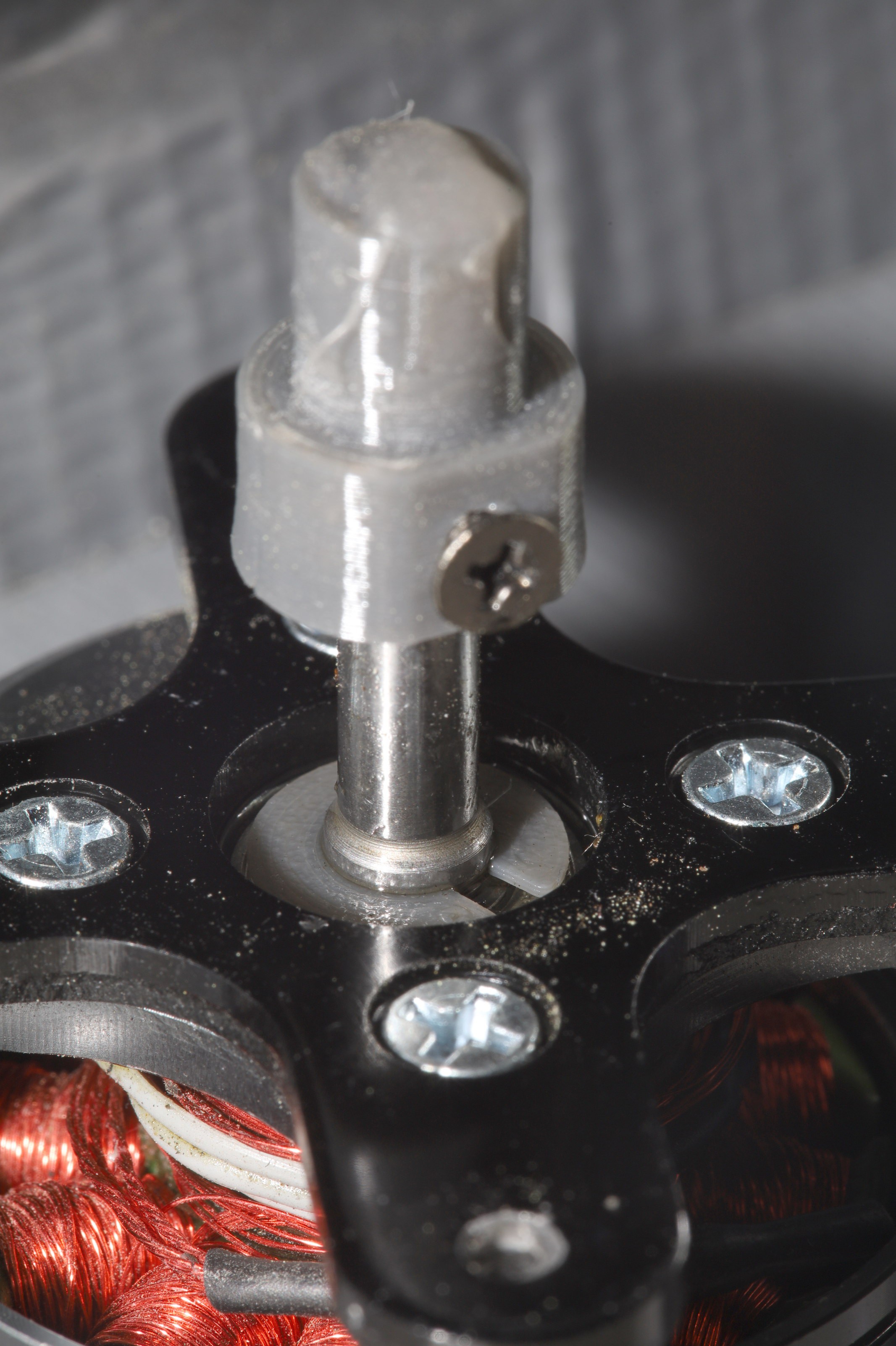
There was a bought of motor seizing which was believed to be the tolerances of the motor shroud being too close while warmer weather made the motor expand more than it used to. The only option was just scraping away material & hoping for the best. Even this zealous shroud didn't keep all the rocks out of the motor.
![]()
![]()
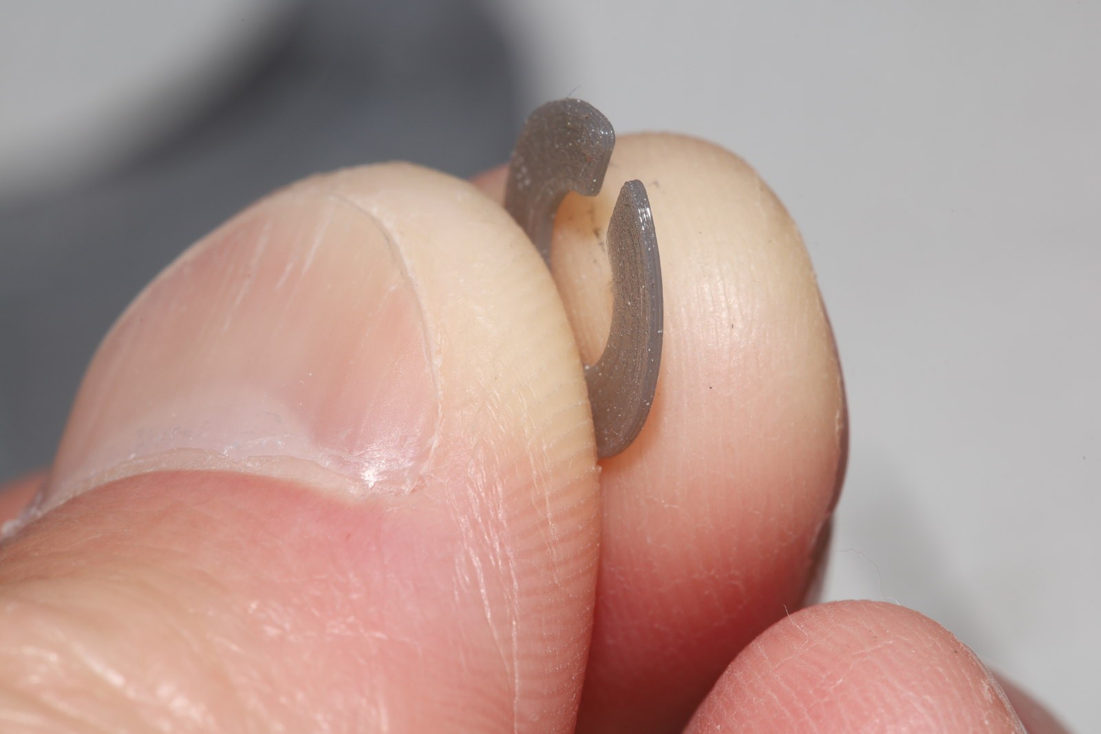
The o rings were quite chewed up from either rocks or the wheel slipping out of its bearing & being forced back in. The wheels were slipping out of their bearings a lot more, so it was time for the lion kingdom's 1st 3D printed retaining rings.
![]()
![]()
Out of PETG to handle the heat. .6mm thick was enough to offer good retention of the wheels, but never as good as the original metal rings. Thus ended a 20 year history of needing replacement retaining rings for various motors, but never having a way to fabricate even a minimal replacement.
That was followed by another attempt to prevent the steering from glitching. It was believed to be glitching because of I2C errors. 10 years ago, I2C on the STM32 was assumed to be vulnerable to electrical glitches. Lions resorted to limiting I2C to 150khz & shielding the I2C cables, which worked most of the time. In the last 5 years, the internet started to lean towards a hardware bug involving concurrent register writes & recommended bit banging all I2C.
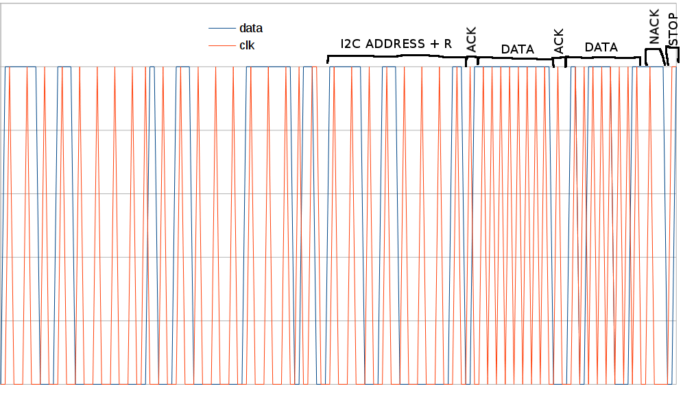
The lion kingdom always had a bit banging I2C driver, but burst mode never worked & bit banging is too slow without burst mode. Revisiting the driver 10 years later involved printing the pin values in software rather than soldering on test points. Then, comparing the bit bang waveform to the hardware waveform finally revealed the problems.
![]()
The invensense IMU's require a stop code to update their measurement registers, otherwise the measurement registers always contain 0. The stop code needed the clock to rise a nonzero time before the data.
For burst mode to work, the data needed to rise a nonzero amount of time before the 1st clock of the data byte. If the data didn't rise before the clock, the entire byte would be 255 or only numbers below 128.
What makes I2C such a difficult protocol is the unusual timing orders & data types. Sometimes SDA needs to change after SCL & sometimes before. Sometimes SDA needs to be written before it can be read. Sometimes it uses a byte & sometimes a single bit code. The lion driver is a case of overzealous code reuse at the expense of readability. It would be easier if it copied the same routines everywhere instead of using a complicated heirarchy of state variables.
Bit banging with burst mode allowed the gyro to be read at 430Hz without any glitches so far. It pleased us lions to be able to fix a problem 10 years after giving up on it, simply through increased skills.
The steering still glitches, but now it seems to be continued radio problems or servo related. At least it glitches less than it did before.
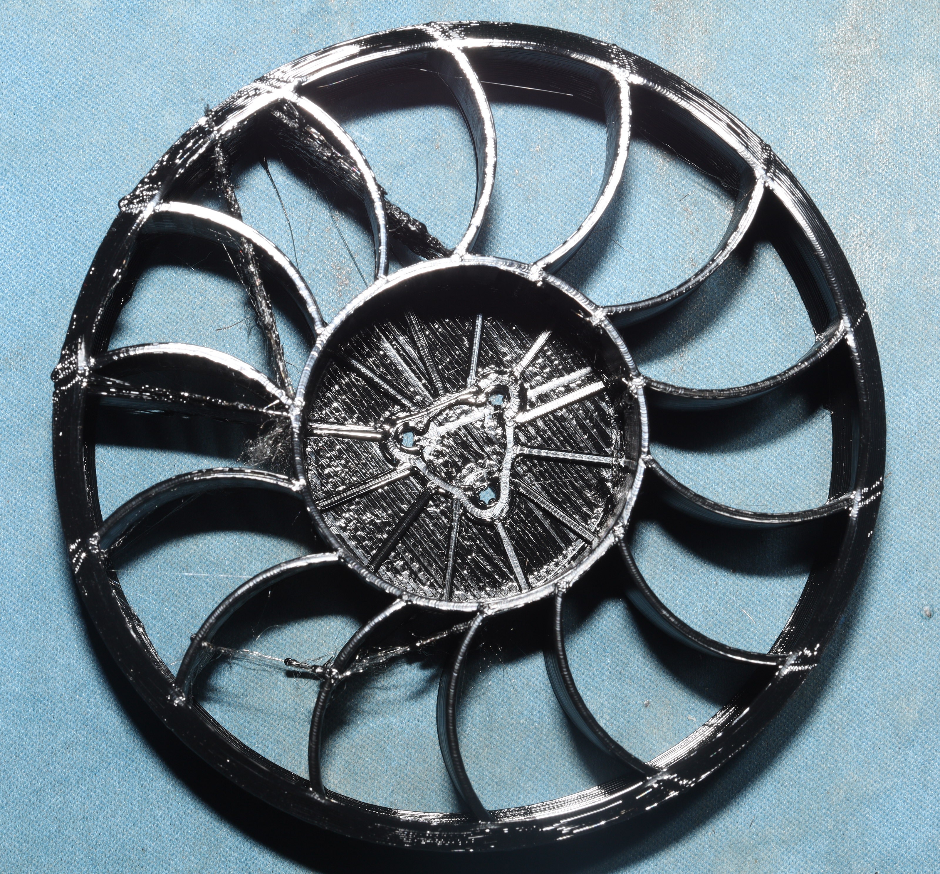
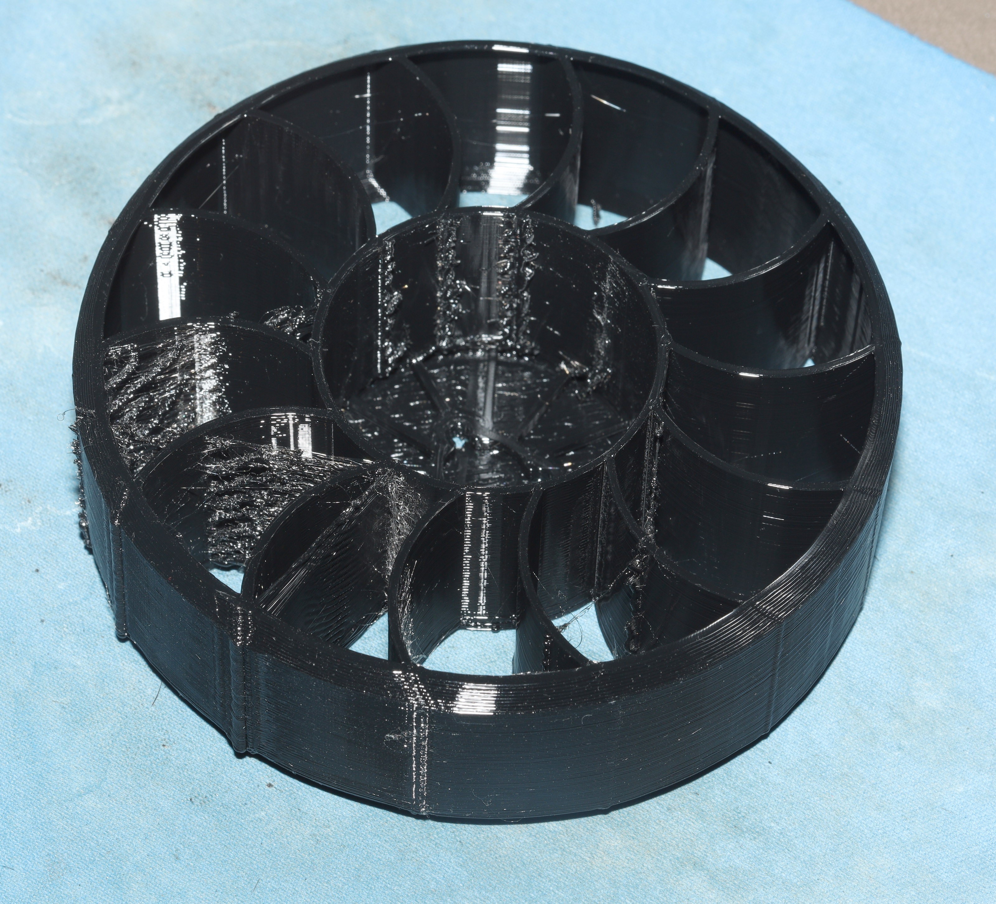
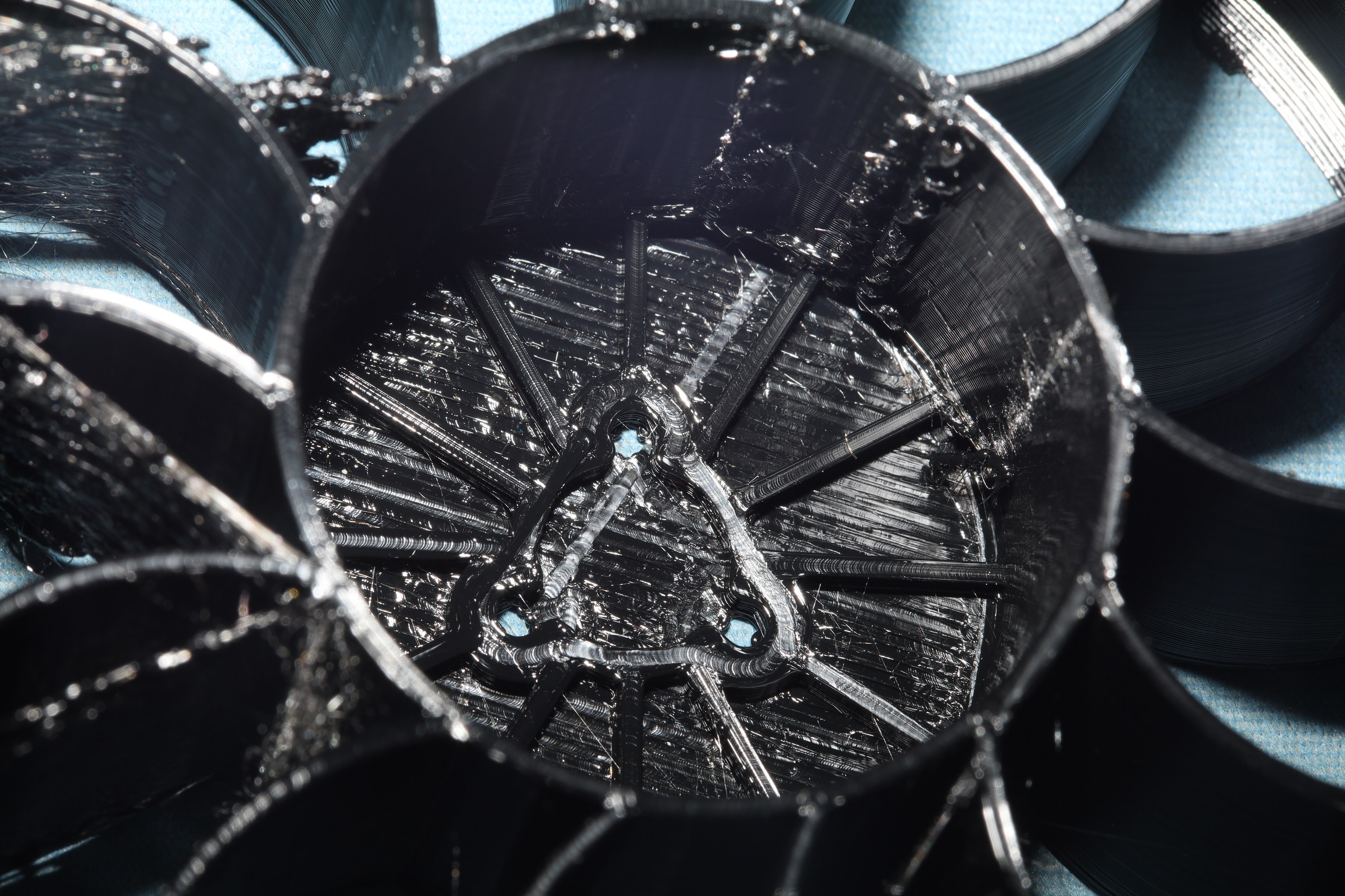
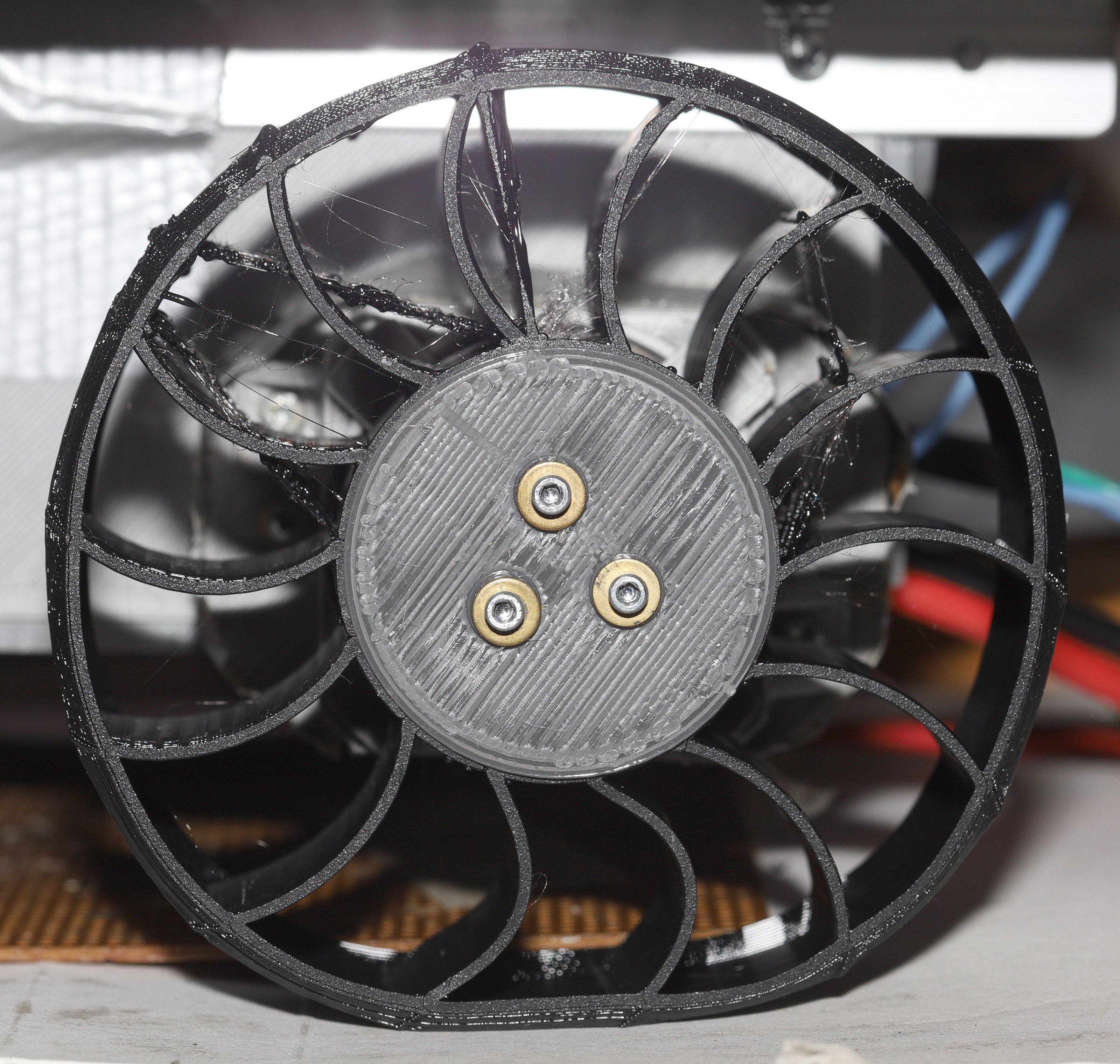
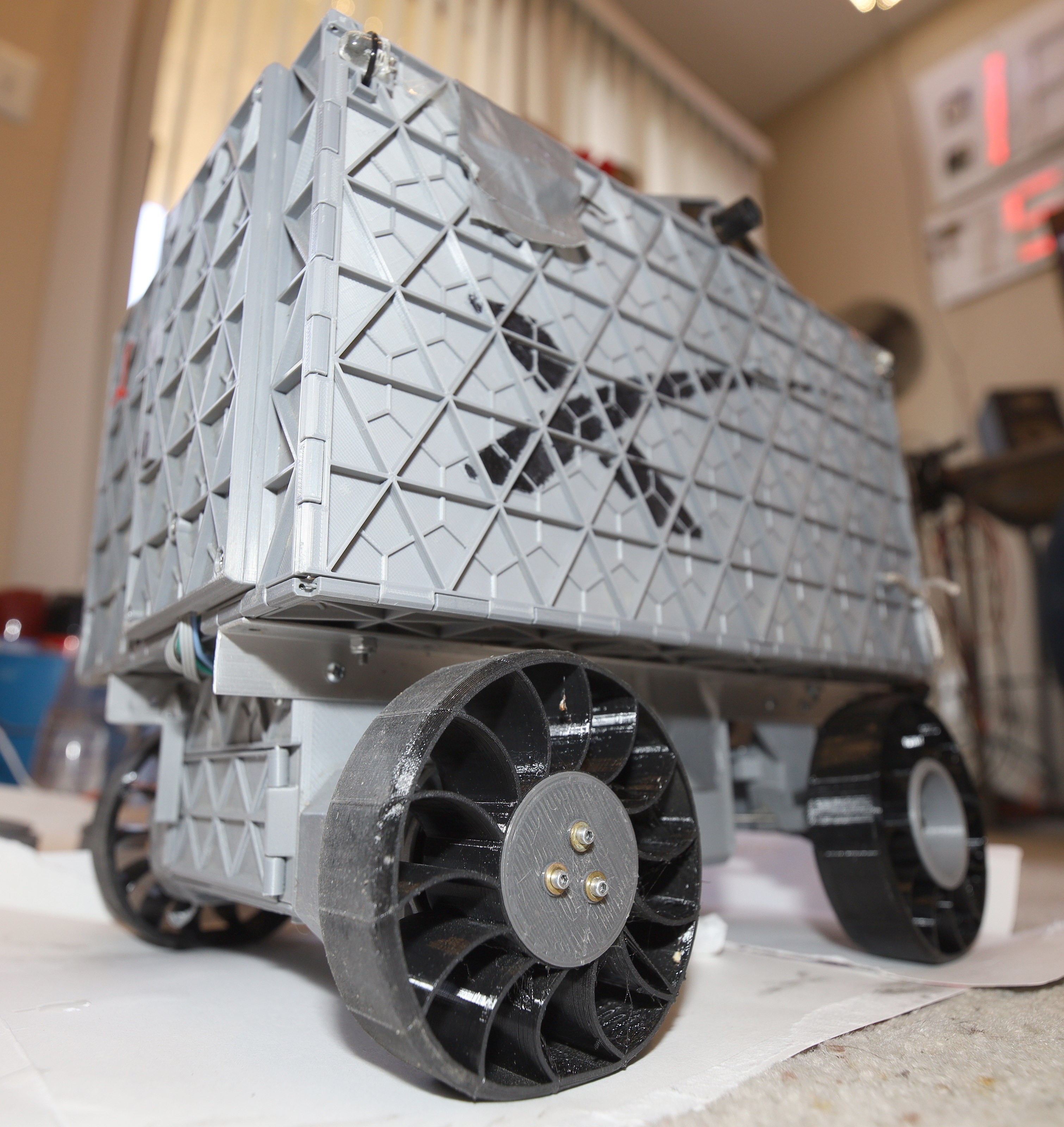
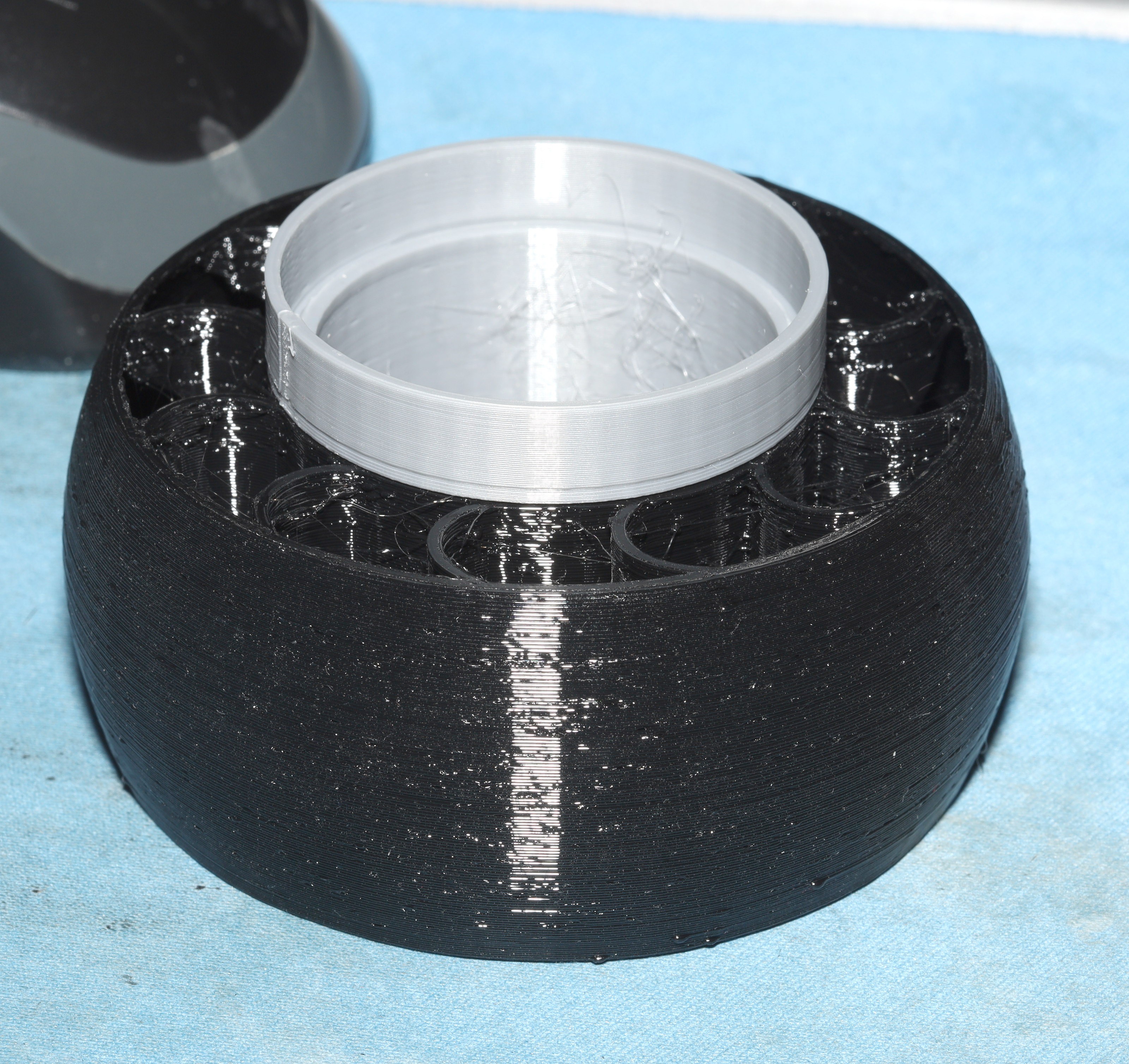
The high temperatures created by the motor seizing up ended up melting the PLA parts of the wheels. The cost of the TPU & the amount of material in the modern tire design has been reduced enough to make a single piece tire wheel with no PLA possible.
![]()
![]()
![]()
![]()
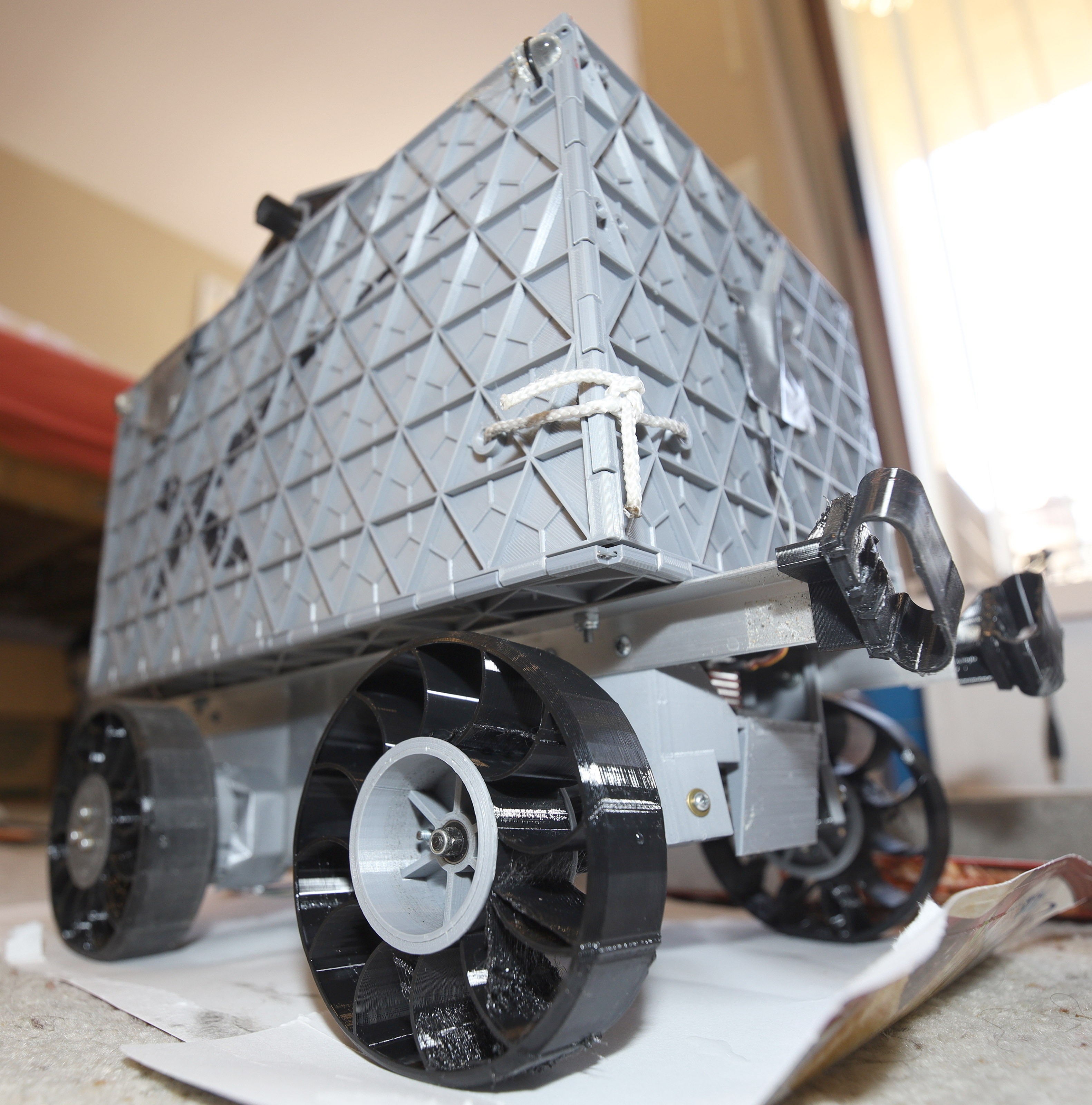
Behold the 1st tire which bolts directly to the motor, stringing & all. The stringing was actually better if timelapse mode was enabled. It ended up needing a hub cap to keep the bolts from punching through. PETG proved too soft, but serves as a stand in. PETG strangely is softer than PLA but changes phase at a higher temperature.
It was the 1st TPU tire which actually compresses under the weight of the battery. The mane reason is the flat tread. Curved treads were all hard, with no amount of curving making any difference in the hardness. The flat tread has some risers along the edge to keep from digging in, but is very flexible.
The flat treads provided much better traction than the curved treads. Lions long believed curved treads could be made as soft as flat treads & provide equal traction, while using less material, but it seems flat treads are the only way. These tires still burn less than $2 of TPU.
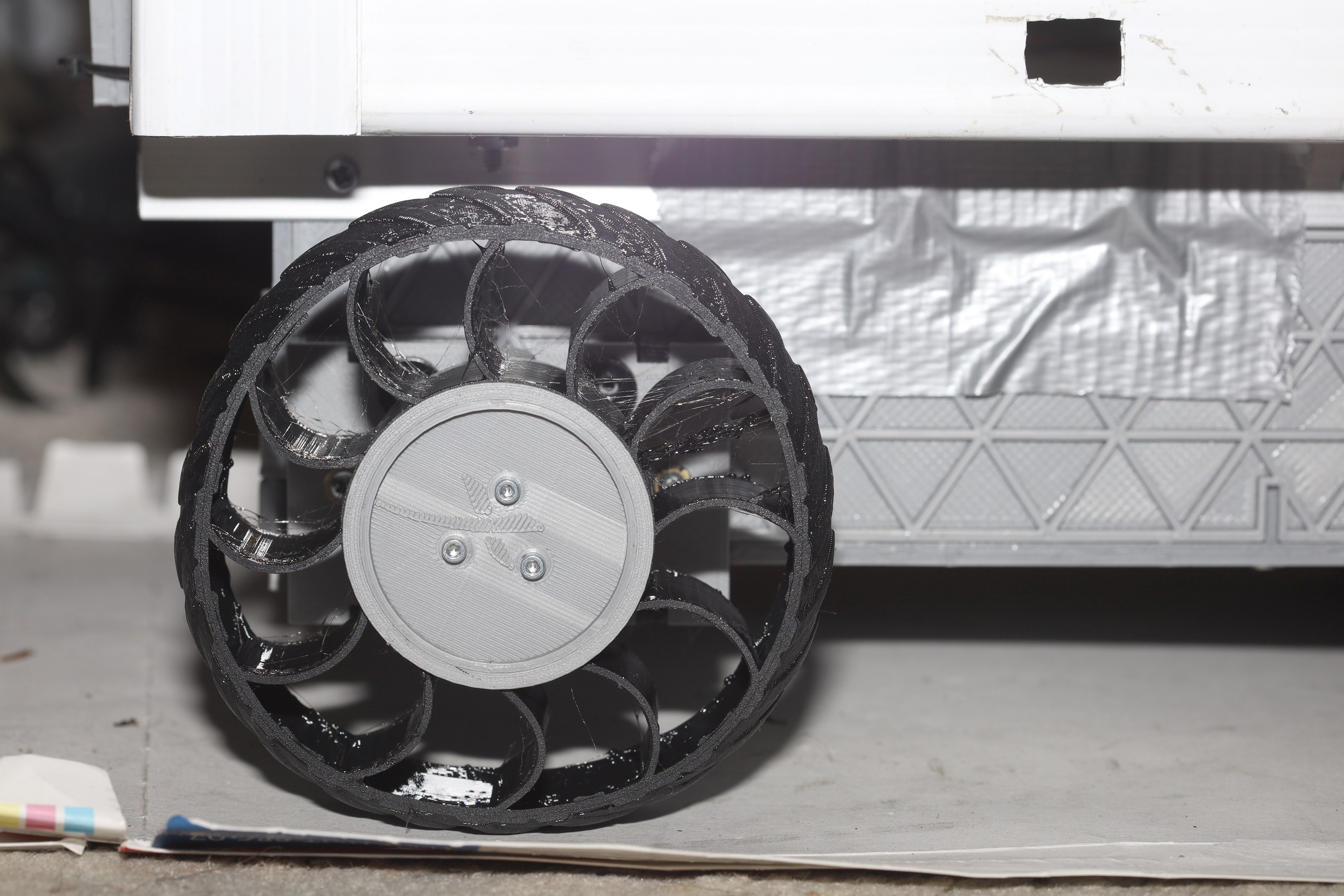
Tried adjusting the number & curving of the spokes to increase the hardness, but it's either going to require a lot of money or finite element analysis to get the perfect hardness. The compression of these tires means the tachometer reads much higher with a payload than without a payload.![]()
![]()
A new set of flat tread tires came off the printer. The increased contact patch in front didn't significantly increase power consumption, burning only 260mAh/mile with a full payload for half the distance. Helas, they're noisier. The increased contact area also increased how much the Z seams impact the road. These tires have much more pronounced Z seams because the tread is only 1mm thick. They're like paper, but TPU has proven much more durable than any rubber.
-
Radio upgrade
03/11/2021 at 18:55 • 0 commentsSo far, lions only used unamplified radios of 5mW on their own boards. Extended use of these radios has proven disastrous. Their range is only 15ft. The mane problem is near phone towers. The GSM bands overlap the 900Mhz ISM band so they die completely. Frequency hopping did nothing to improve it.
5mW was good enough for 13 years of indoor flying & stationary weather stations. When they're well above ground & using well aimed directional antennas, they can go 500ft. Thus, it was hoped they would be enough for outdoor driving.
There are only 2 low cost chip amplifiers on the digi key: the 1W SE2435 & the 500mW RFX1010. The lion kingdom went with the 500mW because it's much easier to hook up. As usual, it was a 2 week snail mail time. The limitation on power is the battery life. Some reduction of the output power or the duty cycle will be required to manage the battery life.
The XBee Pro 900 made 50mW & never had any dropouts when driving. It was worthless in the longer ranges required for flying, but it was flawless for driving. It was just too big to fit in the modern controller. It burned 210mA all out. The duty cycle got it down to 100mA.
The gold standard in the commercial world is the DJI Mavic, which only transmits 400mW. The top end Spektrums only transmit 7mW at 2.4Ghz. They obviously rely on directionality.The mane problem with getting any more power is the small form factor, small battery, & not being able to use a directional antenna.
![]()
The upgraded board was a bodgeorama, but it was the lion kingdom's 1st home made transmitter above 5mW.
The trick with the RFX1010 is the antenna input is shorted to ground at DC. It needs a 33pF blocking capacitor. Then, when the transmit enable pin is on, it burns over 150mA with no input. When the transmit enable pin is off, it burns nothing. This pin needs to be actively turned off when not transmitting. Receive enable & mode have to be grounded to get it to completely shut down. The control pins are floating. Mercifully, the switching time is only 1us.
Then of course, the high power requirement of the amplifier caused problems. The ADC became unreliable when the amplifier ran. Making it use the dedicated RC oscillator got it to work for some reason. The LP2989 voltage regulator got stuck on 2.5V until it got a 100uF input cap.
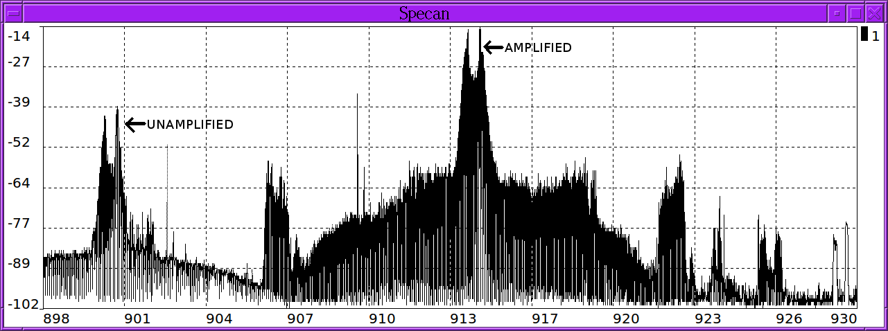
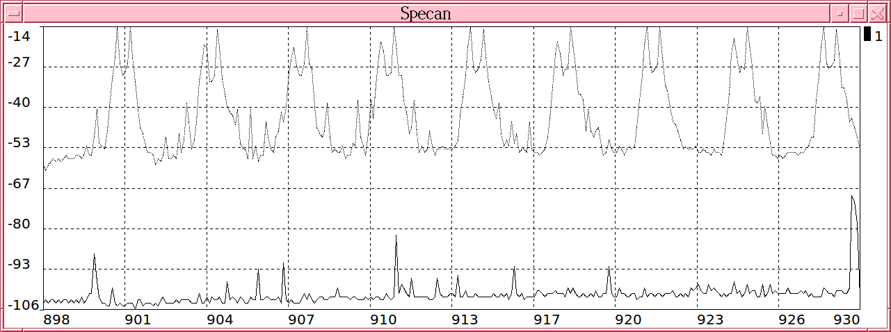
When it finally worked, it only burned 50mA for the full .5W. The duty cycle was low enough to use full power. Frequency shift keying is clearly visible on the spectrogram.
![]()
![]()
The 9 discrete channels used in the frequency hopping mode are clearly visible on the spectrograms.
![]()
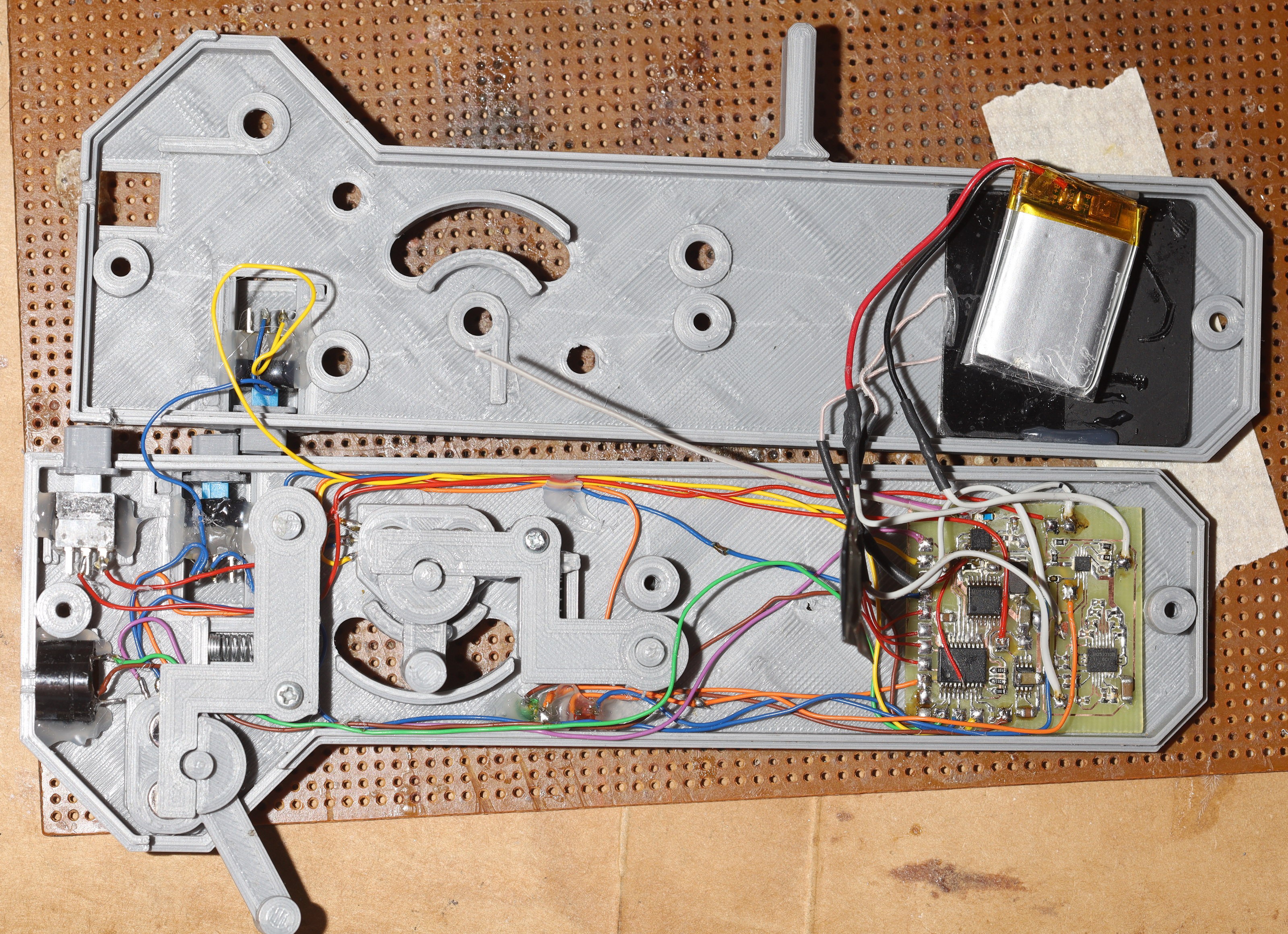
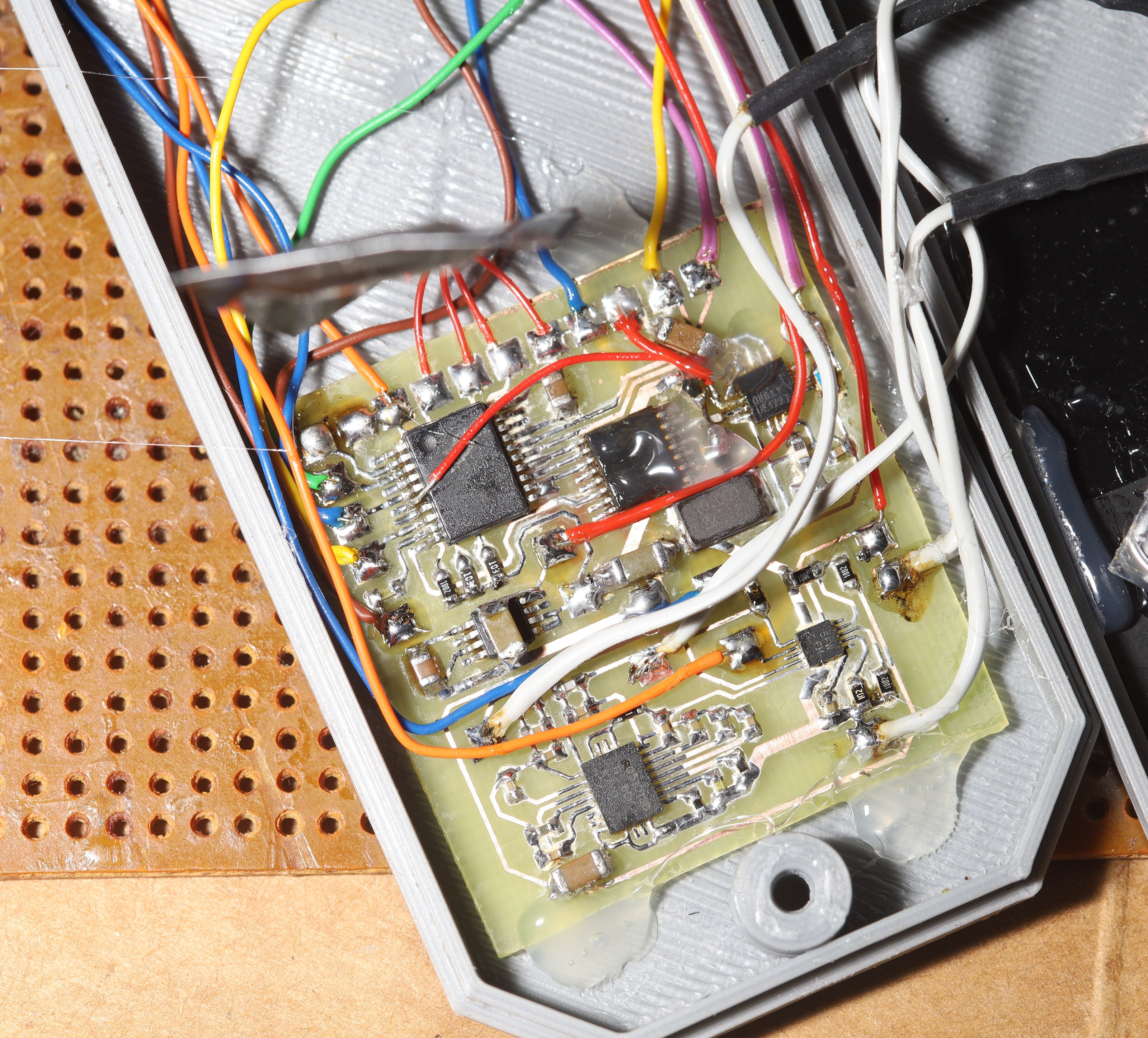
The fully populated board.
![]()
![]()
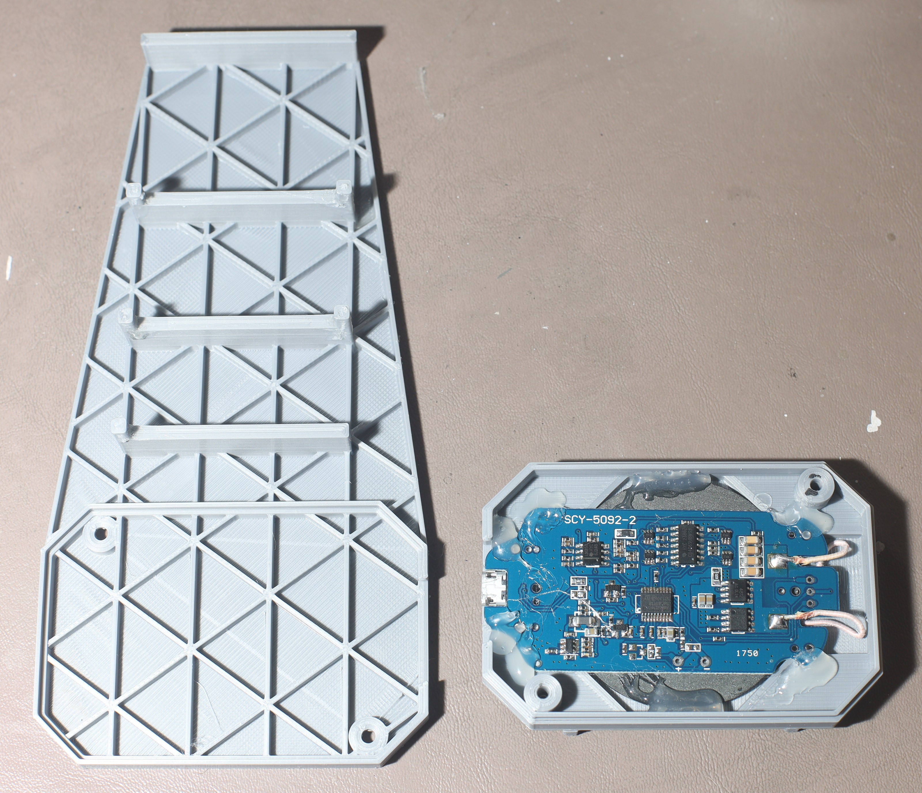
Testing the battery charger, LED, & speaker. Testing is essential, since it's not reworkable in the enclosure.
![]()
![]()
![]()
Bench testing was ugly, with much worse results than the unamplified radio. It seemed to be saturating the receiver. Moving it farther away or covering it improved reception. Hot glued the bodge wires down instead of making a new board. Buttoned it up & it worked much better in the field. It managed to fend off the phone tower & range was no longer a problem. There were still dropped packets near the phone tower but not enough to kill it.
The impedance matching is obviously horrendous. Having the receiver right next to the ground is horrendous. The lion kingdom was just hoping for enough improvement to do the job. The battery has to be charged after every drive now. It took 30 minutes to hit constant voltage on the inductive charger. Something would have to be rigged out of a multimeter to get the number of coulombs.
The big question is exactly how much power it's radiating, compared to a Spektrum or a DJI. It spreads the 500mW across 100kbits. The Spektrums concentrate 7mW in a very narrow bandwidth so they have long range. The DJI video transmitter radiates 1W across a 20Mhz band of frequencies, so it has shorter range. No-one knows what the DJI uses for remote control. It may be the same as the Spektrum.
This leaves the gyro glitches & the erratic speed. I2C needs to be done in software. That was how lions made it more reliable, 10 years ago.
-
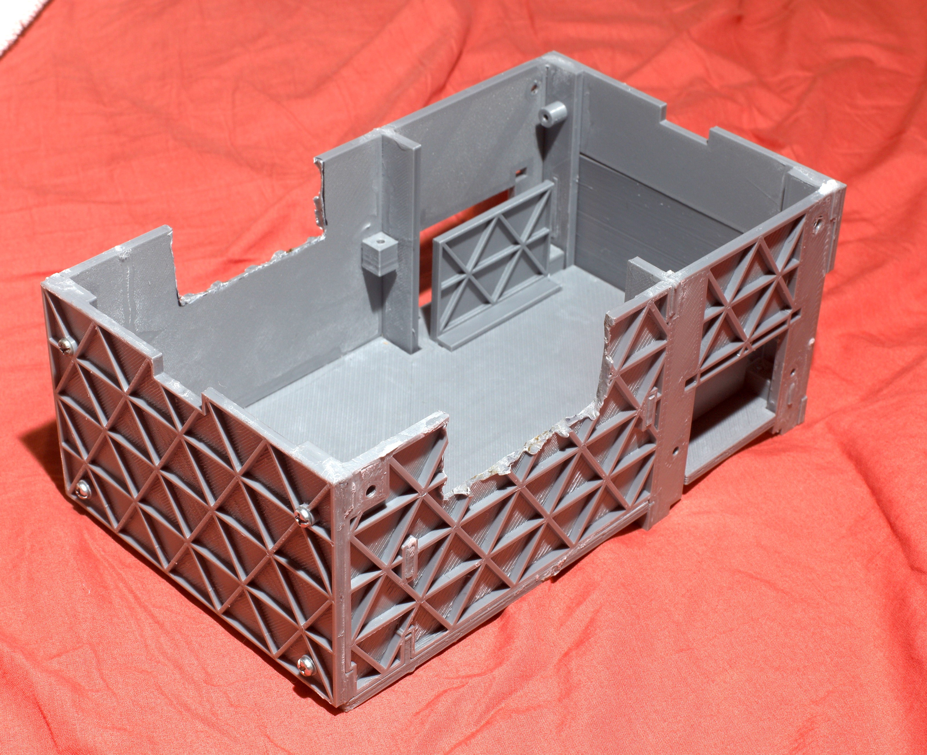
New Container
02/19/2021 at 05:08 • 0 commentsAfter a minor tweek to the firmware to make it easier to calibrate the motors, the traction module didn't have any problems. The ship was at a point where further improvement would require exponential amounts of money. Bigger motors would be the 1st upgrade, but super expensive. Higher voltage batteries would be a cheaper but still expensive option.
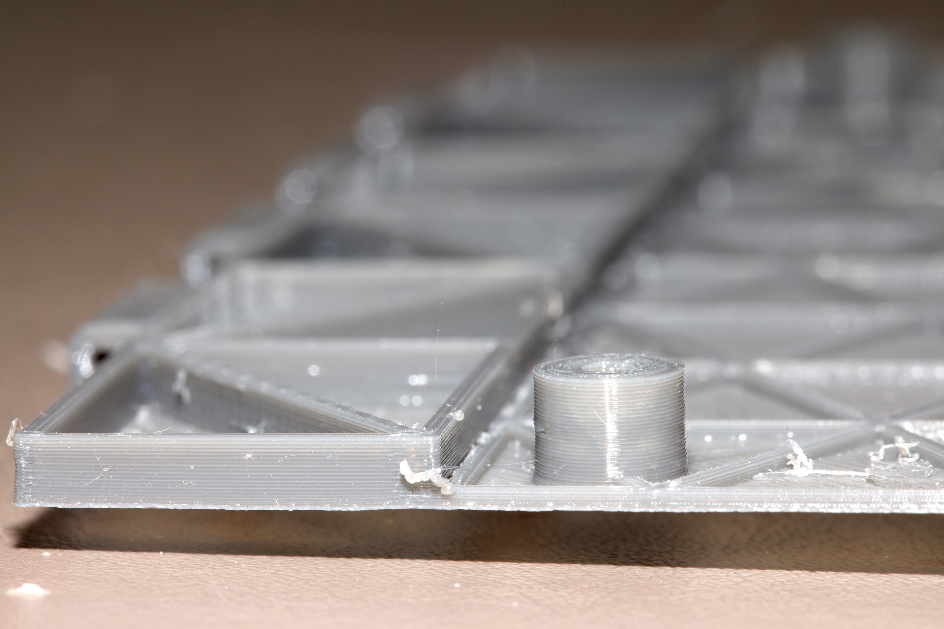
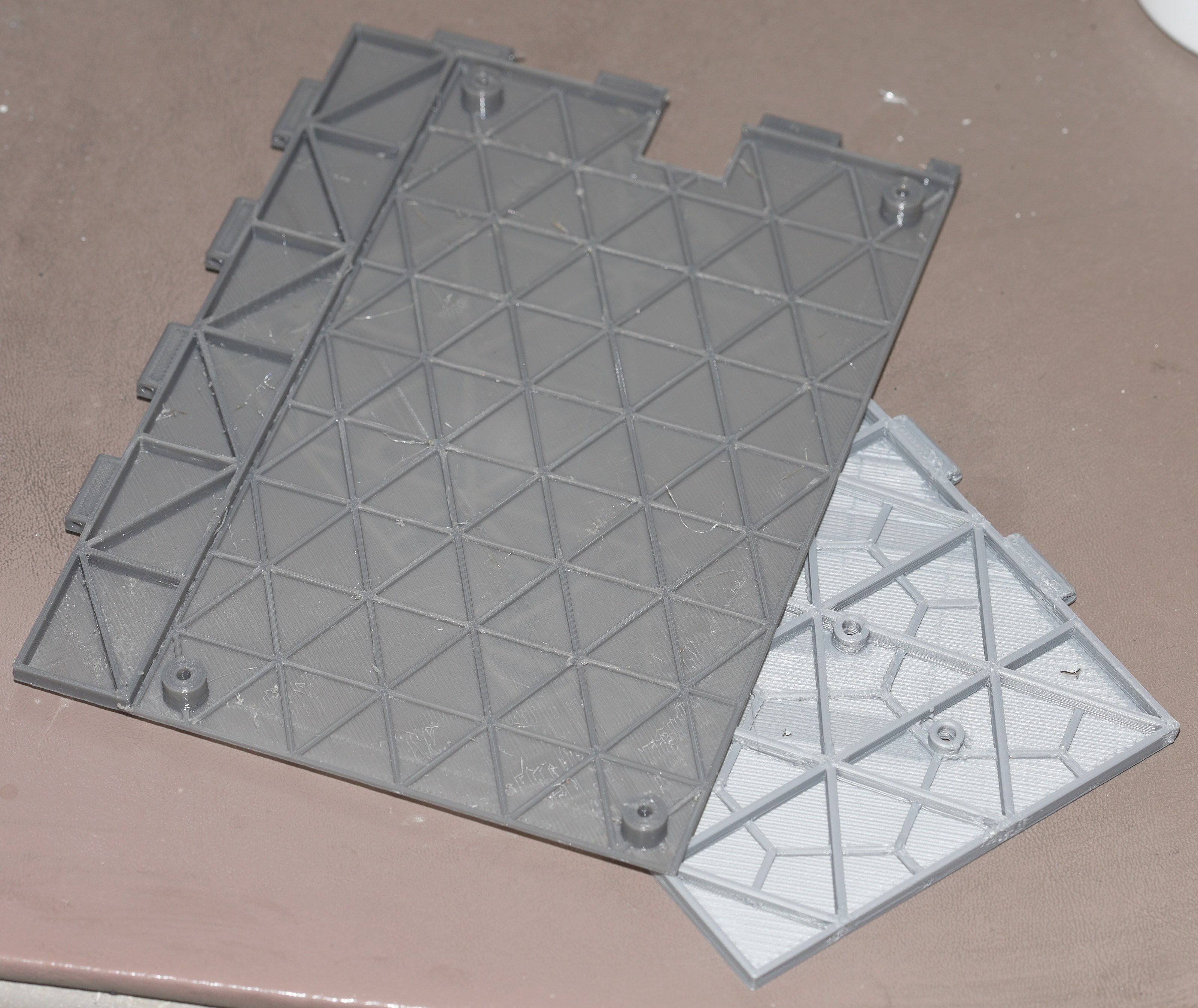
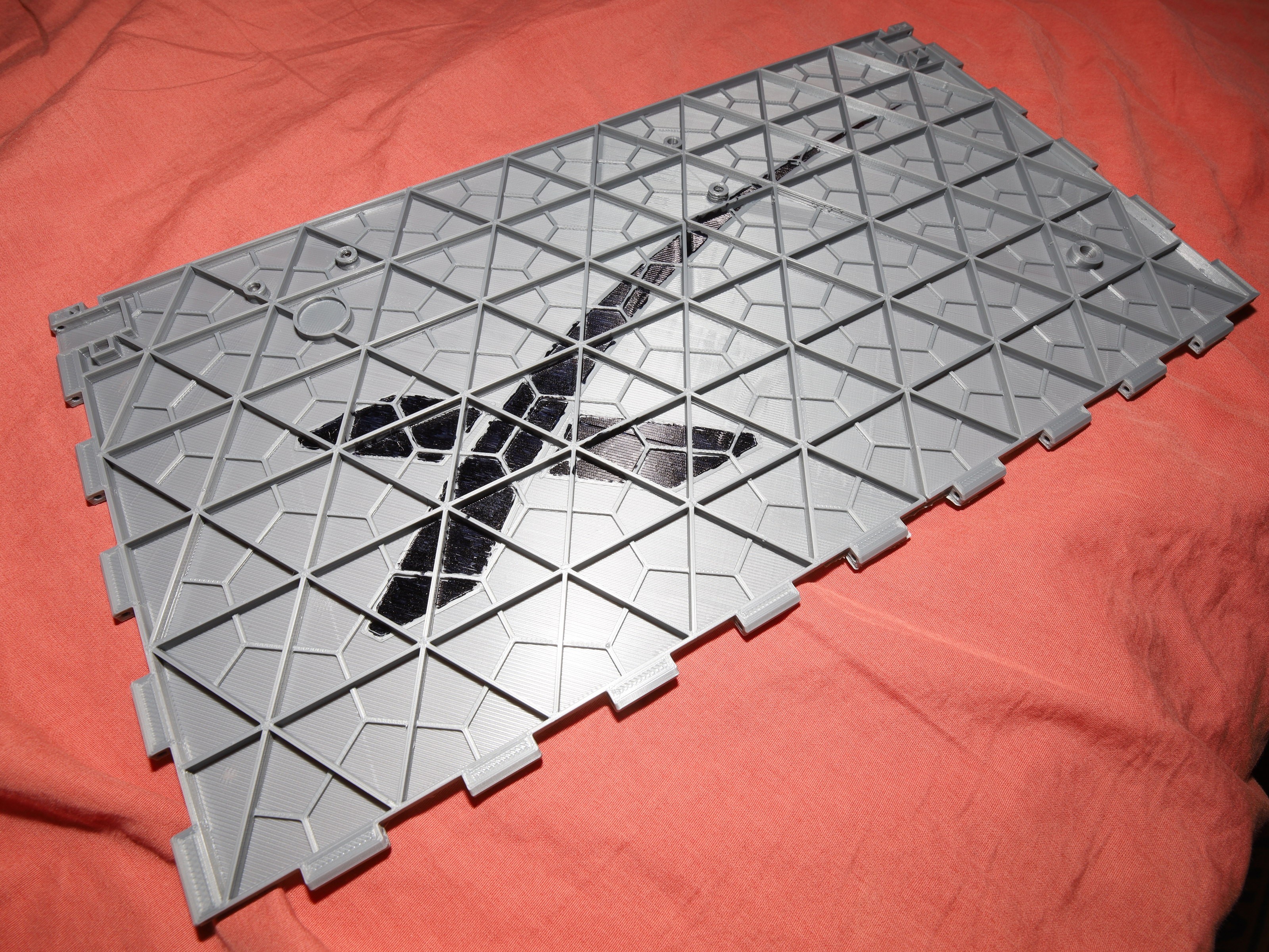
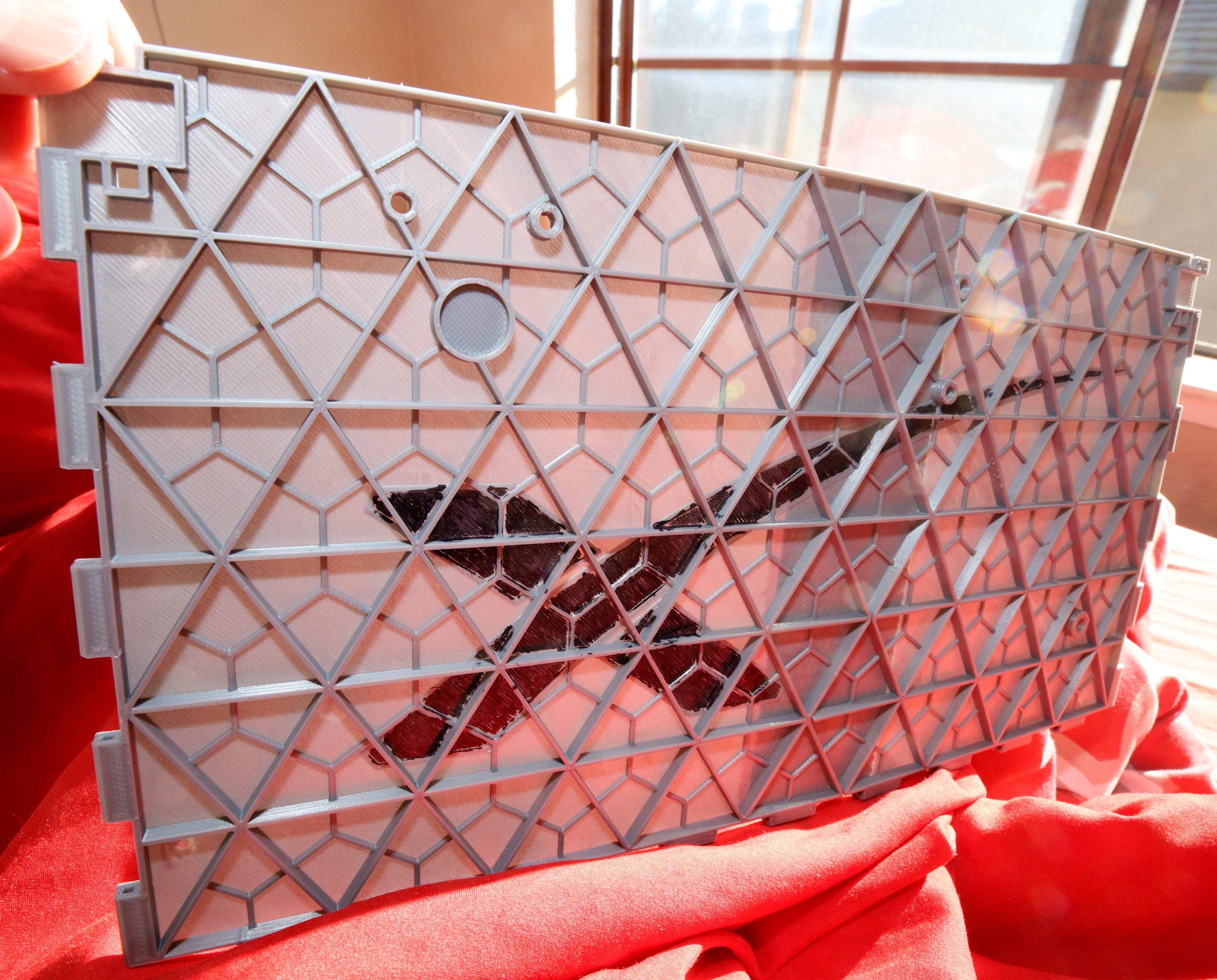
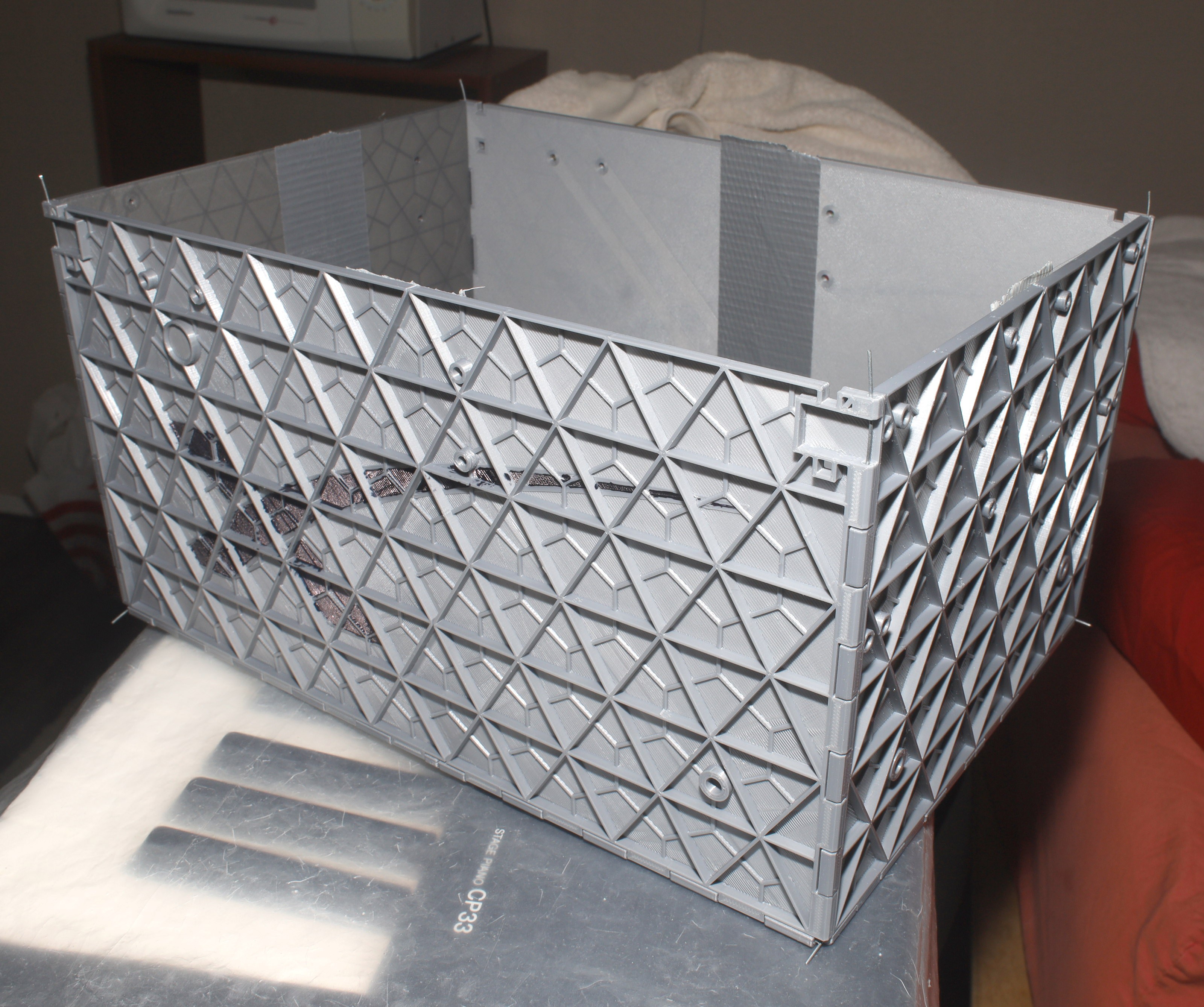
The container is the weakest link. Nothing is lighter than coroplastic. The 1st container out of 1.2mm panels was a brick. Lions have since printed most panels as .8mm thick. There was some intriguing work to print .2mm panels out of .06mm layers. That would be below the Ender 3's bed deformations. .4mm panels out of .2mm layers with isogrids might work.
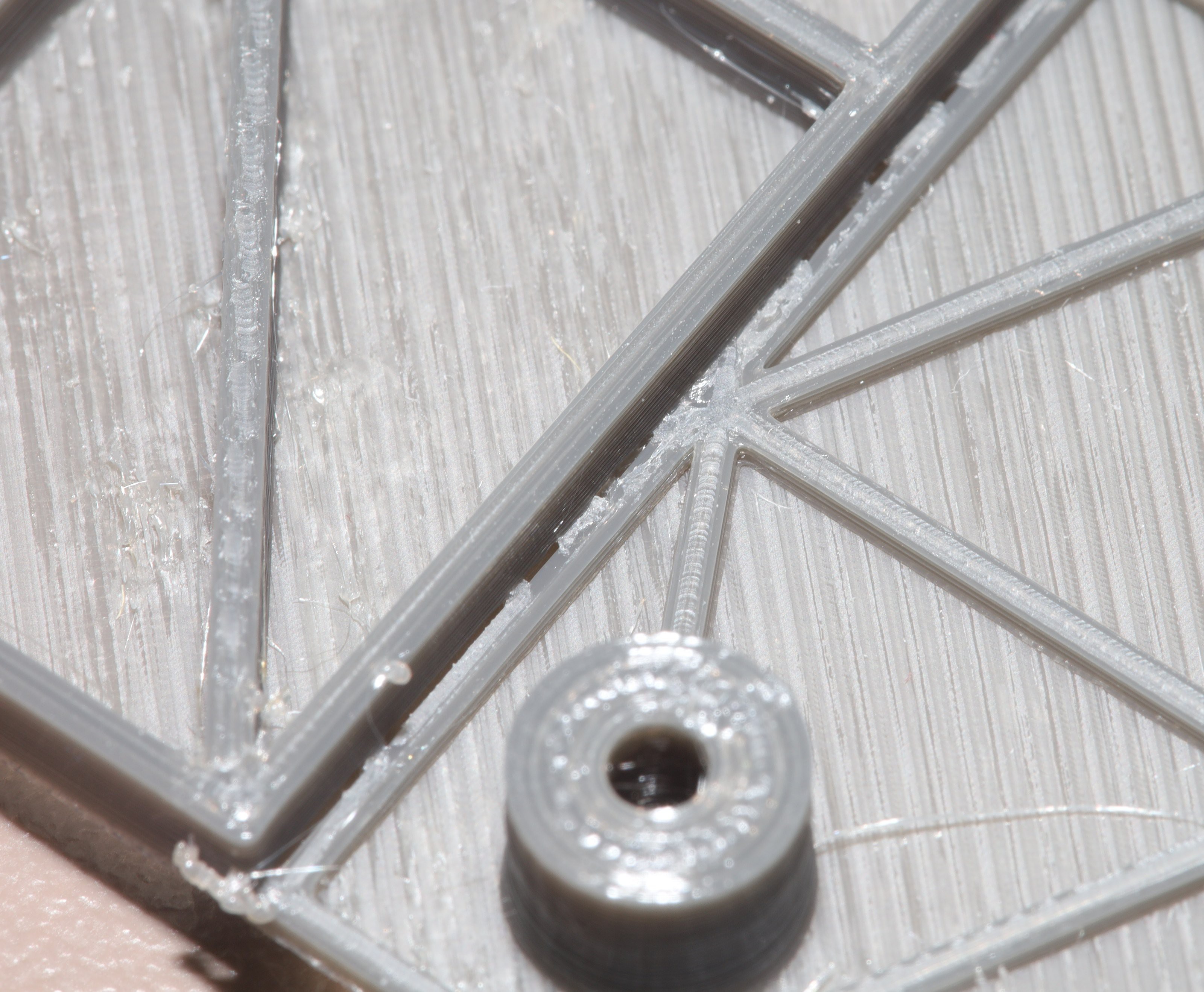
A variety of test panels were printed out of PETG & PLA. They were .4mm thick backings & 3.6mm thick isogrids. They had to be printed with a .4mm nozzle to minimize the weight, which took much longer than a .8mm nozzle.
![]()
![]()
![]()
Cura failed to slice an upside down overhang, leaving out a top shell.
![]()
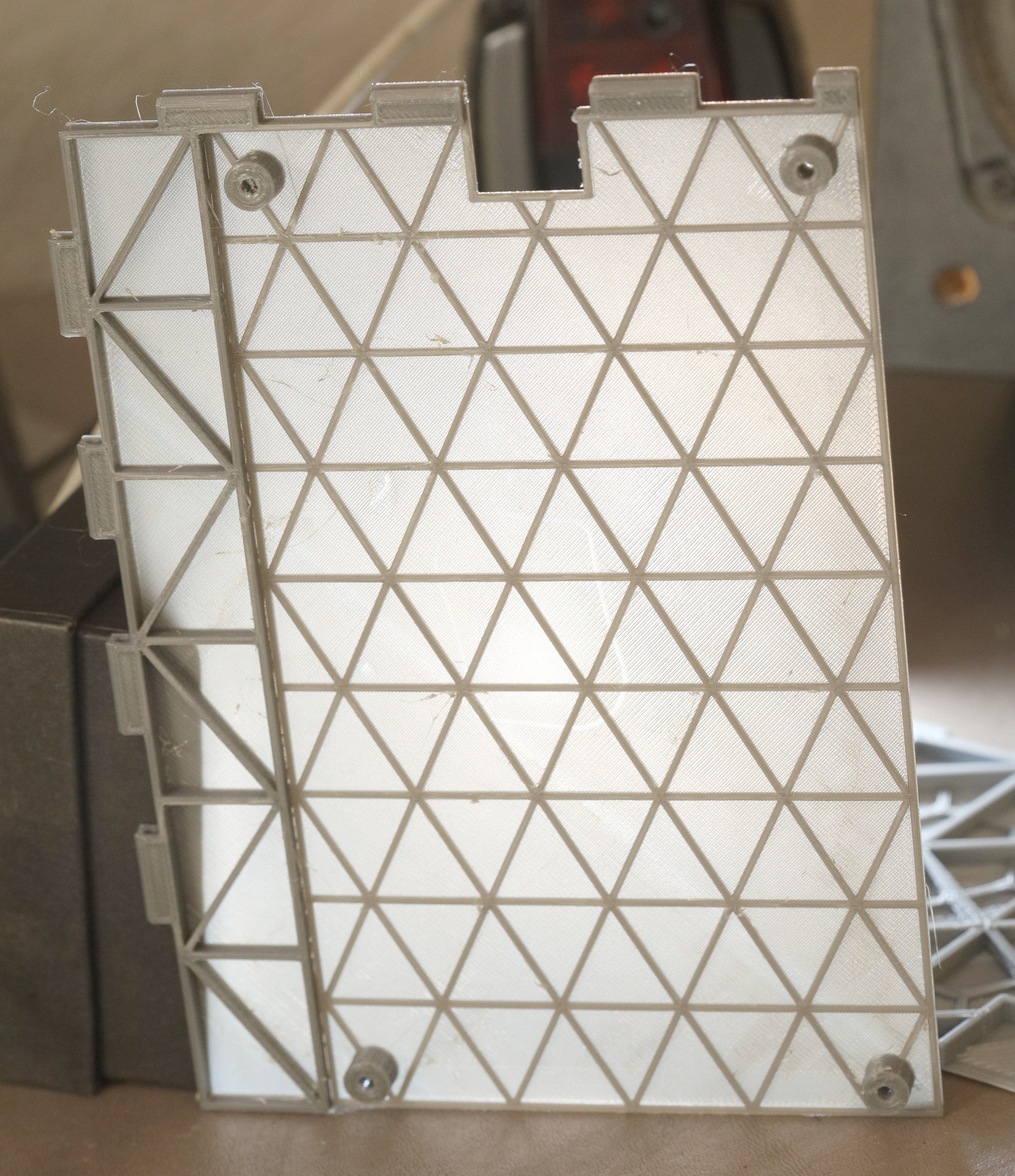
The .4mm panels were quite translucent & light, but about as strong as a single side of coroplastic. PETG was a failure in both strength & weight, but it was more resistant to heat. It would be a good material for motor encoders but not panels. The panels would stay good old PLA.
![]()
The mane test was poking it with a screwdriver. The trick with the .4mm panels was to set up the bed leveling game. There couldn't be any squishing of the 1st layer. A better way to get the 1st layer to stick without squishing it was to wash the bed in dishwashing soap. Skin oil was the enemy of adhesion.
![]()
![]()
![]()
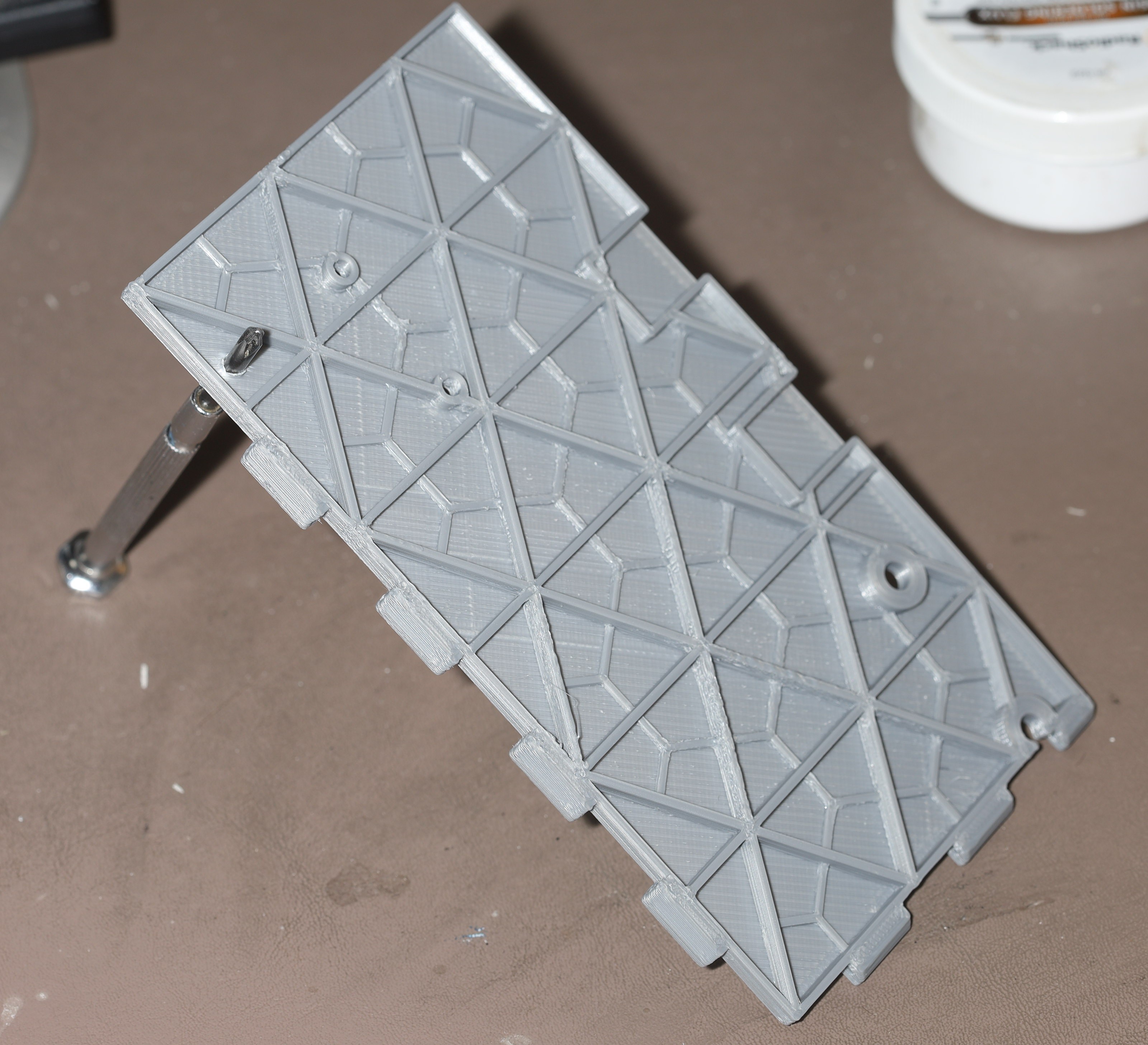
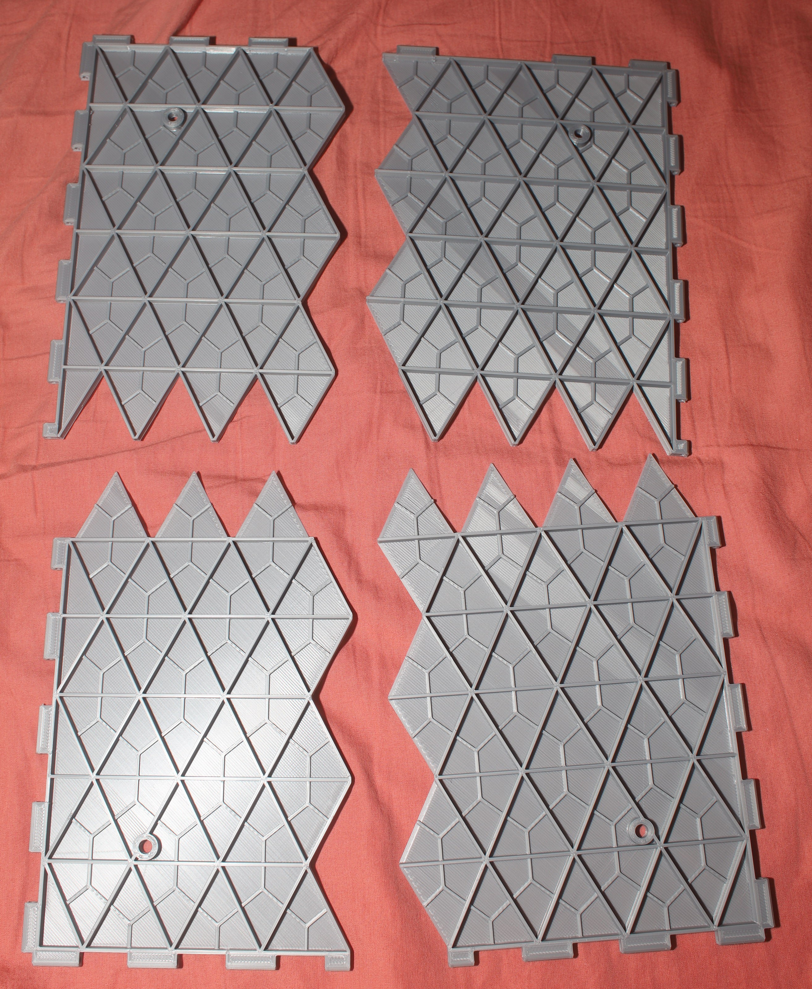
Over several days, panels slowly churned out. A new painting scheme using a sharpie was somewhat successful. It had a hard time getting into the corners between the isogrid lines. A raised border didn't do as good a job at confining the ink as raised painted areas, but raising the painted areas would use more material.
![]()
![]()
![]()
![]()
![]()
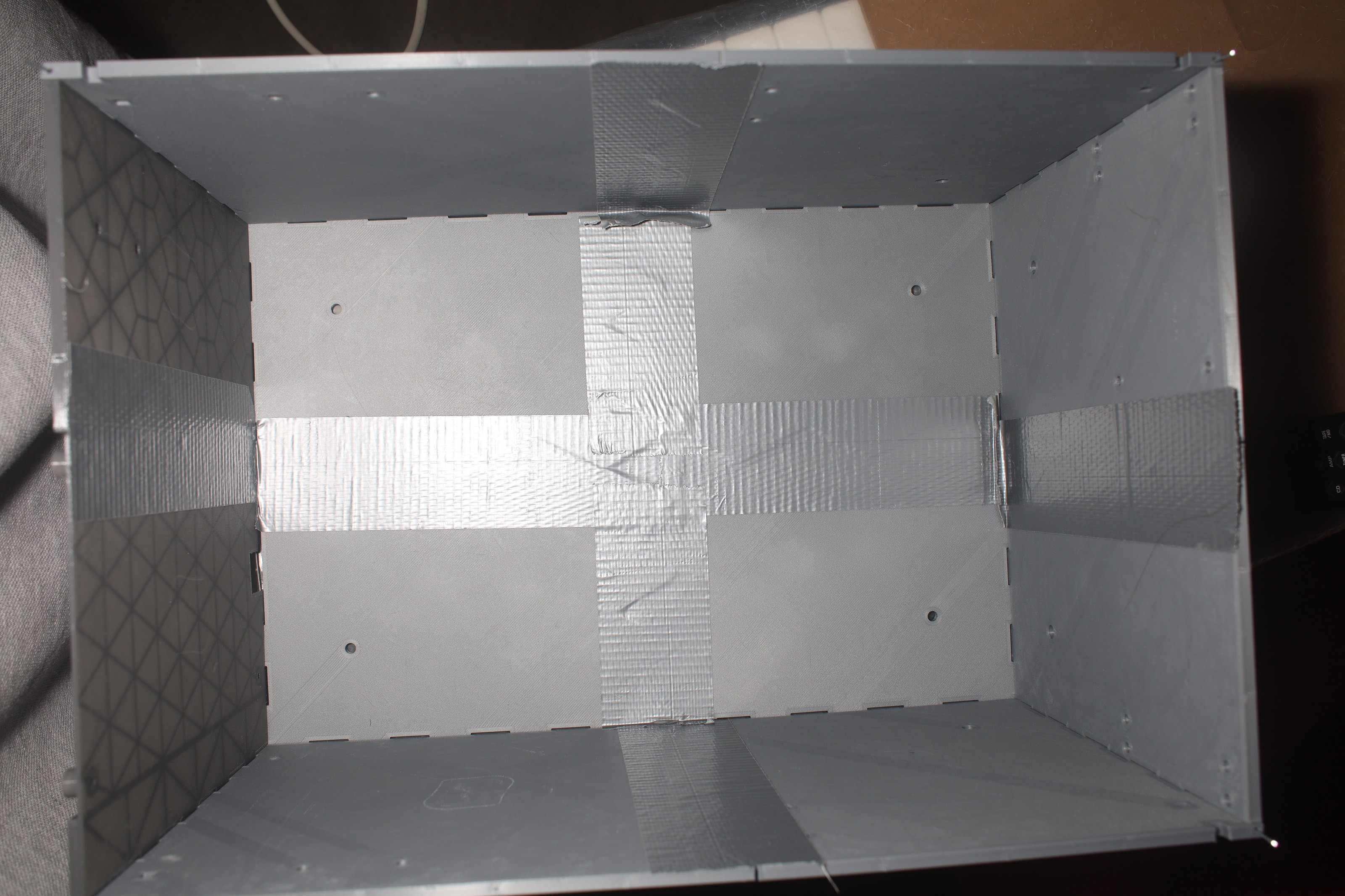
This would be easier with a larger printer, but lacking $20 million for a larger room for a larger printer, the panels would be duct taped initially. Later, a 2nd layer of .4mm PLA panels would be printed & glued in. Printing essentially duct tape is a waste of 3D printing, but the cheapest way of doing it.
![]()
![]()
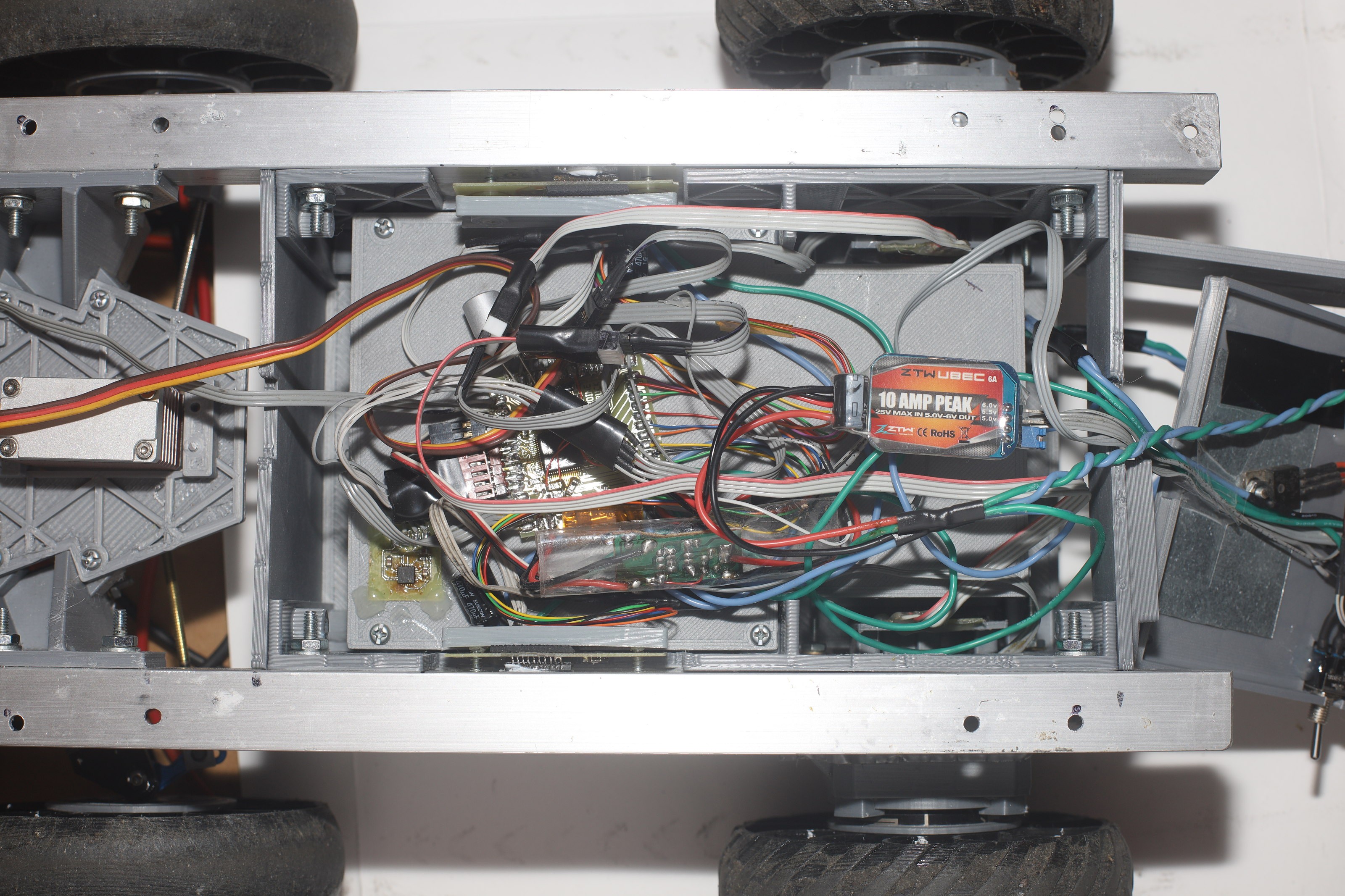
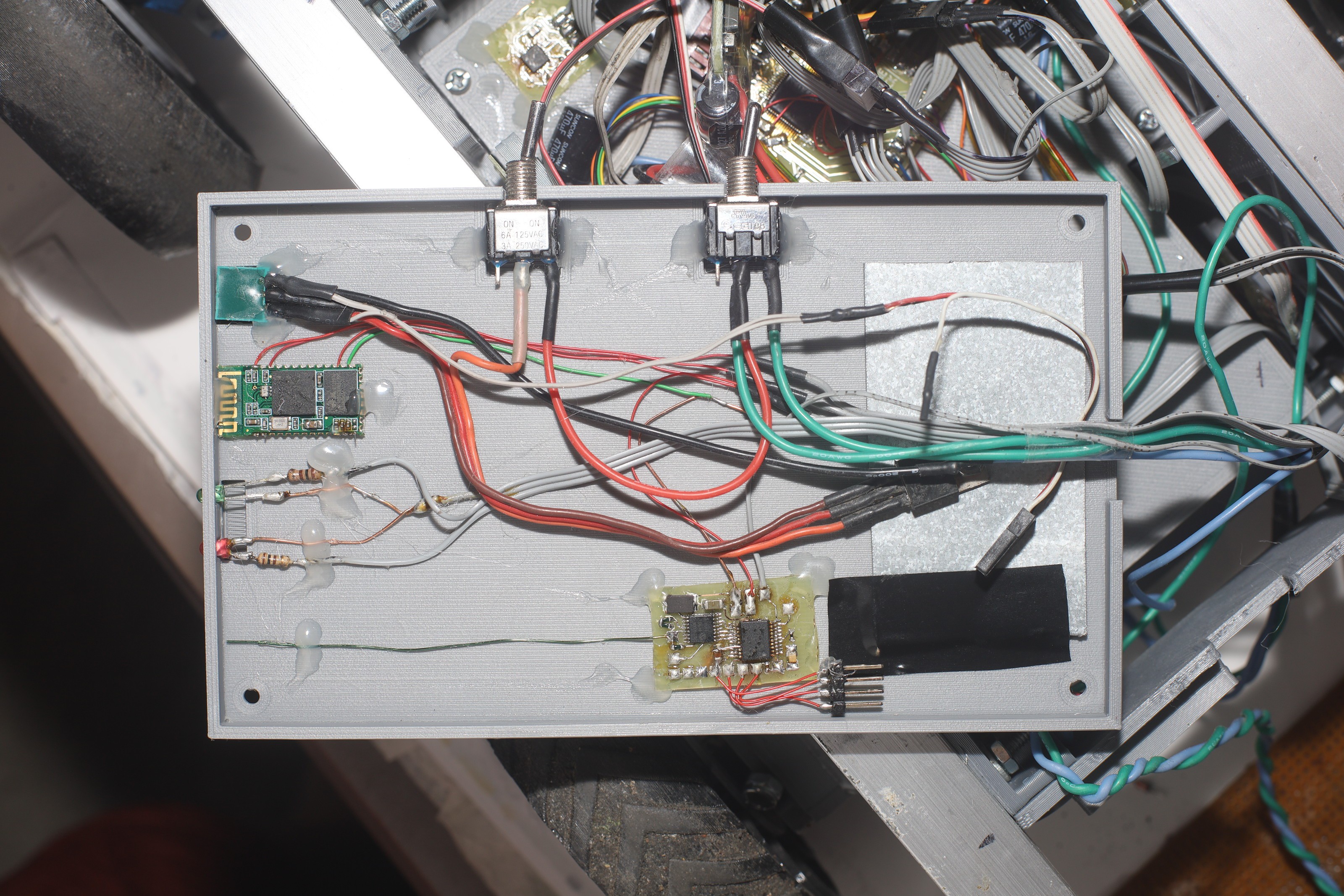
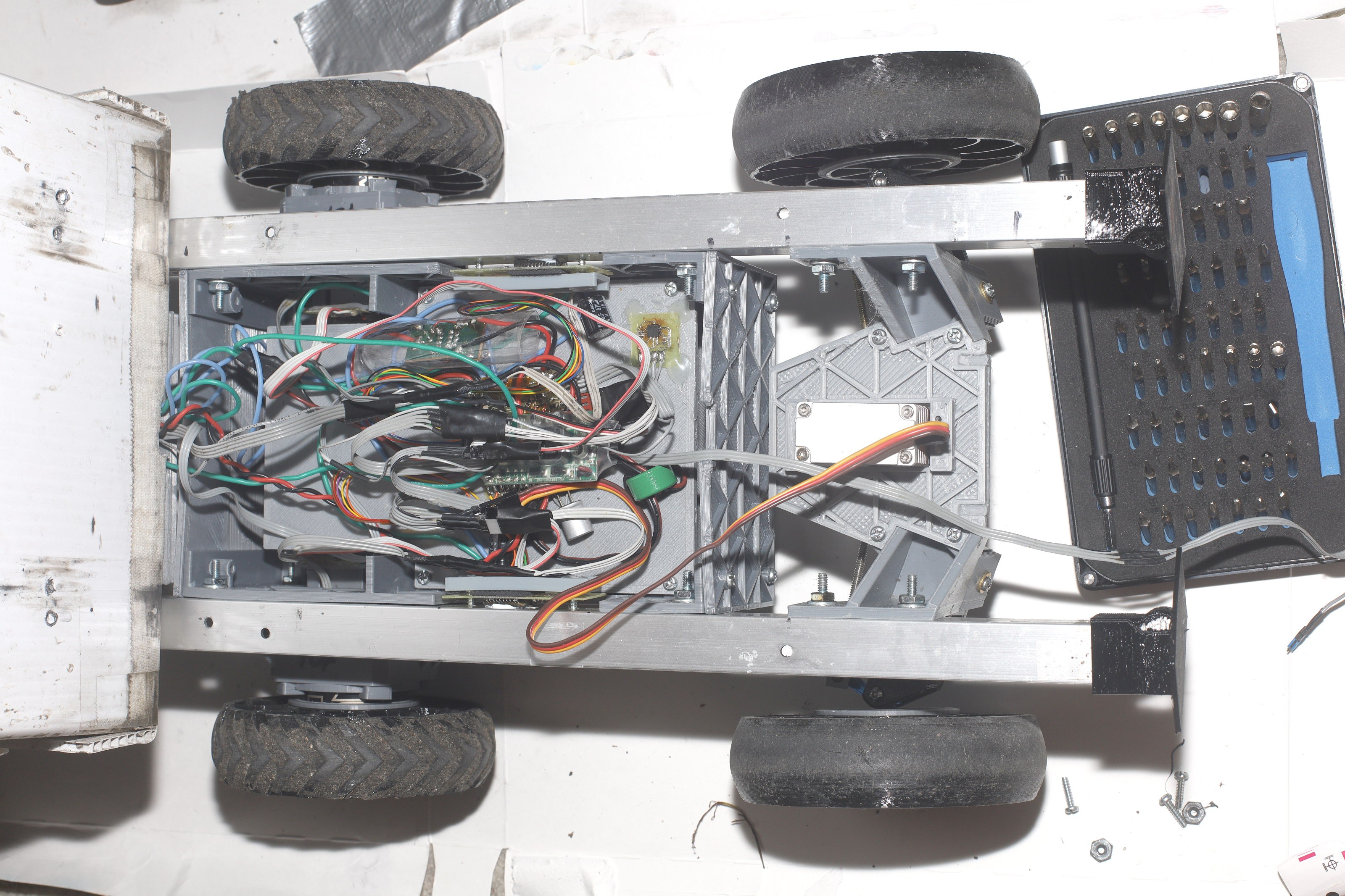
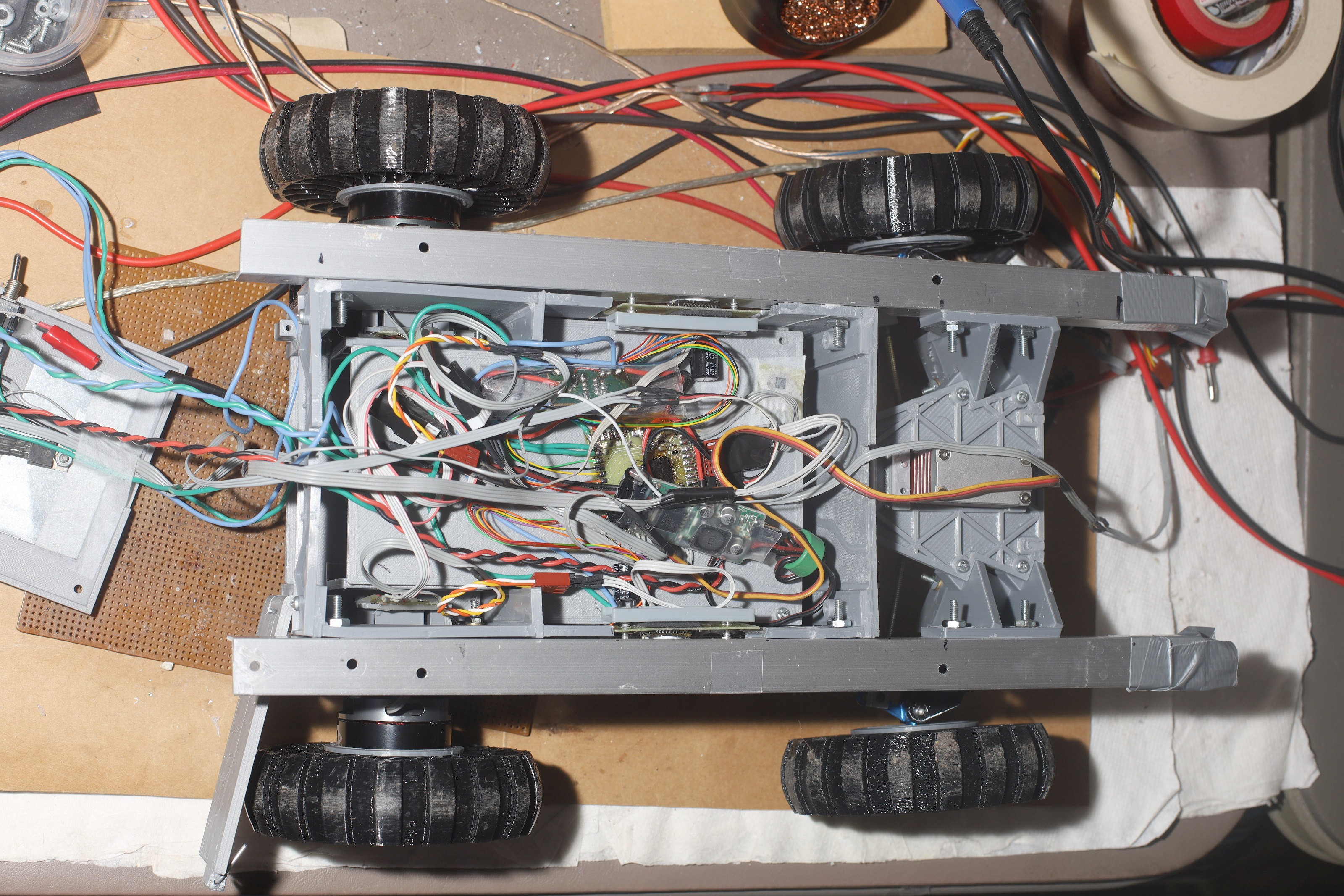
The electronics got a proper 6A buck converter to replace the crummy 3A Turnigies which are taking over the world. The 3A was not enough to drive the steering servo. The radios got transferred into a new .4mm panel.
![]()
![]()
![]()
![]()
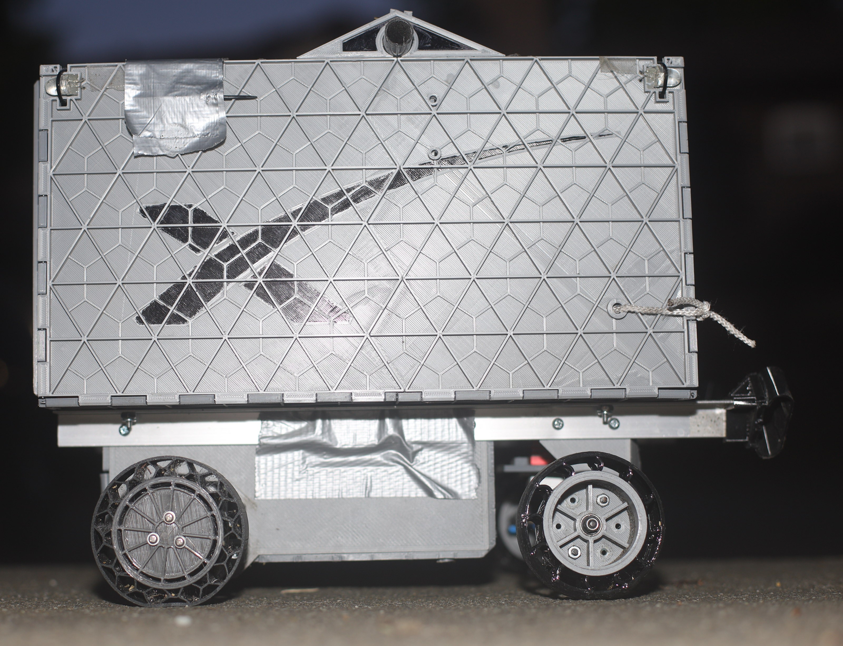
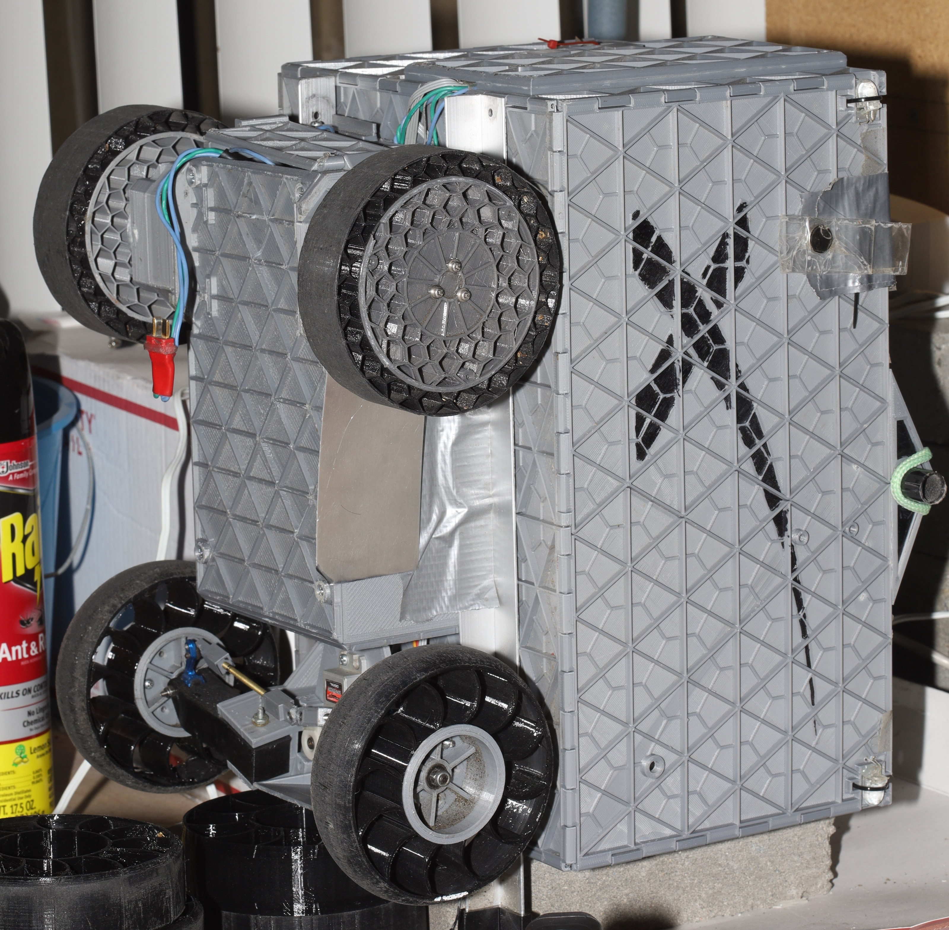
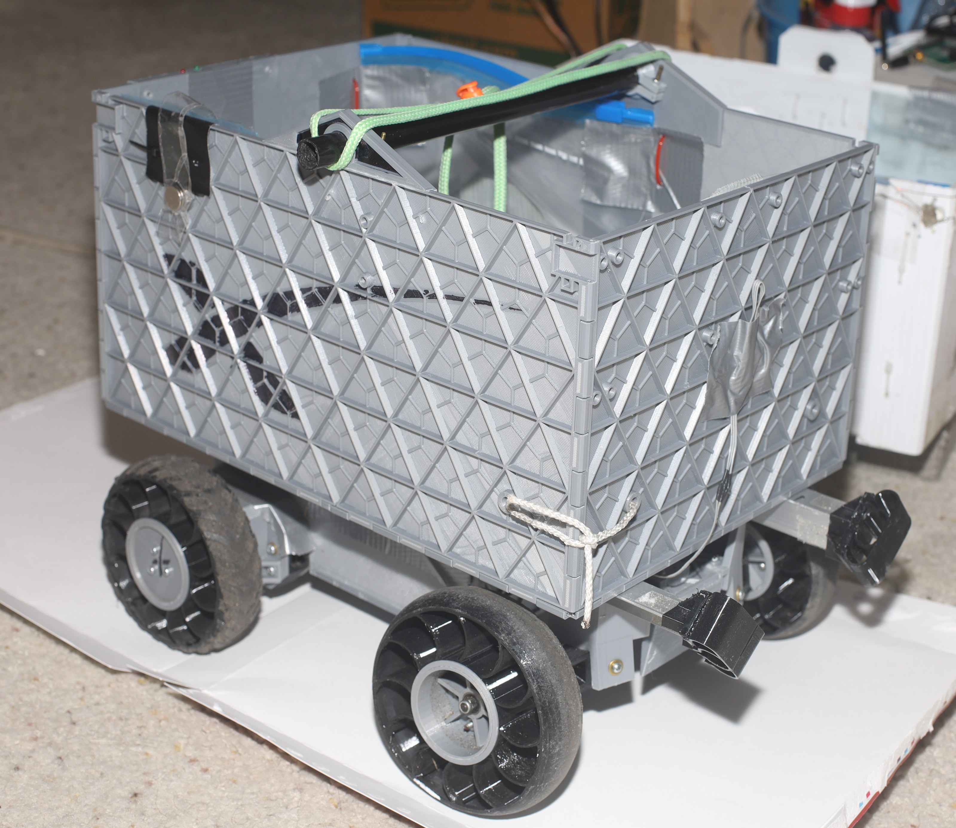
The container worked quite well & was much more visually appealing than the coroplastic of 5 years. It's noisier than coroplastic, but still nowhere close to the noise of a gearbox. The mane problem is the headlight attachments. There are wires farstening the corners together, but the wires can't extend through the headlights. The corners with the headlights remane unfastened & a bit loose. How to farsten the corners while still having headlights is still a work in progress.
![]()
The 2nd set of bumpers broke, so a 3rd set of bumpers were printed. TPU can't flex between the laminations without delaminating. The laminations had to be rotated.
![]()
![]()
This was the 1st attempt at adhering TPU. CA with tongues & grooves was the best method, but it was never as effective on TPU as PLA.
-
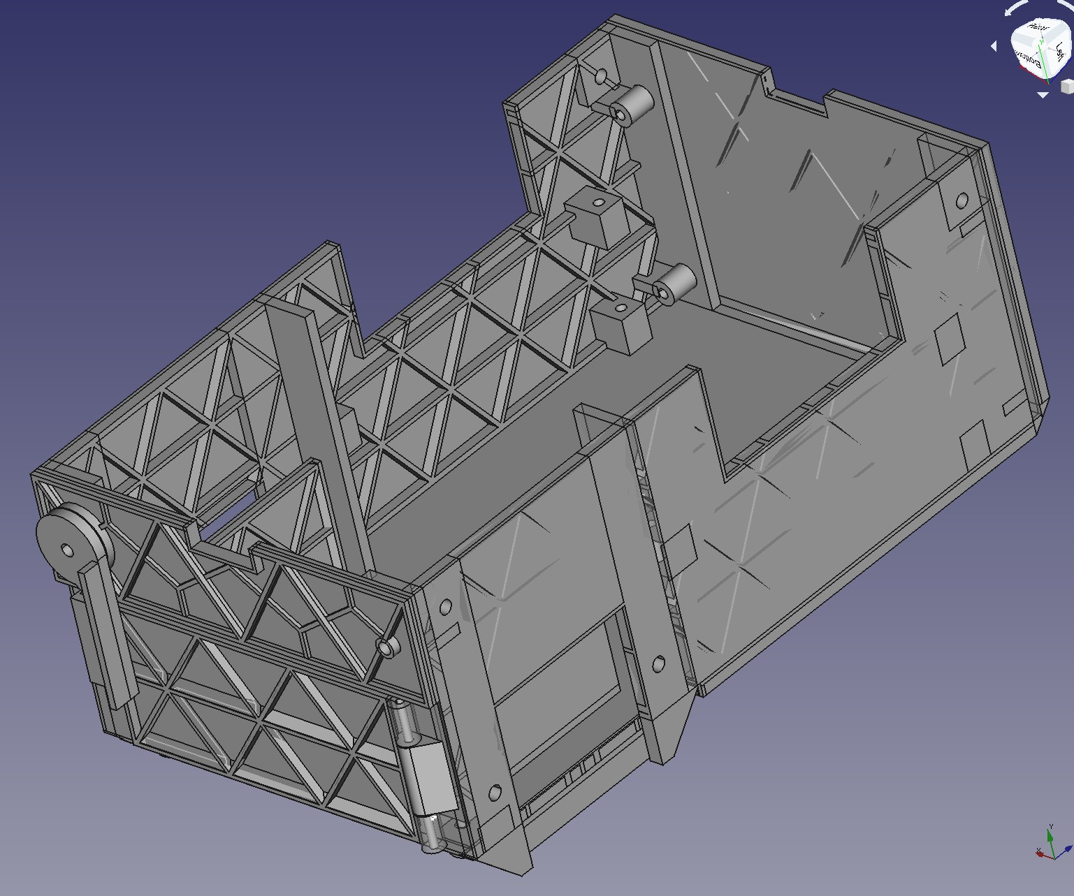
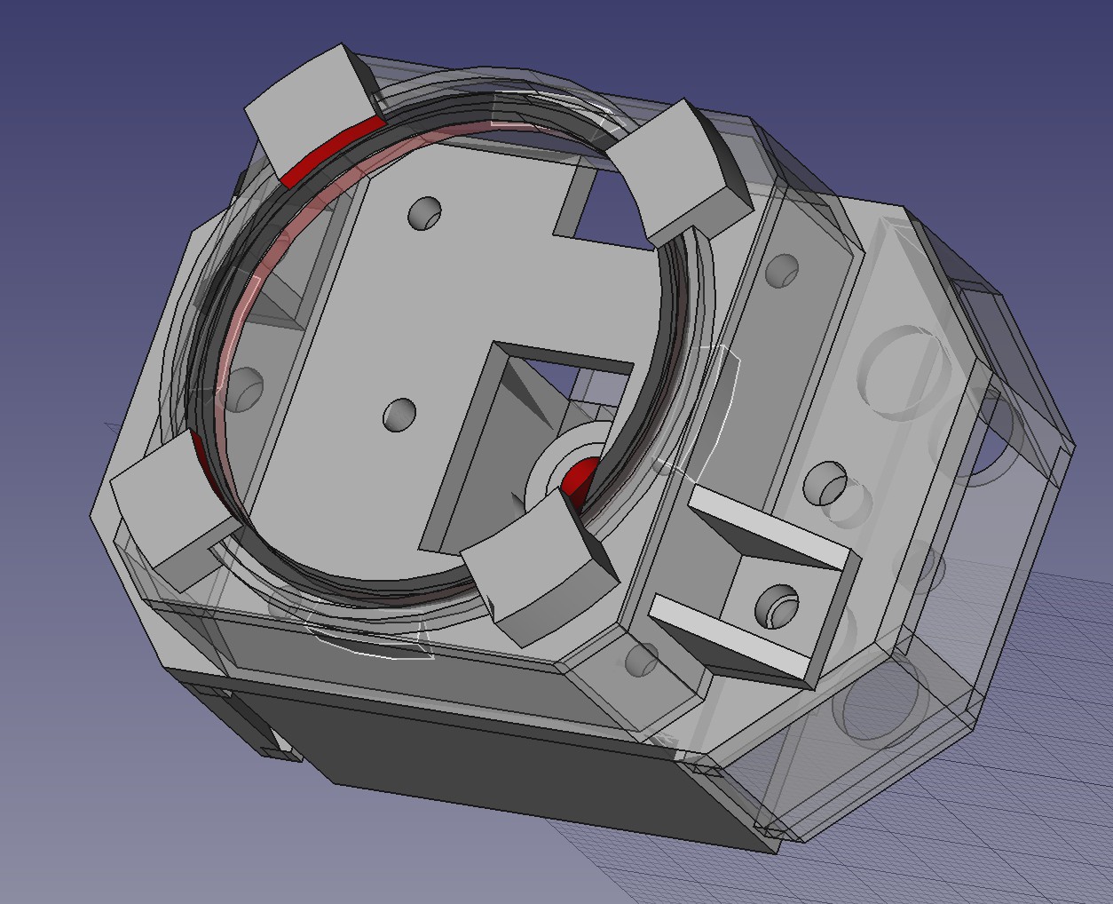
Traction module 3
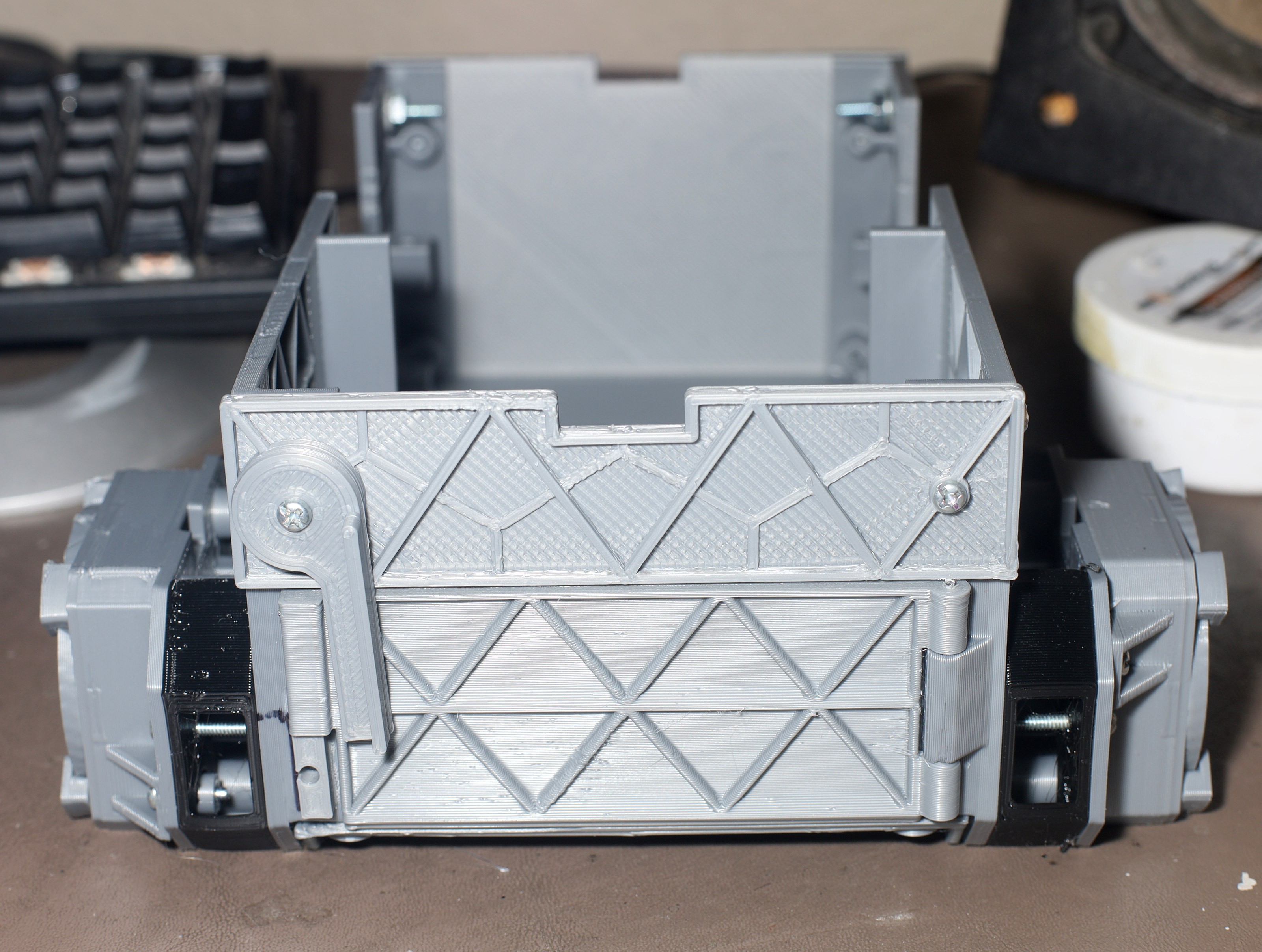
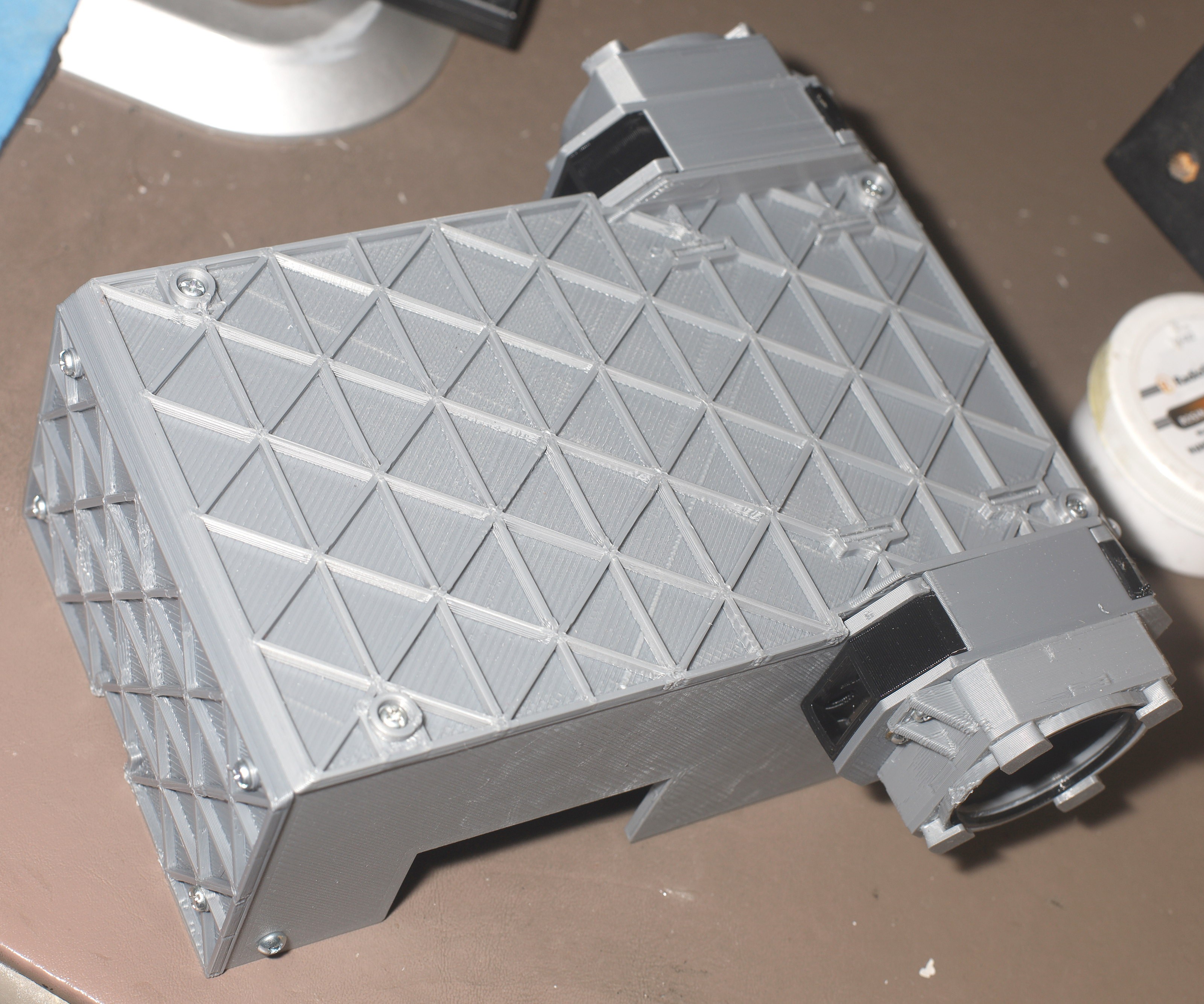
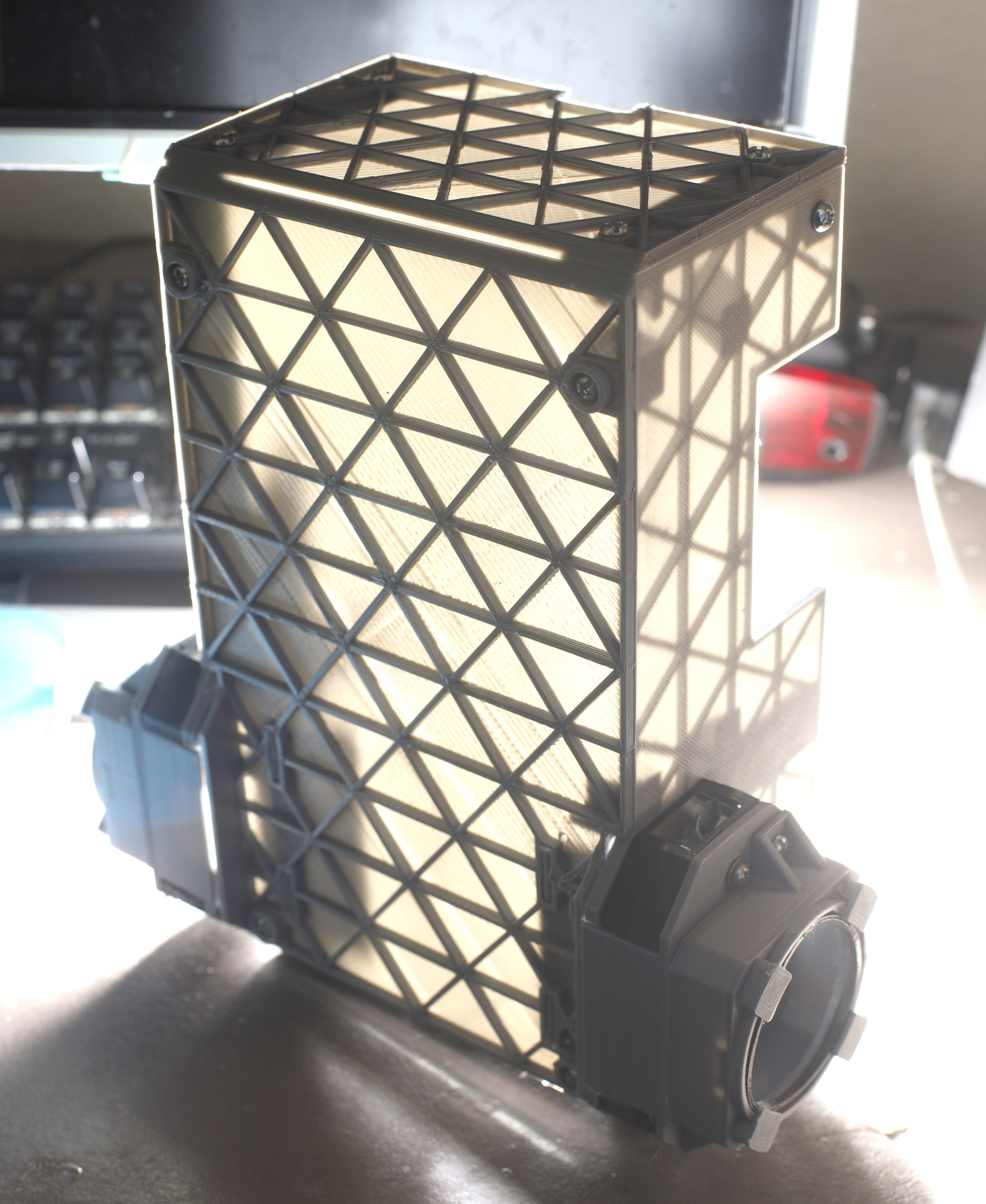
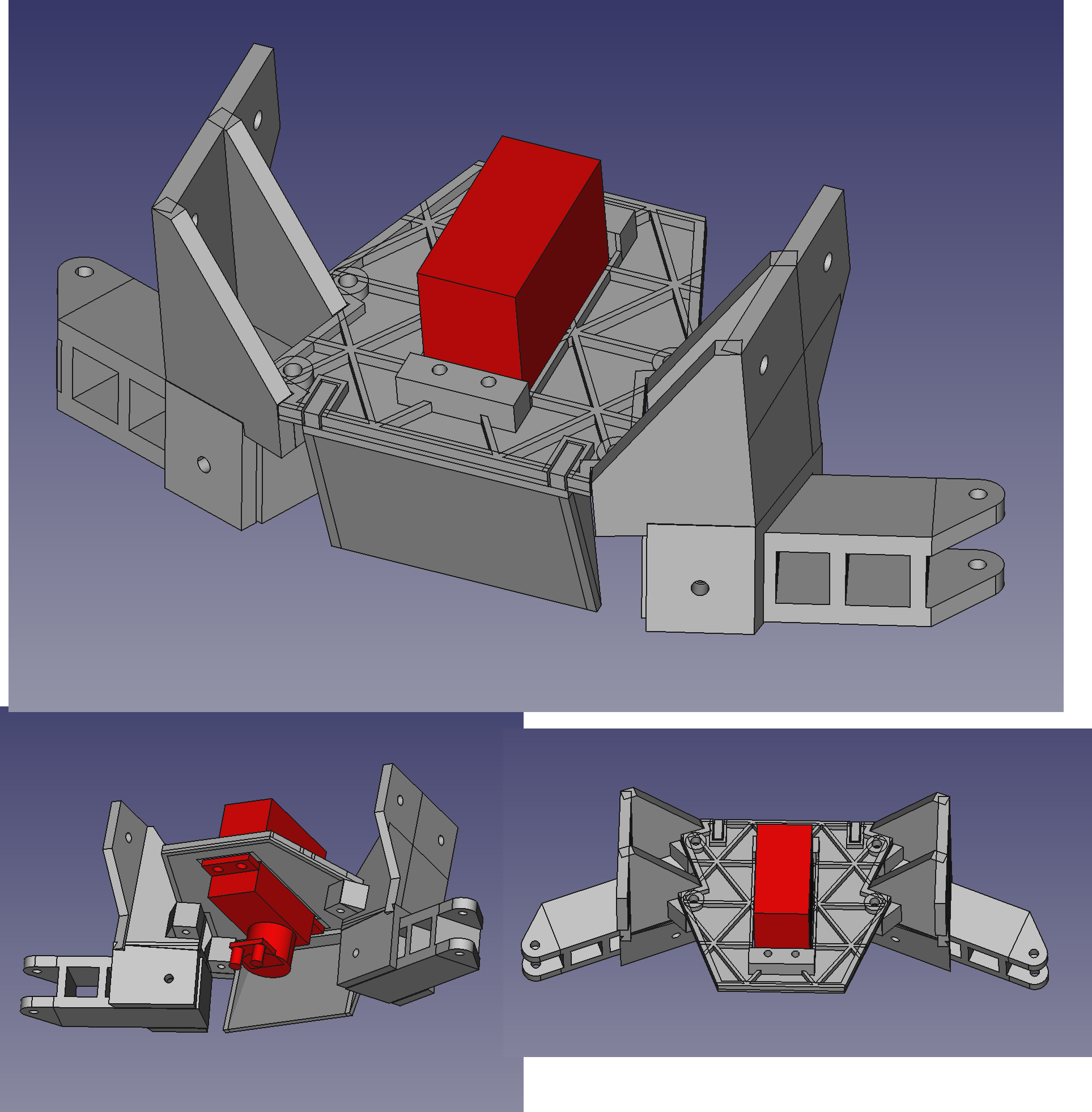
02/10/2021 at 06:57 • 0 commentsRock intrusion continued to plague the motors, so a new traction module was designed, to fully enclose the motors.
![]()
![]()
![]()
![]()
![]()
![]()
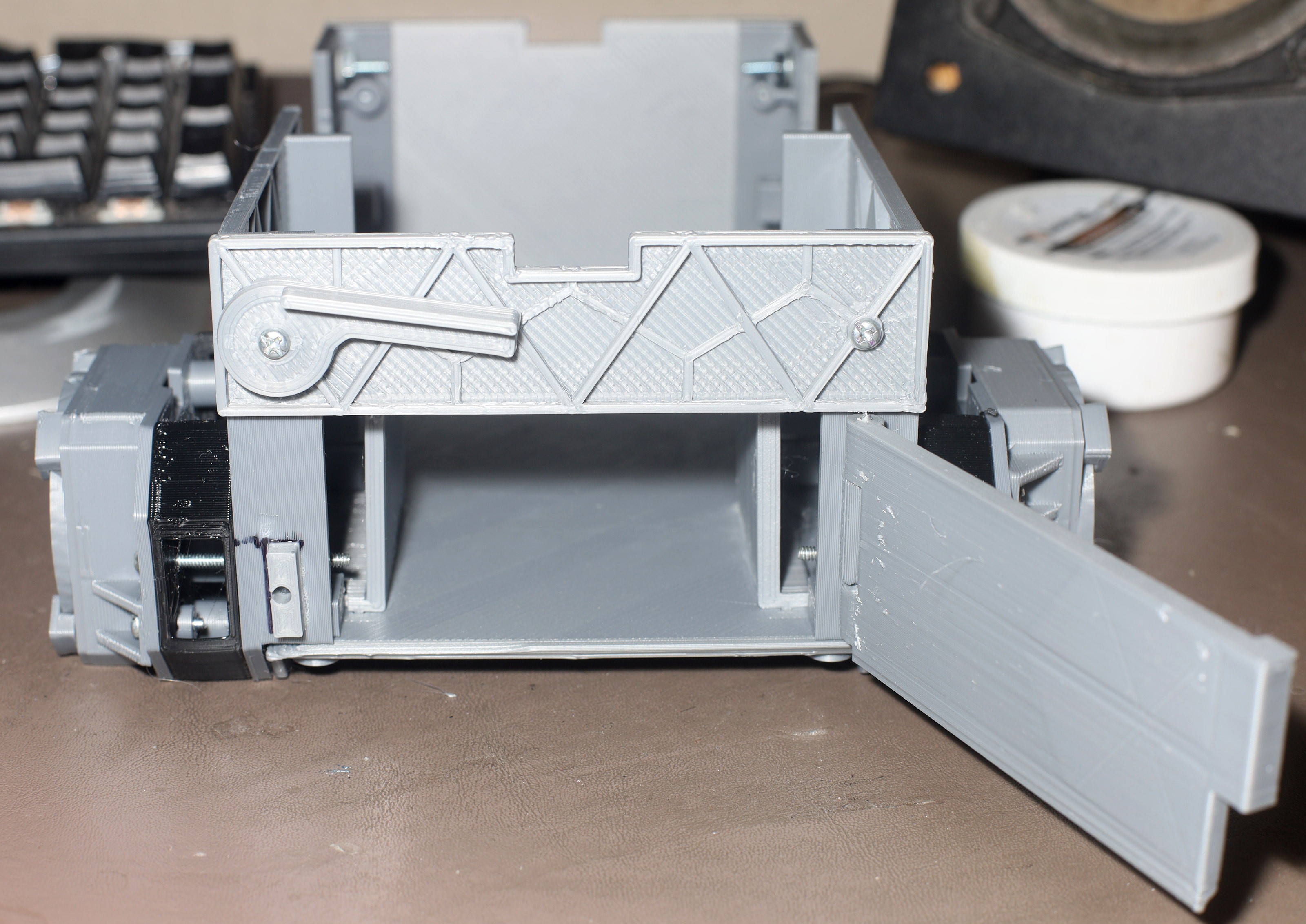
This one flipped the isogrid panels so the sides could be printed in 1 piece. It was sized for a .8mm line width, .32mm layer height. The reduced part count made it fit much more accurately.
![]()
![]()
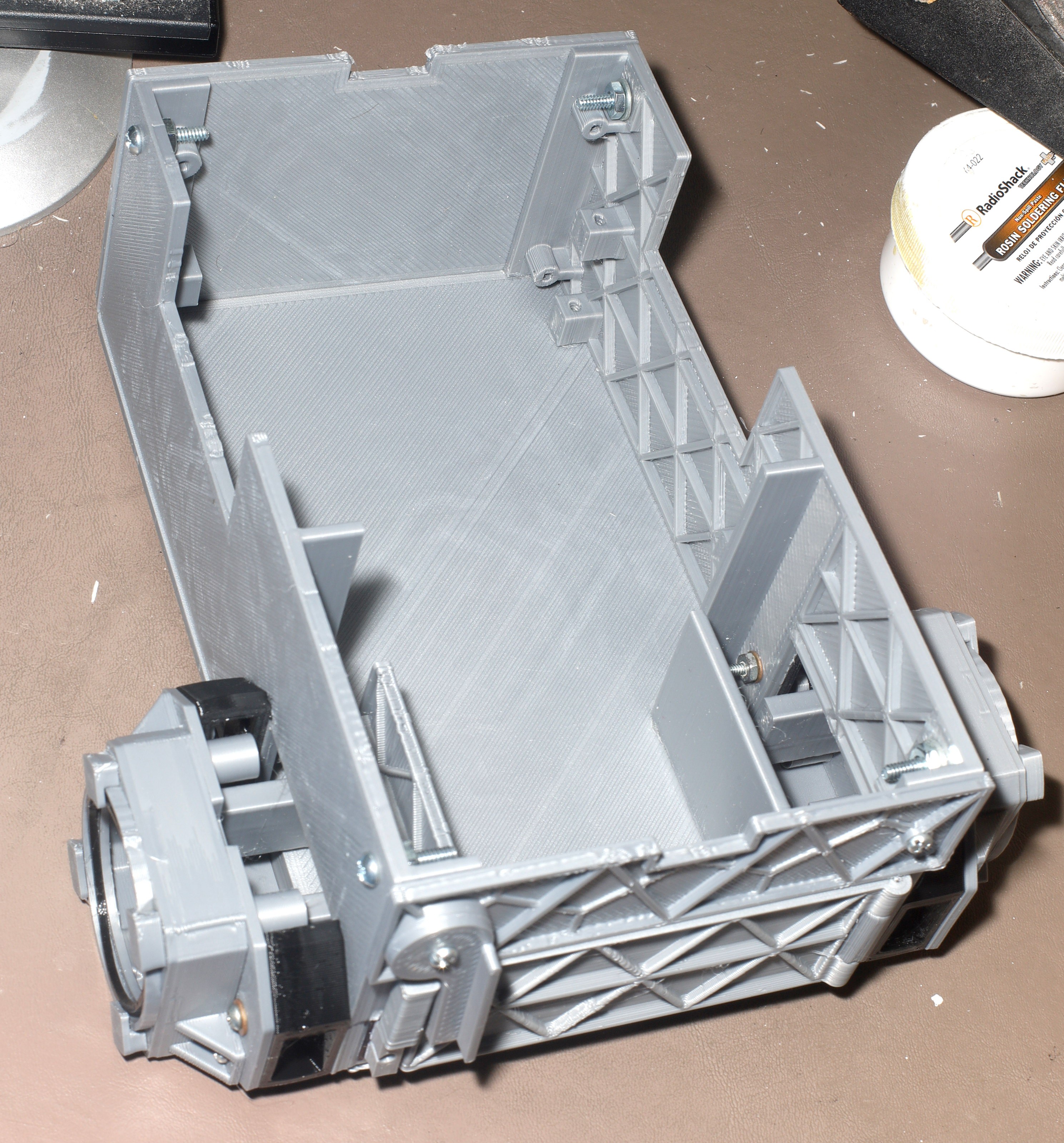
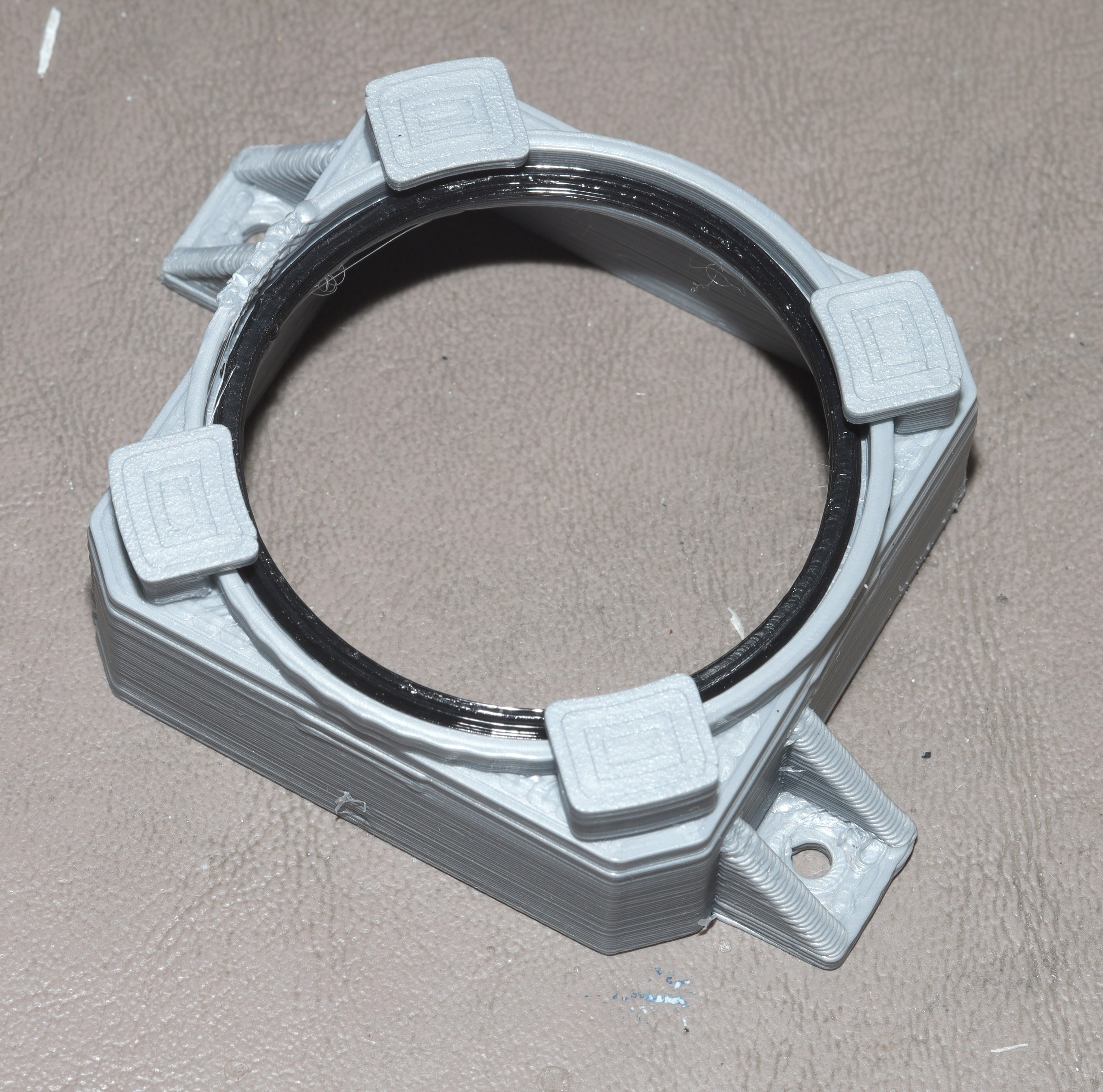
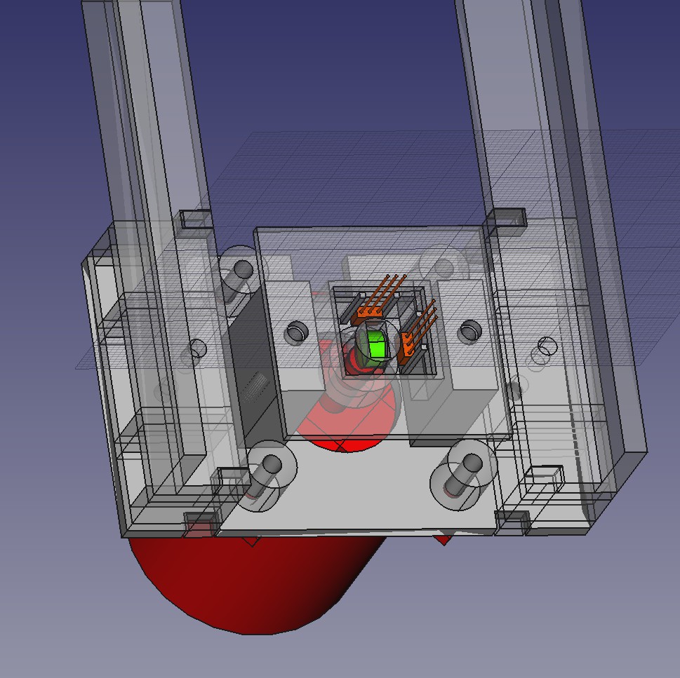
The key was a novel motor shroud with a TPU o-ring that would theoretically keep rocks out.
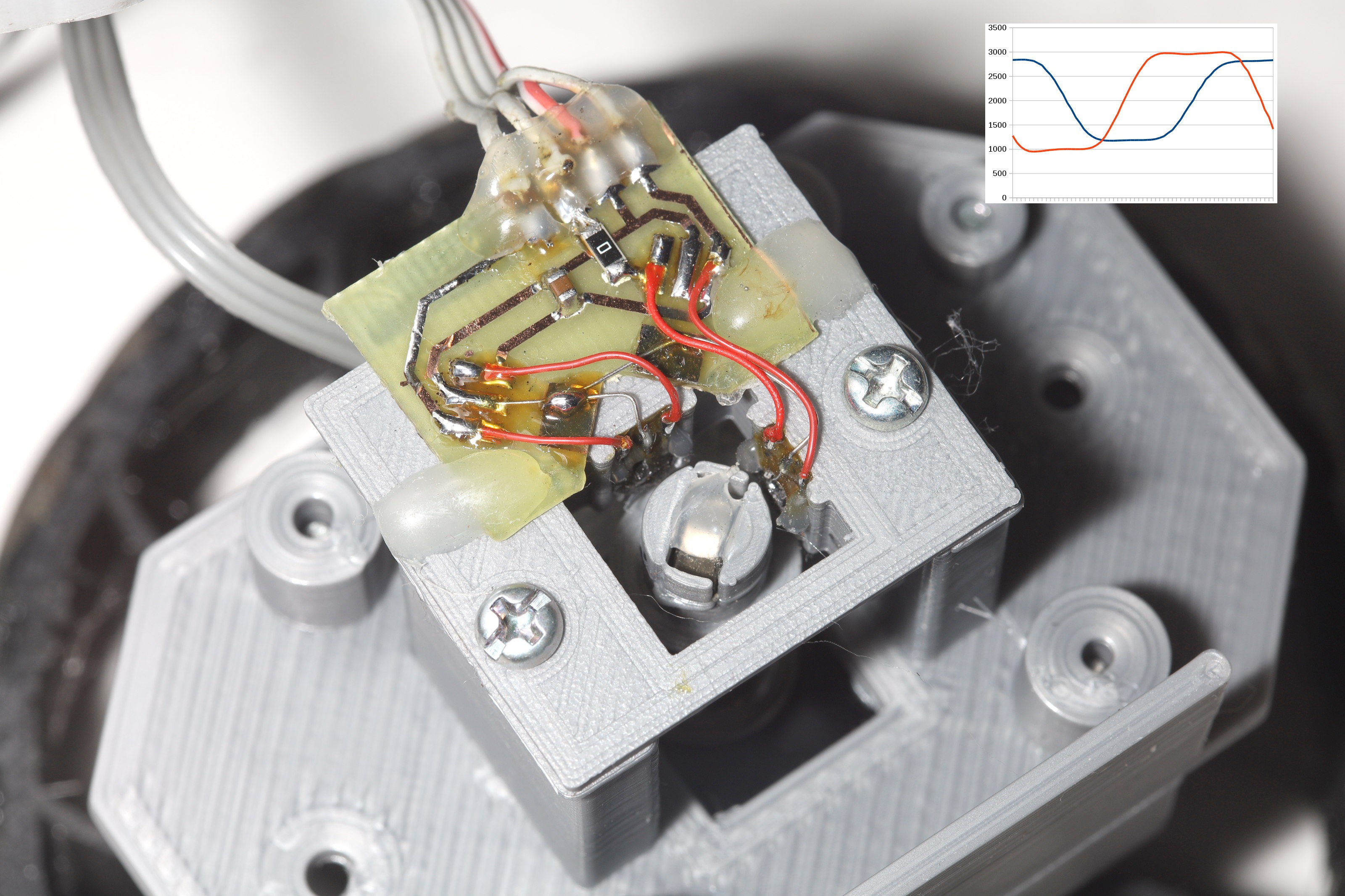
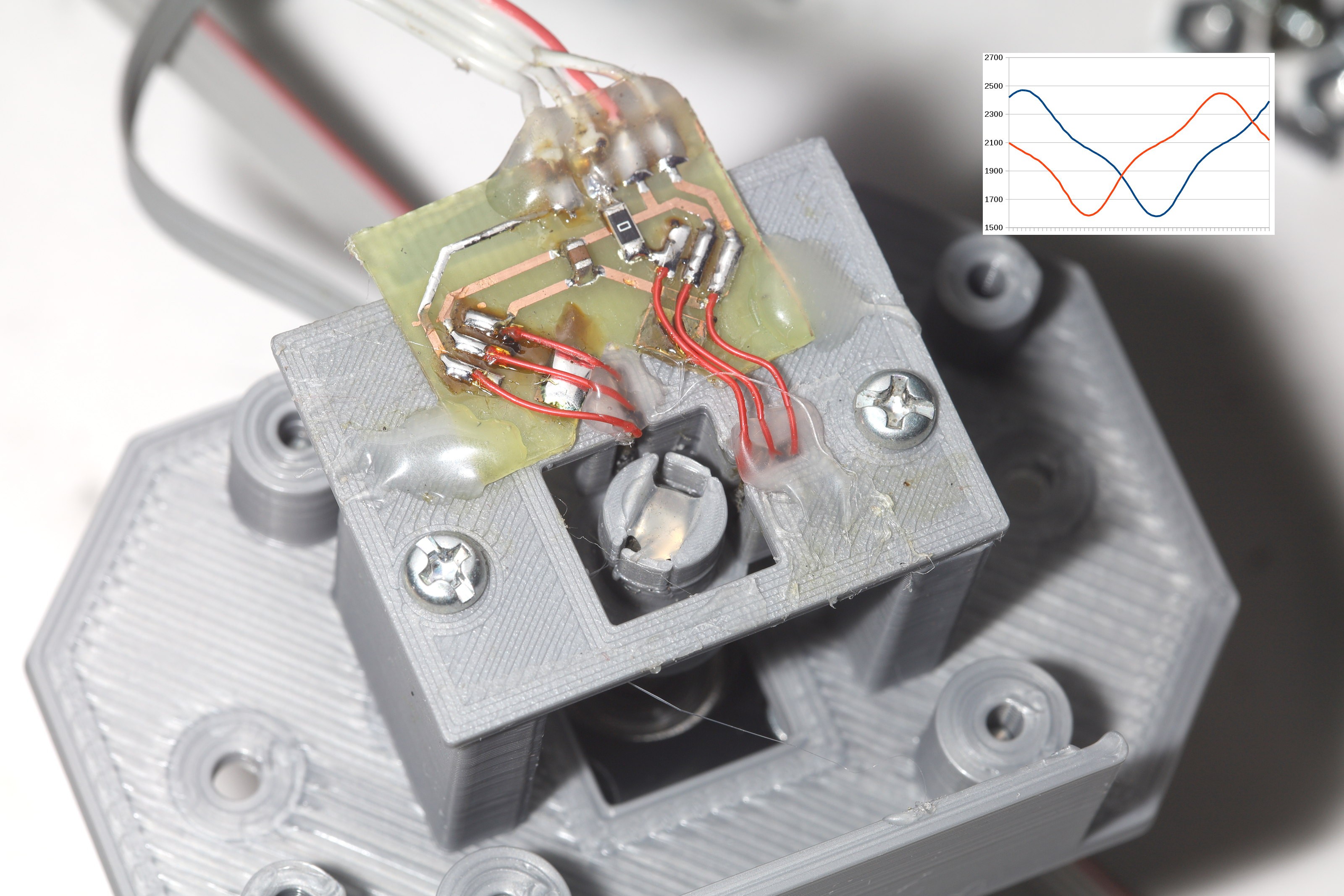
The encoders continued to plague the motors.
![]()
![]()
The hall effect sensors were reoriented, which allowed them to finally sense the full range of motion. They have to point along the circumference rather than radially. The resolver in this configuration is thus the easiest way to detect motor position.
![]()
![]()
![]()
![]()
![]()
The easiest way to cover the H bridges was duct tape.
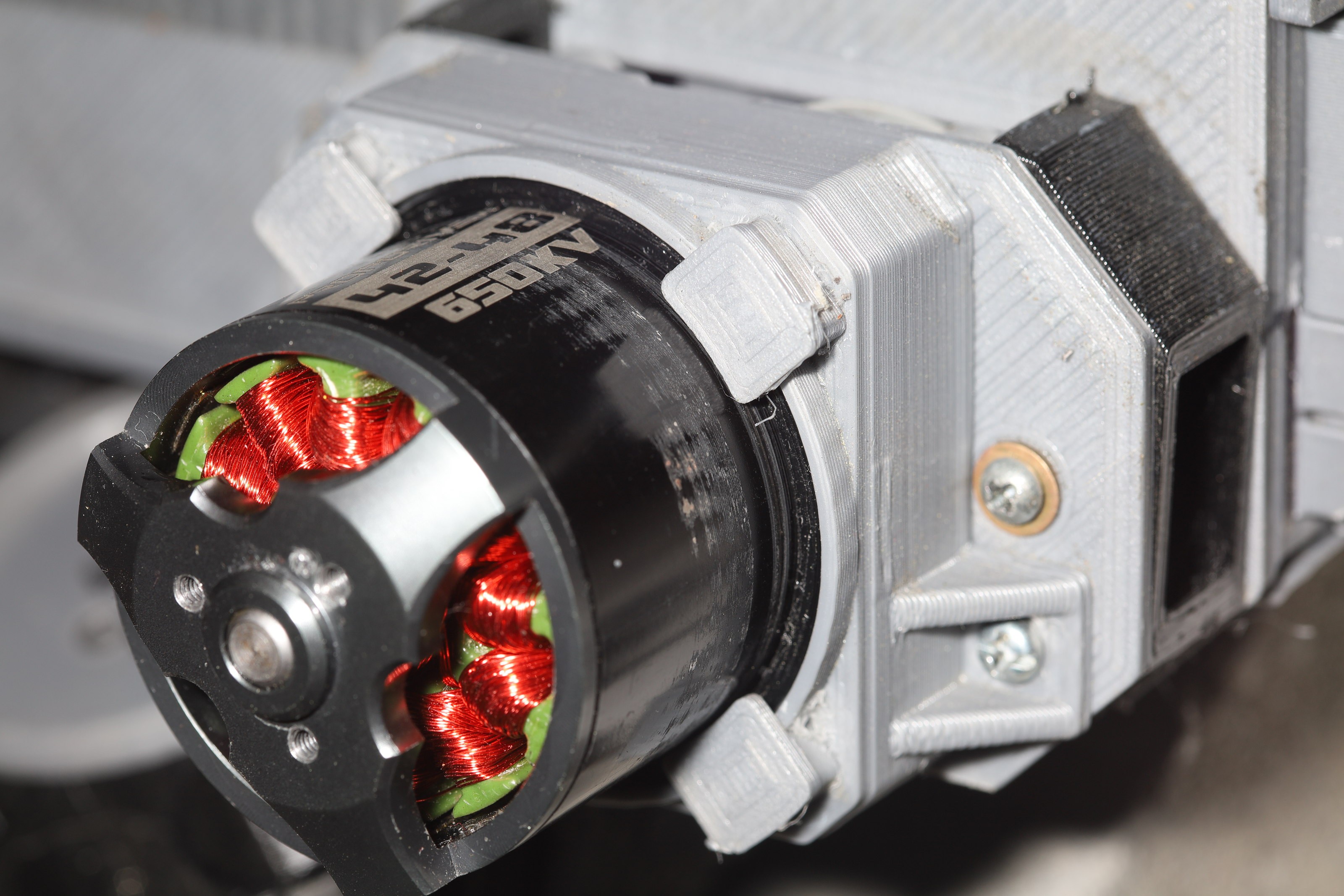
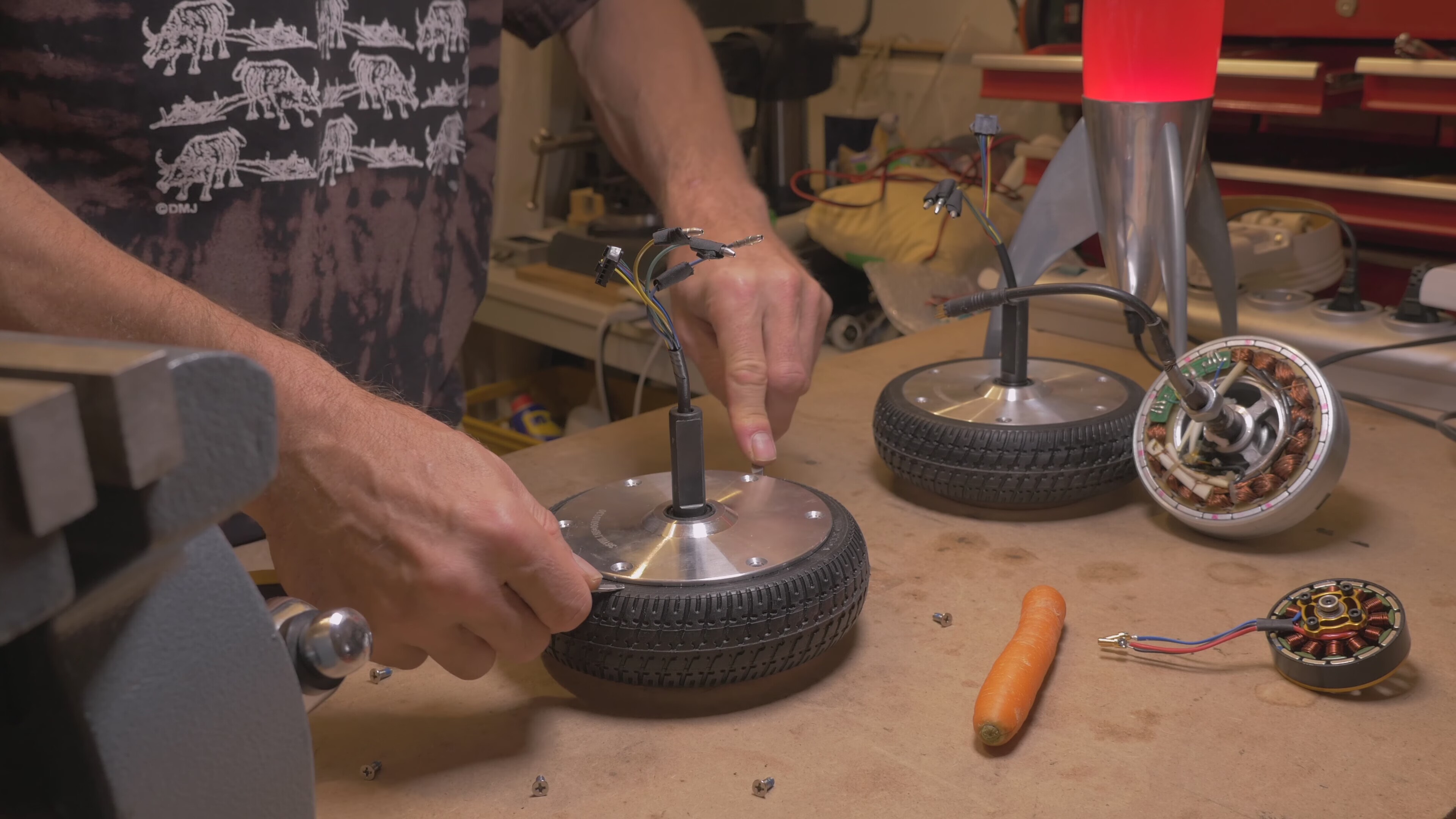
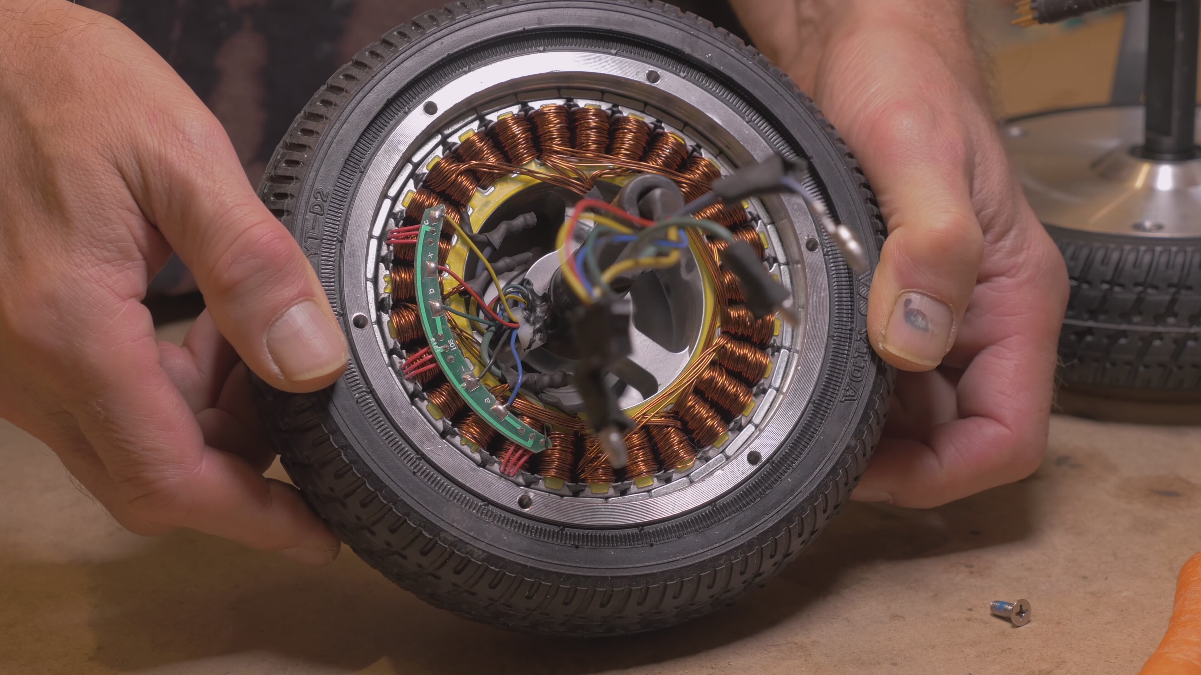
Torque limitations continued to plague the motors. It turns out the cheapest source of large diameter motors for this task is inside hoverboards. They're far cheaper than hobby motors of the same size. They're sealed from rocks. Hoverboards have long ago faded from popularity & their cheap motors might be going away. The motors replacing them are much smaller skateboard motors, with much less torque, at a much higher price.
The media was focused on the batteries in hoverboards, so the public became singularly focused on tearing down just the batteries while ignoring the motors. There are very few teardowns of the motors.
![]()
![]()
These are sadly too big for the truck in mind. They're too big even for a brushless gimbal. It's remarkable how economies of scale during the height of the hoverboard craze made such large motors almost free, while tiny hobby motors are a fortune.
-
New controller charger
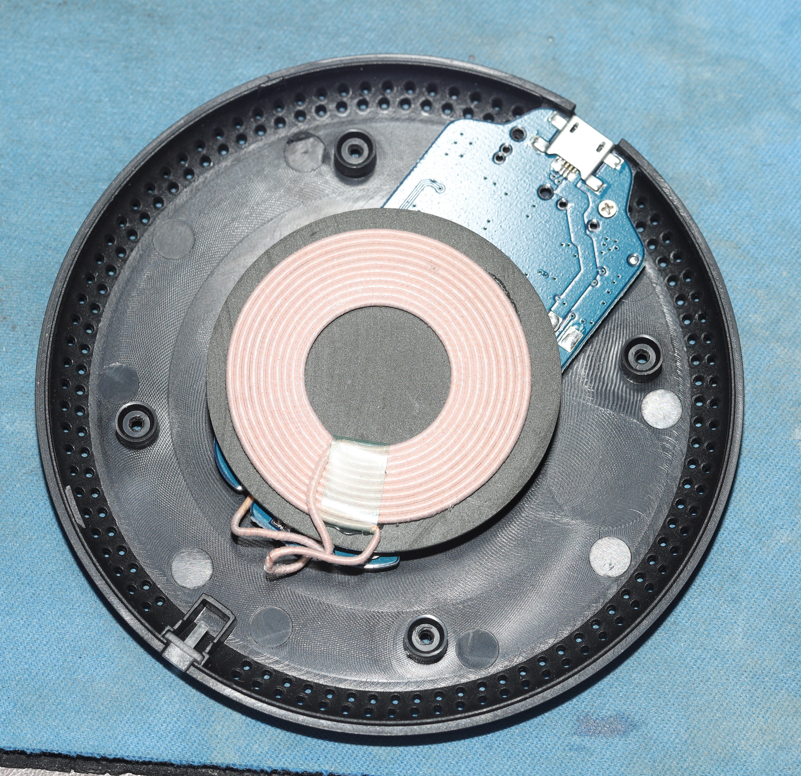
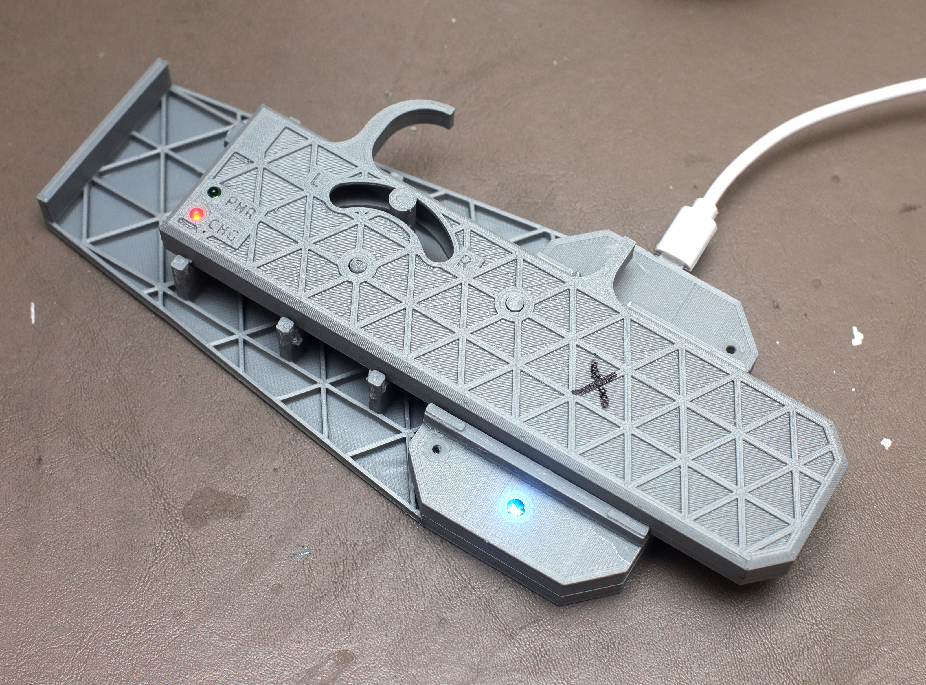
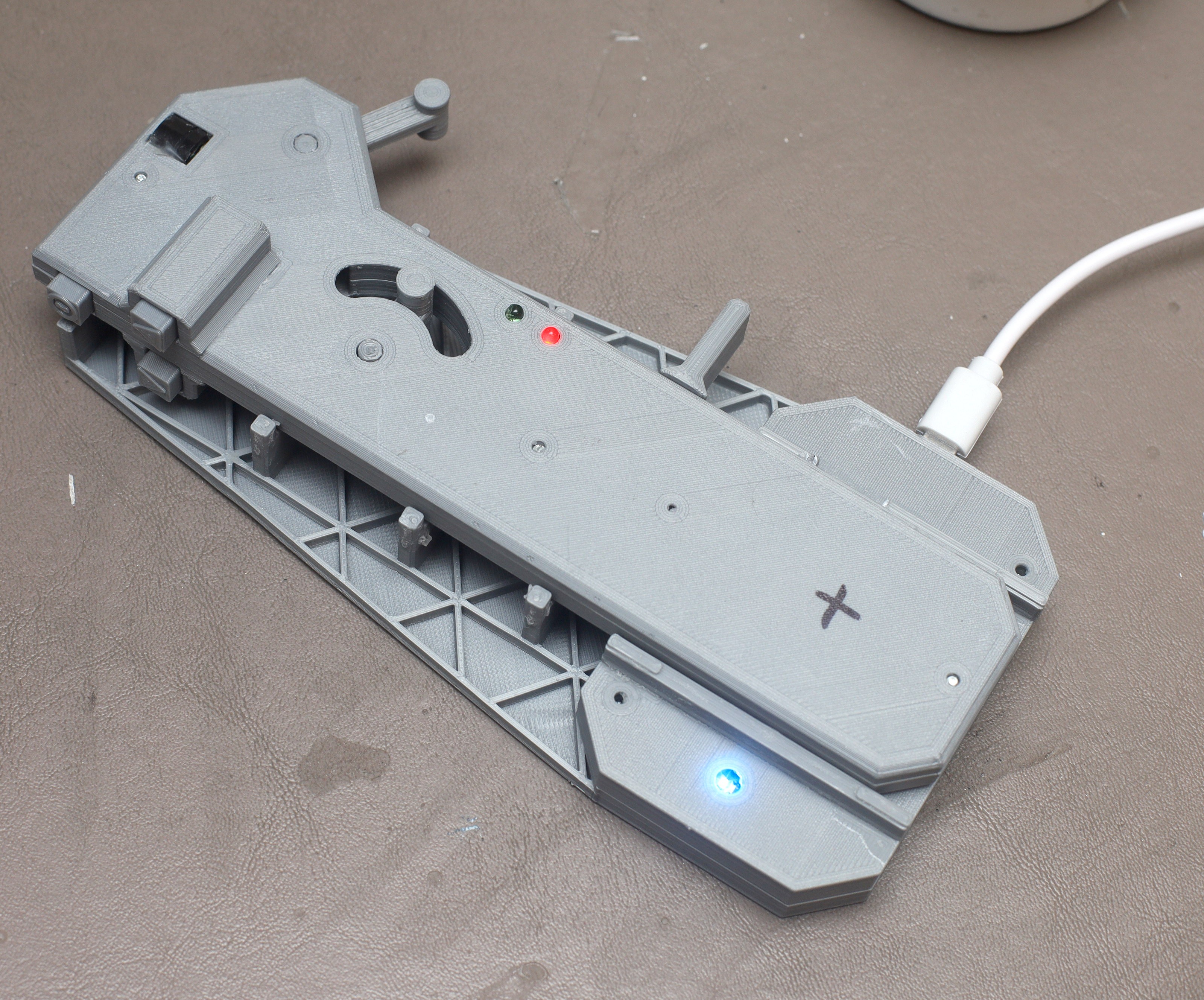
02/10/2021 at 06:19 • 0 commentsThe lion kingdom's 3 year old Qi charger was proving a disaster for charging remote controls. Putting a magnet in any controller would take up a lot of space, so there was no easy way to align them on the charger. Then, the unusually shaped controllers weren't held in position. The decision was made to finally make a new charging enclosure that would fix the controllers in the right position. It's a very loose position, but good enough. The status LED in the charger, once completely covered by the case, is now visible.
Printed it out with the .4mm nozzle & .4mm line width. It has only .8mm thick panels. Called it quits after 2 prototypes.
![]()
![]()
![]()
![]()
![]()
![]()
-
Smaller tires
02/01/2021 at 07:42 • 0 commentsThe lion kingdom printed some smaller 90mm tires to get more climbing speed. Tire designs are getting much softer & quieter, but not improving the traction.
![]()
![]()
![]()
![]()
![]()
![]()
These introduced a shroud to keep rocks out of the motors. These reduced the maximum speed from 10mph to 8mph & didn't materially improve the climbing speed. The other options were higher voltage batteries, expensive. There was more windings of lower wire gauge, not enough room. There was using bigger motors, very expensive & reduces ground clearance.
The cheapest, most configurable option is a boost converter. It's a way to use semiconductors to make a motor pass more current from a lower voltage. The boost converter would allow the motors to be rewound again for higher torque & higher voltage or it could just be used to send more current through the existing windings. The maximum torque is achieved with 70-80 turns of 32AWG, depending on room. This requires over 40V to hit 10mph with a load, according to past notes.
The current winding is 20 turns of 26 AWG. It achieves 10mph with a load, on 12V. The boost converter might require more turns of finer gauge to manage the heating. It reduces range by up to 20% depending on the load.
-
New controls, new tires
01/27/2021 at 06:50 • 0 commentsThe mane problems encountered during the 1st 74 miles were the paw controller's ergonomics, the tires being noisy & too hard, the battery cover coming off, motor encoders slipping out of alignment, lack of torque.
![]()
A pile of 3D printing yielded improved tires & a new paw controller.
![]()
![]()
![]()
![]()
![]()
![]()
![]()
![]()
The new tires were about as compliant as TPU could get. The mane variables are whether to have a tread, how curved they should be, how wide they should be. They got down to $1.50 of material. They were slightly quieter than the 1st tires.
![]()
![]()
![]()
The paw controller was more of a manufacturability upgrade than an ergonomic upgrade. The enclosure was made a single thickness. The new controller is thinner & lighter than the old one. There wasn't enough room to keep the isogrid or any of the markings. The steering lever was shrunk to make it easier to steer while going in reverse. The problem is lions stretch more in their right paws than their left paw so it's never going to be a perfect fit in both paws.
The speed buttons were enabled, opening a new world. Never before was it this easy to adjust the speed. Lions immediately began stepping up the speed for every downhill, taking a lot of time off their runs. Unfortunately, the clamshell tends to separate, creating a lot of variability in the analog readings.
All manual steering or throttle ended up useless. The confuser does a much better job than the lion, so binary steering & binary throttle were put back, using the analog readings to have 2 steps for steering.
-
The era of direct drive begins
01/16/2021 at 03:42 • 0 commentsPrototype 2 died after .5 miles. The motor drivers overheated. The motor encoders slipped out of alignment. The manual steering proved difficult.
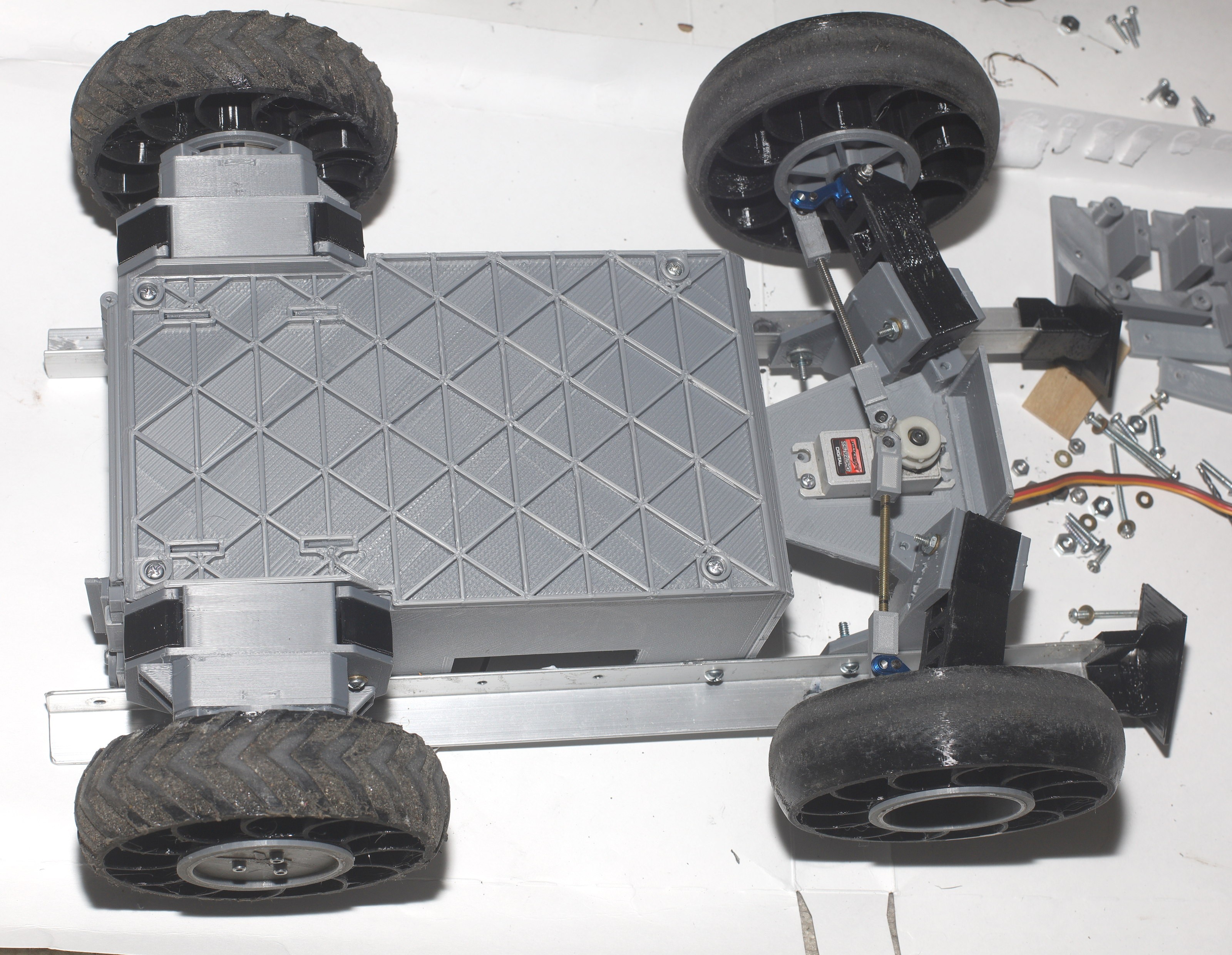
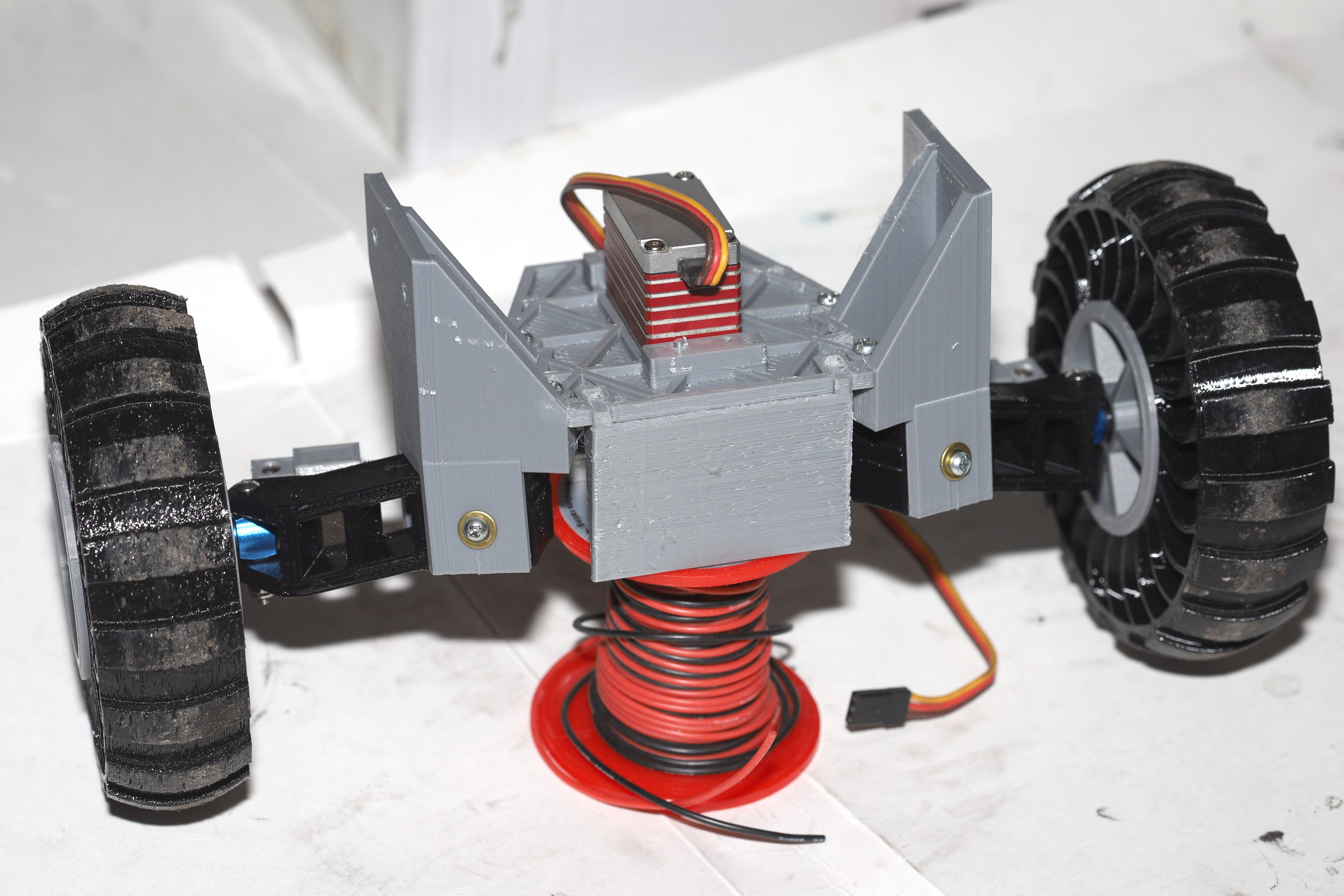
A nearly complete redesign of prototype 2 yielded the 1st prototype to go 6.4 miles.
![]()
![]()
![]()
The chassis was widened 20mm. The steering section was redesigned a 3rd time.
![]()
![]()
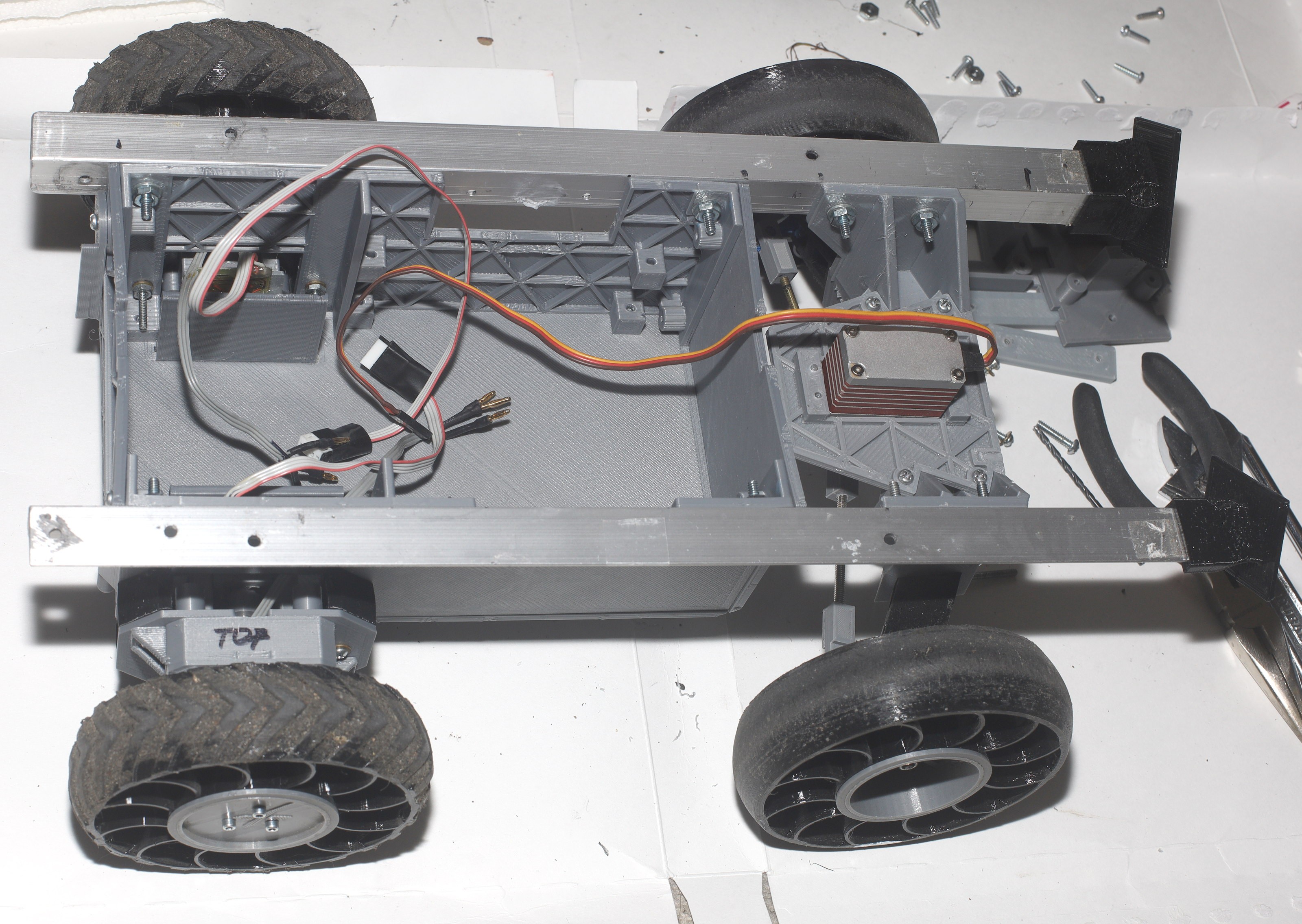
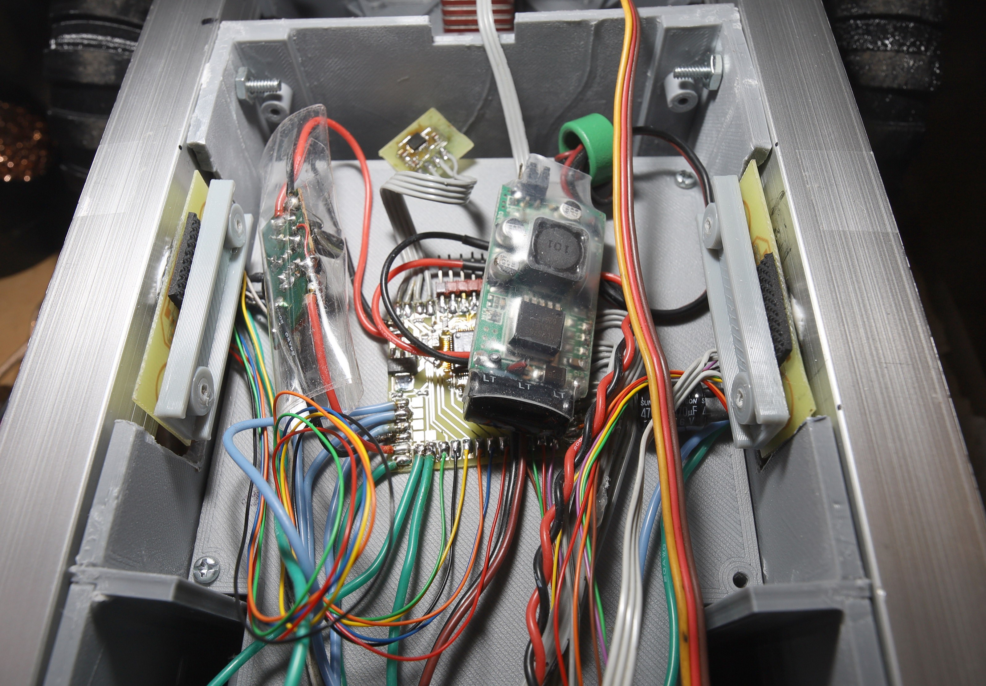
To cool the motor drivers, the L6234's were soldered upside down & bolted on the angle aluminum. This entailed soldering 22 flying leads to breakout boards, but it worked.
There was a long drawn attempt to hack an ESC to be a directly controlled H-bridge, but a stock ESC doesn't have enough serial port bandwidth to be updated at the required 16khz.![]()
![]()
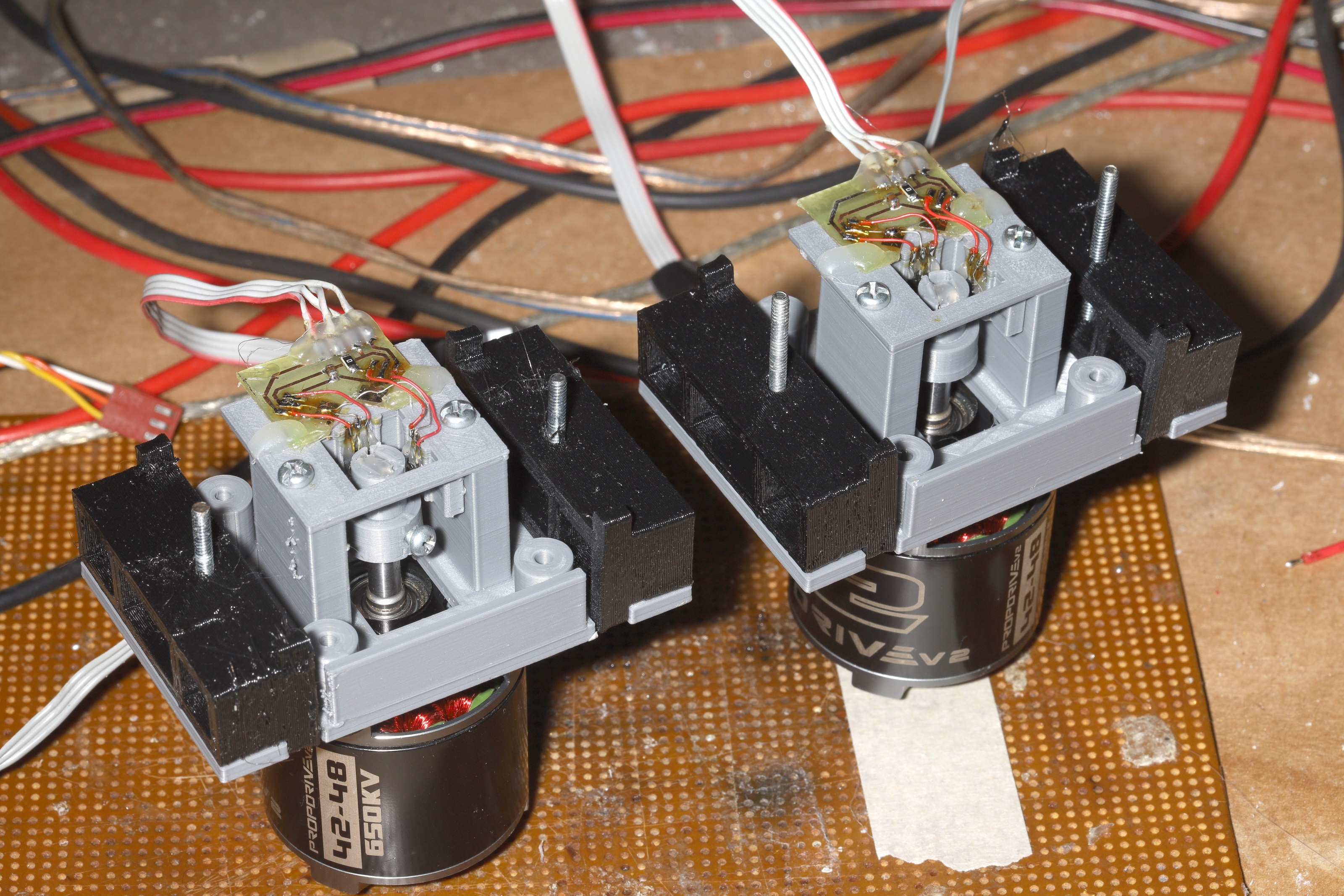
The traction module was redesigned for modularity.
![]()
![]()
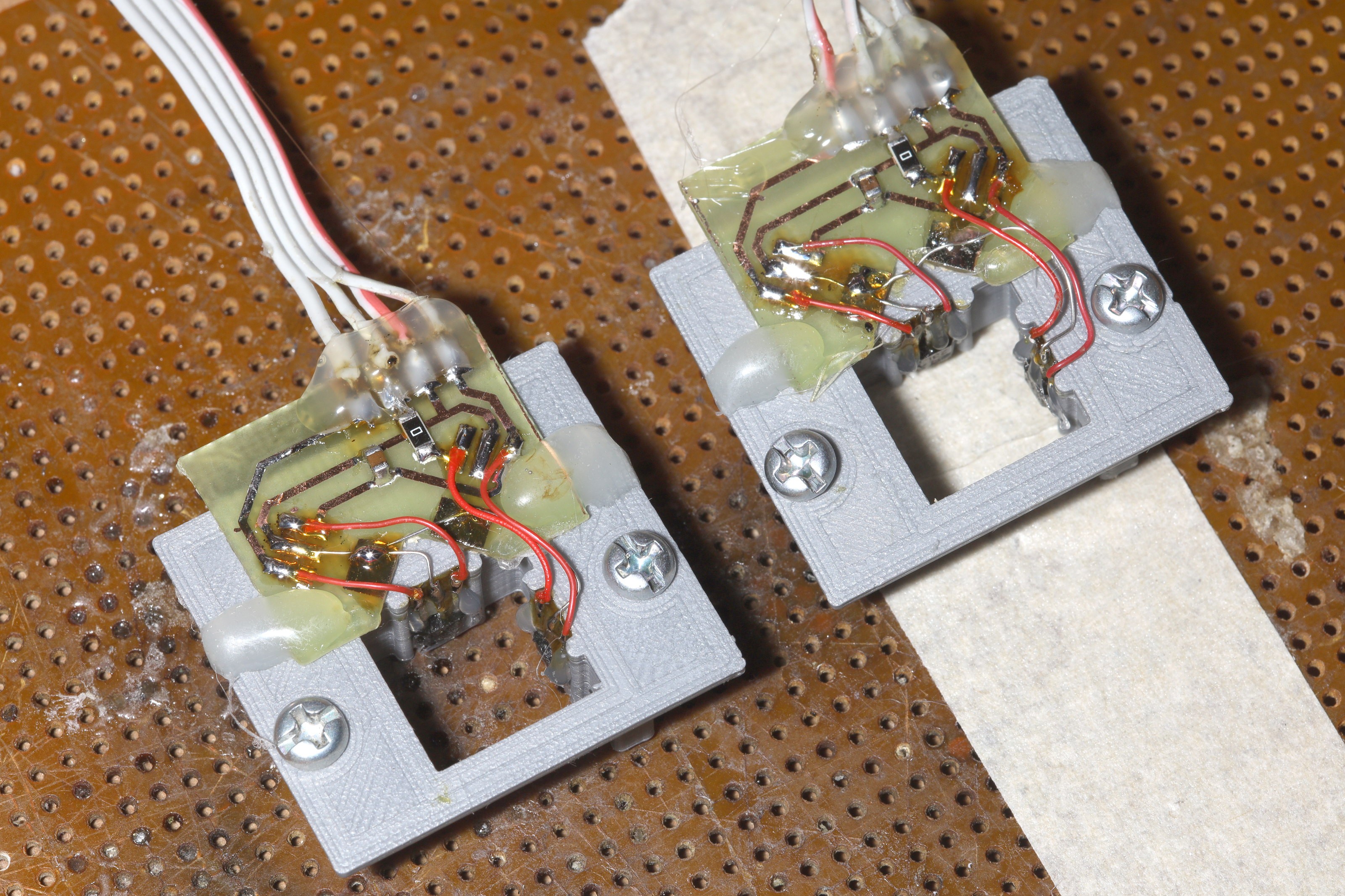
The motor encoder was redesigned to use 1 magnet & 2 hall effect sensors.
![]()
![]()
![]()
The motor was made more modular, but it has a long way to go.
With no payload, over hills & bumps, with minimal stops, power consumption was a whopping 175mAh/mile. It could go over 20 miles without a payload, on a single battery. It could also go 10 miles on a much lighter battery. The low power consumption was manely from the hard tires & very little contact patch. Less benefit was from being direct drive, lions believe.
The mane limitation was now the paw controller. The controls need to be spaced out 10mm in every direction & it needs to be bigger.