 TheMixedSignal
-
1Fabrication
- 3d Print the Motor bracket, Linear stage brackets, Carriage top and Bottom, and Line-holding/guide pieces. NOTE: Use opaque, dark material for this (i.e. black PLA, and NOT the semi-clear material I have here). The flags for the limit switch will require tape if you don't use an opaque material.
- Grind or Cut off a piece of the acme threaded rod/lead screw to be about 105mm long.
- Using a laser cutter, cut out the dxf pattern on 1/4" (or thicker) acrylic plate.
Note: You can also print this out onto several sheets of 8 1/2 x 11paper, arrange and tape to the acrylic, and then hand-drill, but this might be time consuming. The large holes are meant for a 1/4-20 tap, and the small holes are meant for an M2.5 Thru hole. (Though they could be used for an M2.5 tap, depending on what type of hex standoff you have). If drilling by hand, verify that the drill bits used are the correct size.
-
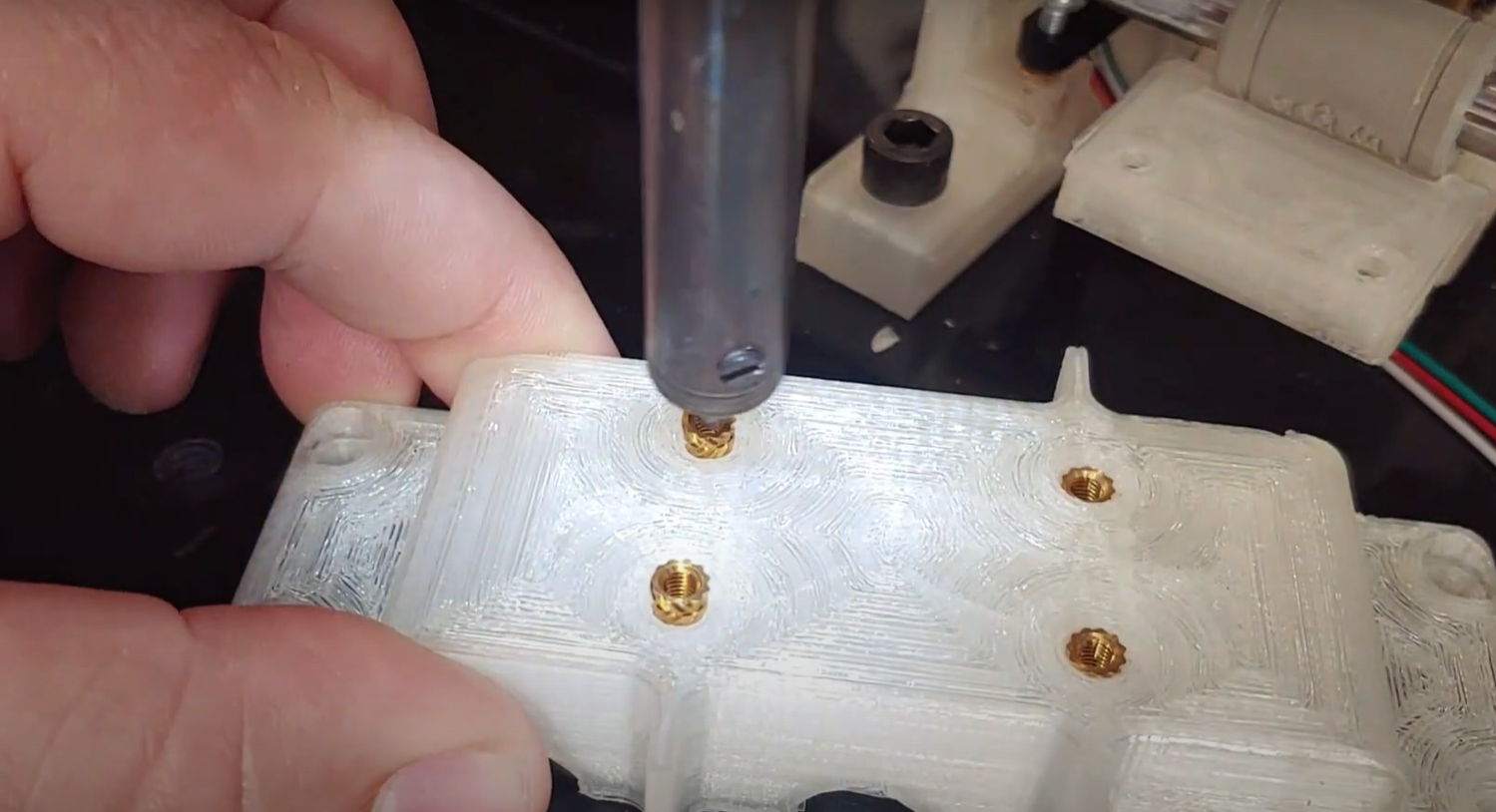
2Placing the Heated Inserts
Using a soldering iron, press the M3 heated inserts into the top of the carriage, and into the Linear Stage Bracket (where the optical sensor will be mounted)
![]()
-
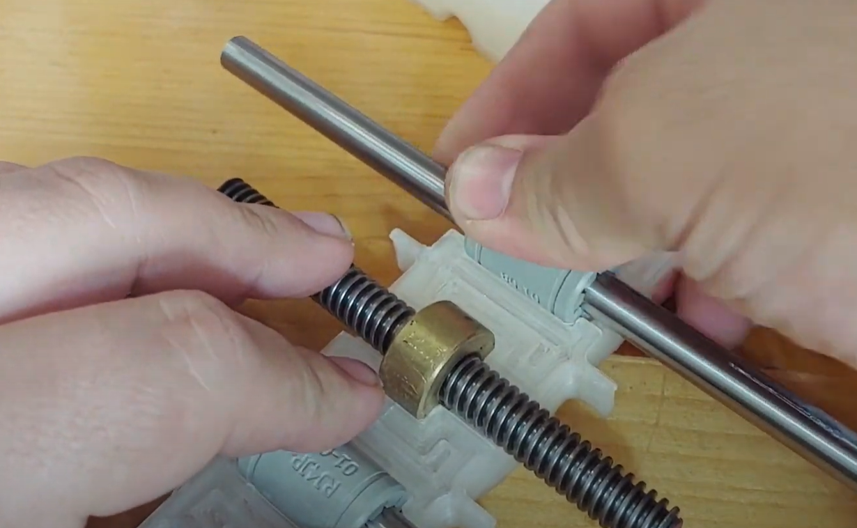
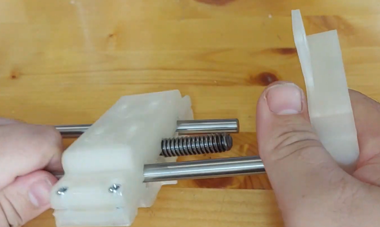
3Assemble Carriage
- Slide 2 LM8UU linear bearings onto the 8mmx150mm rods.
- Partially thread the brass nut onto the lead screw
- Press all three into the carriage bottom (this was a tight fit for me w/ my printer - you may need to tweak the design a bit)
- Attach the carriage top using M3 screws w/ Hex Nuts.
![]()
![]()
-
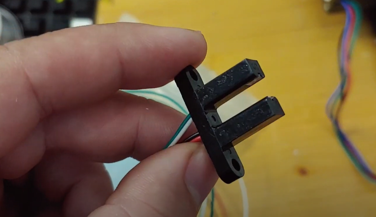
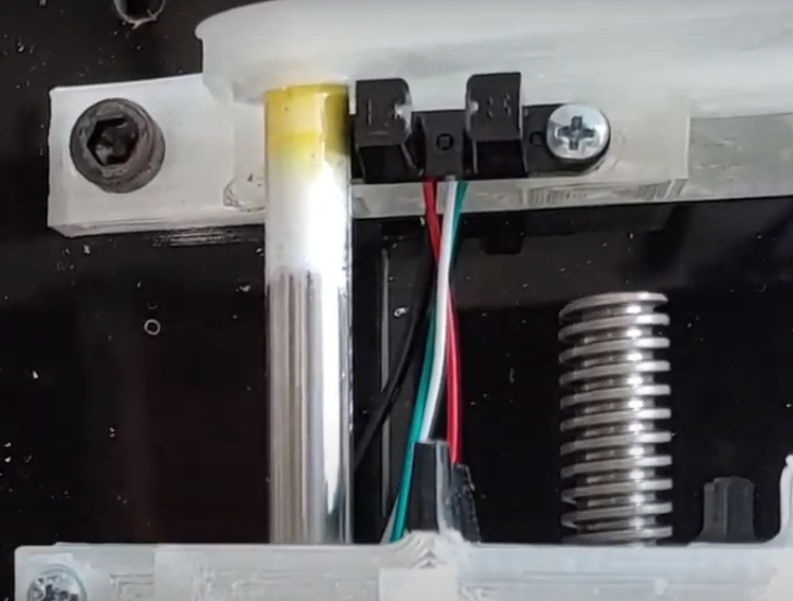
4Assemble Linear Stage
-Attach Optical Sensor/Limit Switch to linear rail bracket
![]()
![]()
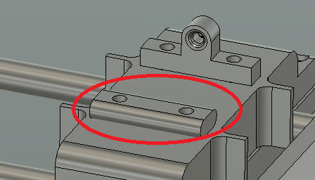
- Press the 8mm rods into the linear stage brackets
![]()
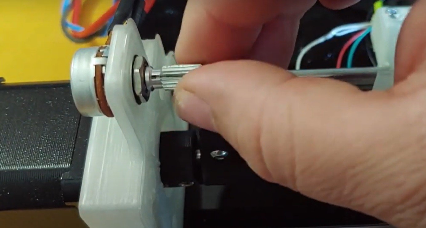
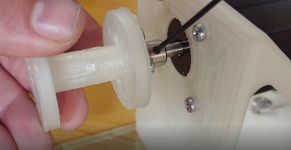
- Attach shaft coupling to the motor, and mount motor onto the bracket
![]()
- Attach potentiometer and solder wires to its three contacts
![]()
-
5Attach Subassemblies to Plate
- Attach the Arduino Uno, linear stage subassembly, and the spindle mount to the laser cut plate.
-
6Configure and Attach the CNC Shield
- The CNC Shield axes used for this project are X and Y.
- Set all of the microstepping mode jumpers (microstepping = 1/16) for both X and Y drivers
- Attach the shield onto the Arduino
- Attach the stepper drivers the correct axes locations on the shield (verify the orientation is correct or you'll fry things on power up).
-
7Wire up Optical Sensor and Potentiometer
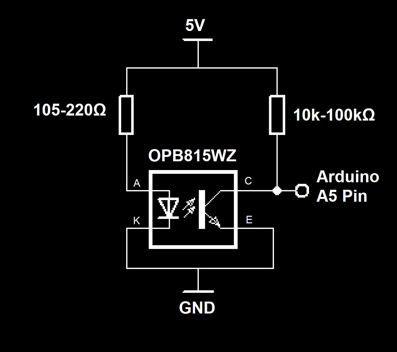
- Connect the optical sensor anode pin to a 105-220Ω resistor. The goal here is to set the current for the IR LED to somewhere in the 15-30mA range.
- Then connect the Collector pin to a 10k-100kΩ Resistor. The optical flag should produce a big change in signal here when an opaque material passes through the slot, so there's a bit of flexibility here in value.
- The node that connects the collector pin to the resistor will go to the A5 pin of the Arduino. These can be soldered directly onto the CNC shield.
- Connect the common node of the Anode and Collector Resistors and solder that to 5V pin on the Arduino
- Connect the Emitter and Cathode Pins to a GND pin on the Arduino
![]()
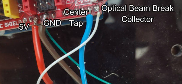
- Solder a wire from the top and bottom pot contacts to 5V and GND respectively.
- Solder a wire from the center tap to the A4 Pin
![]()
-
8Program the Arduino
Upload the sketch in this project onto the Arduino. Depending on what your pickup height and attachment situation is, you'll need to adjust these two definitions:
#define MAX_XPOS 64000
#define MIN_XPOS 15000
Note: this firmware also assumes microstepping has been configured correctly, and that the system has a working limit sensor. If either of these are not done correctly, the linear stage could destroy itself.
-
9Test the system out!
- First, get a feel for the spindle. Because it's a stepper motor, there will be some unhelpful mechanical resonances (the microstepping helps with this a bit), but overall it needs to be gradually accelerated to its maximum speed. Get a feel for how that works before attempting to wind anything.
- Also, it'll take some fine tuning of the min and max locations in code to get this fully optimized for whatever pickup you're winding. I recommend doing a few passes with the spindle off (potentiometer turned all the way in the off position, below the "threshold" where the motor starts) to get a rough feel for where things will be, and then make your first adjustment. Follow this up with a "slow run", where potentiometer is turned part way on, and the spindle is running very slowly. Adjust parameters again.Note: I used a custom 3d printed single-pole bobbin (for an organ tonewheel) and some 40AWG enamel-coated wire.
![]()
- To start running line, first feed it through the feed loop:
![]()
Then attach the clamp bracket to apply some tension to the line. Tear off a small piece of paper towel or cotton to wrap the line in before clamping. This should help prevent it from snagging, and apply a more consistent pressure. Don't clamp down too tight or you'll prevent winding.
![]()
Just make sure your spool of wire is free to spin freely somewhere, and you should be about ready to start winding!
Automated Pickup Winder
This project is an automated winder for making custom pickups for a guitar or a tonewheel organ


Discussions
Become a Hackaday.io Member
Create an account to leave a comment. Already have an account? Log In.