Clyde Shaffer
-
V3 prototype assembled and working!
06/23/2021 at 02:02 • 0 commentsGot the boards in on Friday and spent the weekend soldering this baby over a few sessions.
Originally I anticipated spending the week in "integration hell", but ultimately I only had to add one bodge wire after realizing that I gave a certain net the name !RE2 "Read Enable 2" on one sheet and !OE2 "Output Enable 2" on another sheet. As a result the CPU had been able to write to Graphics RAM but not *read* it; which is necessary for the Inflate algorithm as well as programs simply using it as extra general-purpose memory.
For now I'm powering it with my bench supply through two wires soldered on at the back. I've designed and ordered a board that can solder on in place of these wires, based on an LM2575 switching regulator and its reference schematic in the datasheet.
After that the next step is to design and print a suitable case. The "tank" theme will work into that but I'm still deciding how subtle.
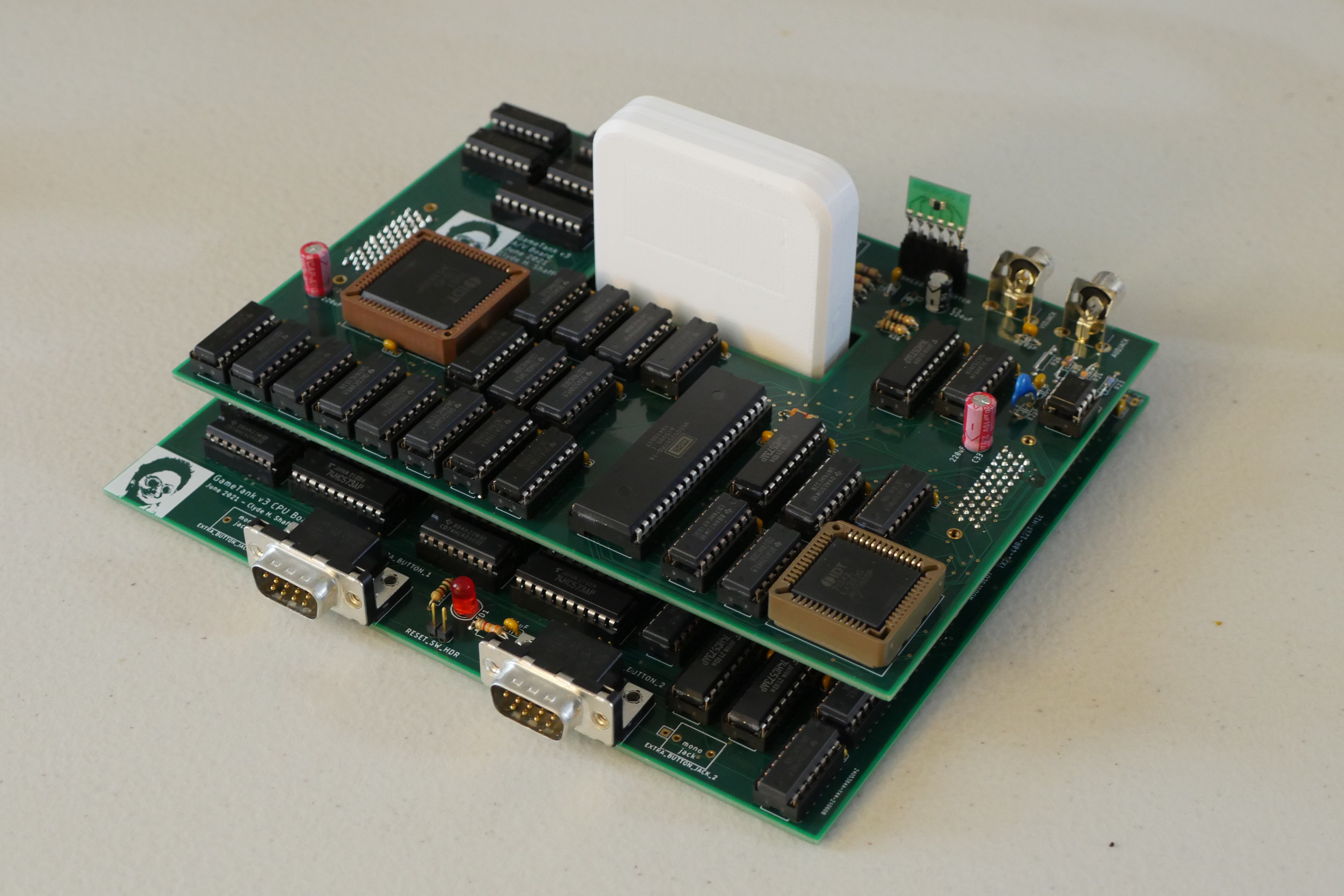
The board stack already looks kind of cool, so the enclosure will have to be cool enough to compete if it's going to cover that view.![]()
It's a bit of a rush to hold this thing. With almost a hundred ICs it has a certain heft that feels about right for something that took me three years to make. -
Form-Factor Prototype
06/11/2021 at 23:47 • 0 comments![]()
After fixing the last blitter bug, I sat down and combined the four board designs of the V2 prototype into a surprisingly compact two-board stack. Combined PCB footprint is 7"x6" and hardly an inch and a half high.
I wondered at first if I'd have to go up to six layers but it ended up working out in just four. The autorouter seemed to have an easier time with the bottom board than the top board, strangely enough. Maybe it was because of the irregular shape.
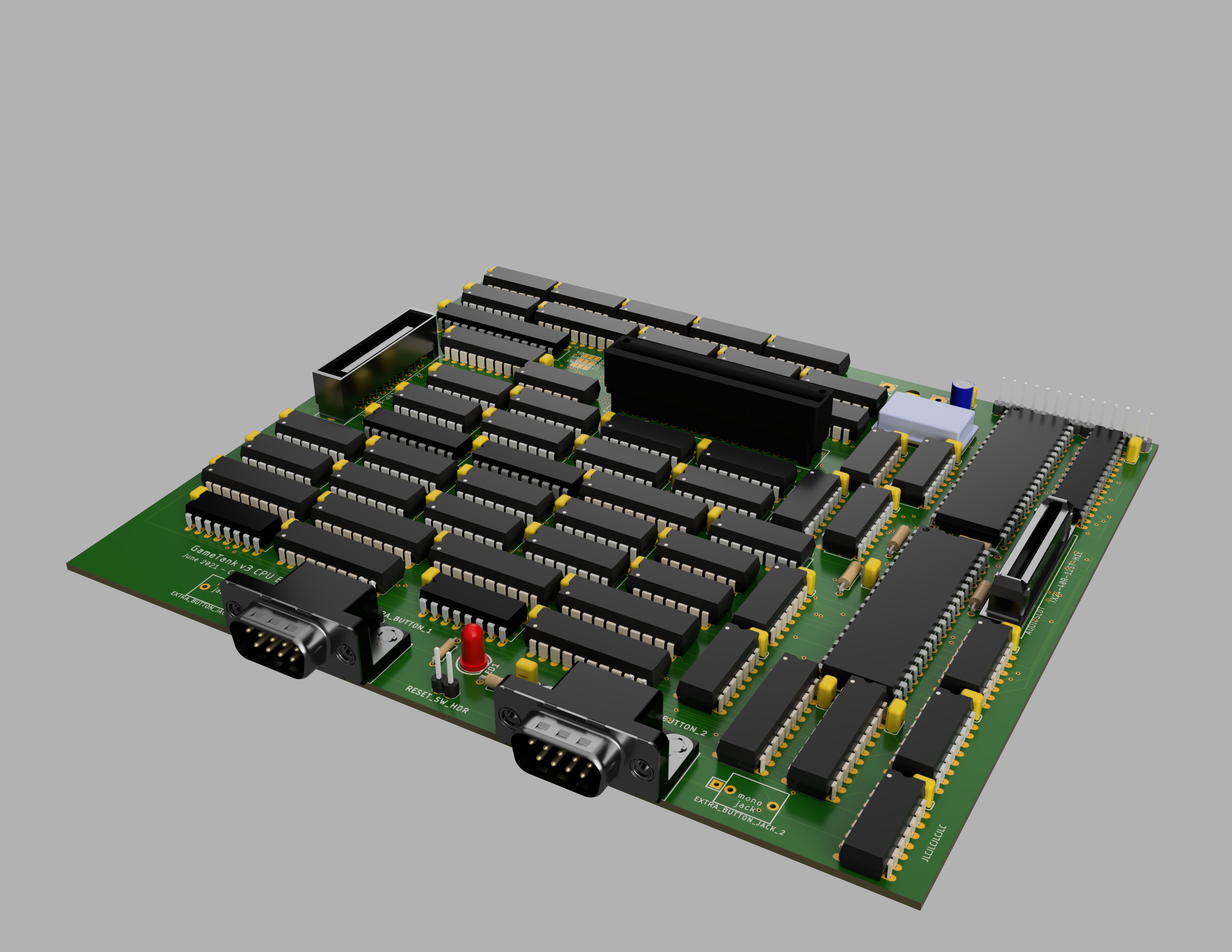
So that I could start designing the case, I exported the boards to Fusion360 and generated these high-res renderings. (Well, I suppose the high-res wasn't necessary for case design but it does make for nice web content!)---------- more ----------![]()
The bottom board combines the blitter, address decoding, CPU, input ports, cartridge port, and VIA.
The keyboard switches used for Reset and two extra input buttons have been replaced with headers, to connect to case-mounted switches. I've also left a footprint open in case I wanted to use a 3.5mm mono jack for the extra input buttons. This would, for instance, support connecting to certain exercise bikes. I think that would be kind of hilarious.![]() The top board holds the composite video circuit on one side and the audio coprocessor on the other. So I call it the "Signals Board".
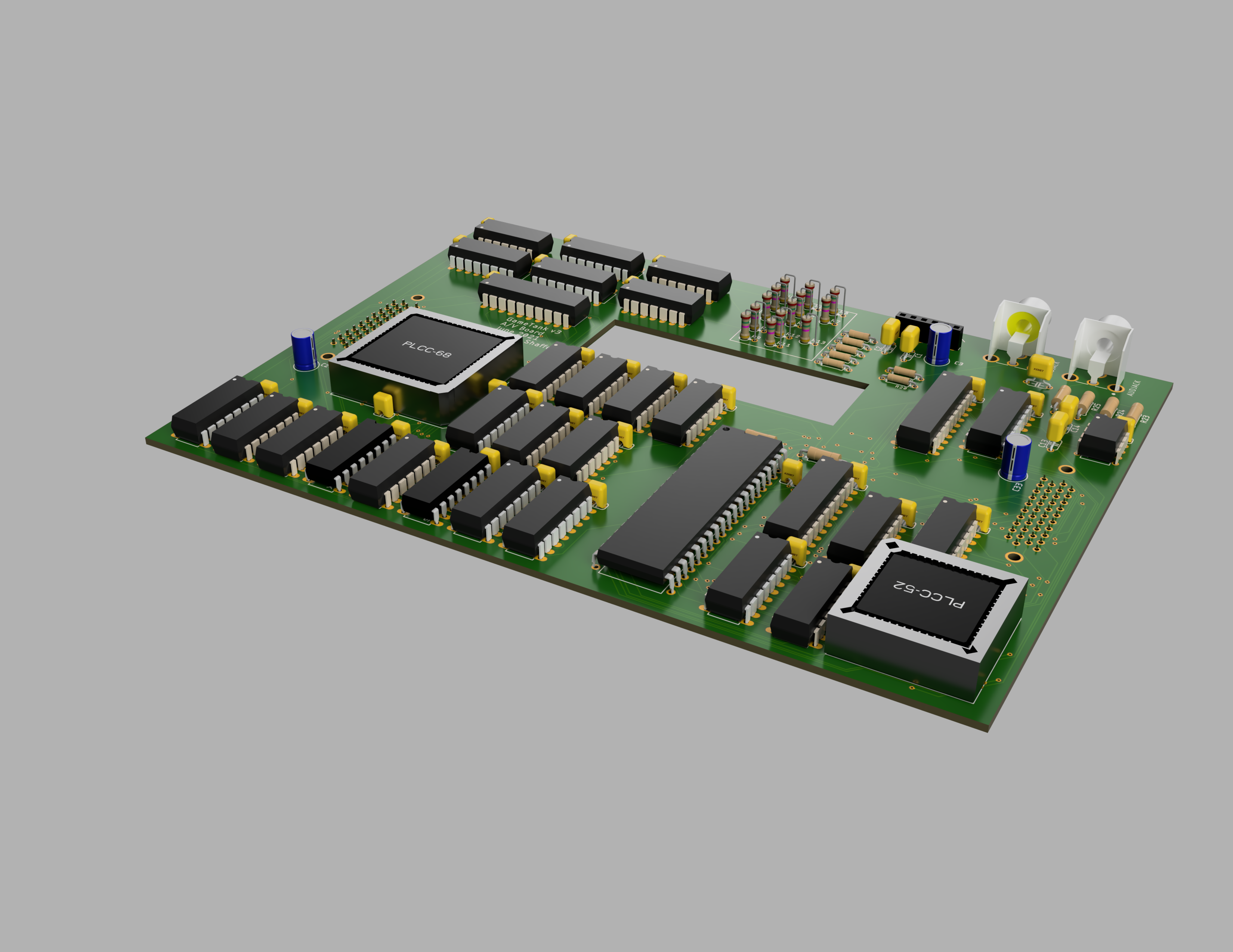
The top board holds the composite video circuit on one side and the audio coprocessor on the other. So I call it the "Signals Board".
It occurs to me at time of writing that I have no idea whether the big hole in the ground and power planes will be an issue. From what I've heard there is an unlimited number of ways to accidentally create an antenna. So hopefully this antenna isn't resonant at any frequencies I care about.In the corner near the RCA connectors, I put a header that exposes twelve otherwise-unused VIA pins. Besides eventual expansion hardware, this is handy for debugging and profiling. I've also elected on this version to remove the existing linear regulator and instead leave a place to solder in a power module that I'll design later. This could either stick out the back a little, or go underneath the lower board. Initial testing could be easily done with a bench power supply, or I could just solder in a barrel connector and use a wall wart that already outputs 5V. The reason I switched from the regulator is mainly that it got very hot, even with a heat sink attached. I'd like to switch to a switched regulator instead, but still have some reading ahead of me to comfortably understand how to use one in a design.
I'll post another log after I have the boards in hand and soldered, hopefully working well! -
Bad Apple Demo on GameTank
02/27/2021 at 17:53 • 0 commentsAbout a month and a half ago over a weekend, I implemented a Bad Apple demo that ran on the GameTank emulator. Since then I have been hammering out hardware glitches highlighted by the demo in order to get it into a recordable state. This turned into a deep dive into some problems that have been plaguing the system for a long time. Now that they're patched I feel a lot more optimistic about assembling a GameTank Version 3 within 2021, which will be arranged in a proper game console form factor that can fit on the TV stand next to a Genesis or a SNES!
In particular, the video signal generator had a timing glitch whereby pixels in certain locations would cast a "shadow" onto the center column of the screen. This has been noticeable for a while, but given the high contrast of the Bad Apple music video it was a glaring flaw.
Additionally I've respun the blitter board one more time to use 74HC163 counters instead of 74HC191 that I switched to, in order to try adding a sprite flipping feature. The asynchronous reset of the 74HC191 is unwieldy with such tight timing, so instead I'm using a pair of inverting/noninverting buffer chips that can flip the G.RAM coordinate and achieve the same sprite flipping effect.Not included in the video is a critical fix to the motherboard's generation of read/write pulses. It doesn't make much of a difference in the Bad Apple demo fortunately, but it does mess up graphical operations such as rendering tilemaps in Cubicle Knight. The idea was that ANDing the 3.5MHz and 7MHz clocks would produce a 3.5MHz clock with a shortened positive pulse, but due to a misalignment it would be followed by a brief additional pulse every clock cycle. An adapter board is on its way that will let me cleanly replace the AND gate with a D-type Flip Flop that will produce the correct pulse despite the clock phase error.
The Bad Apple demo itself crams the video frames into 1.2MB using Run-Length Encoding, with each frame being 128x96 and the framerate set to 15/second. The music engine from an earlier post returns and operates in lock-step with the video frames ensuring synchronicity. -
2MB Flash Cartridges Finally Fully Functional!
01/31/2021 at 20:23 • 0 commentsUp until recently the only program storage media I had physically prototyped was the 8KB EEPROM cartridges. These were pretty easy to design and assemble, since all the had to do was adapt the pins of a 28C64 to the cartridge slot. The data was say to address and access since fit well within the memory map of the system.
However, while developing more content-heavy demos such as Cubicle Knight I found myself bumping hard into this memory limit. Already I had compressed the sprite sheet, tilemaps, and music with zlib but could basically only fit one level in the game. I also now had to deal with the ROM space requirements of the new soundcard, which would need a program loaded into it before it could be of use.
I had already reserved the upper half of the memory map for hardware residing in the cartridge port, and there are certainly EEPROM chips that can fit into this address space. An AT28C256 for instance would fill the 32KB and have plenty of room for game content. They're a bit more expensive though, and a mere 4x memory growth would be somewhat underwhelming.
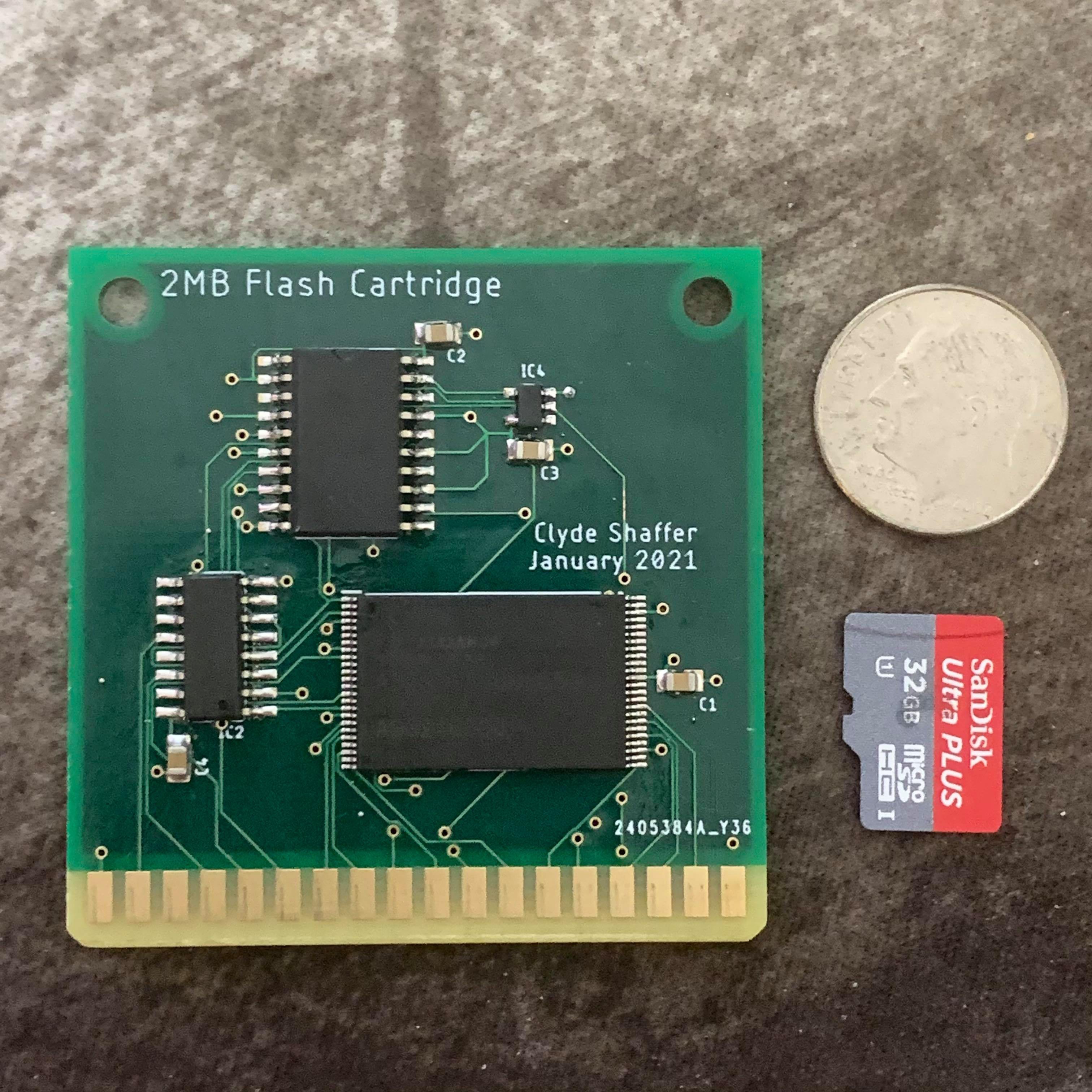
So when I found a flash memory chip on Mouser with a parallel interface and 2 megabytes of space I figured I'd give it a try!![]()
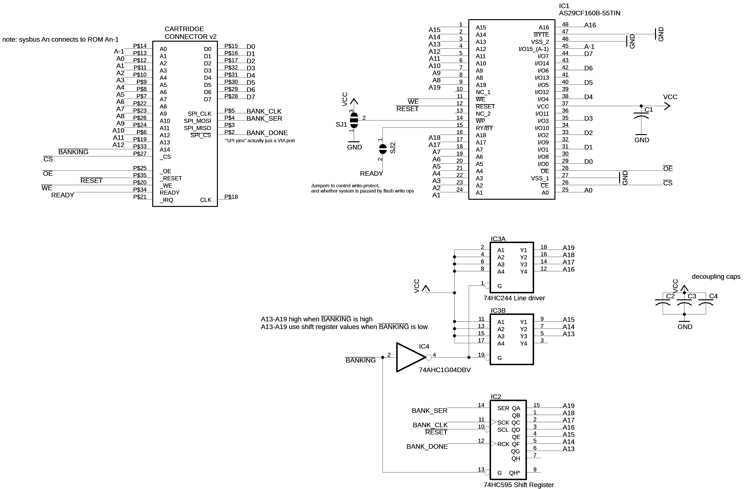
Having already saved the cartridge form factor in my Eagle library, I was able to quickly sketch up a design for a 2MB flash cartridge. The flash chip is a M29F160 (or it's Alliance counterpart AS29CF160), which is a NOR flash that defaults to a simple read mode for an 8 or 16 bit bus, selected by a "byte/word" pin level. In the byte mode the chip has 21 address pins, of which I directly control 14 with the 6502 bus. The rest get their values either from a shift register, or a buffer chip depending on whether A14 is high or low. If A14 is high, the system is possibly accessing the interrupt vectors and so addresses the very top of flash memory.
The shift register is accessed by a "SPI interface" that's actually just four of the 6522 VIA's pins on port A. At any time the CPU can shift out an address, and move the 16KB window mapped from $8000 to $BFFF. I'm still thinking of different techniques to take advantage of this in software, but one convenient way to use it is to put game engine code in the fixed window and put content data into the other pages such that the same 16-bit pointer can be used to access a certain type of info on each page. (Such as keeping the music, tilemaps, graphics for a level under 16KB and then giving each level its own page.)
To support this new flash cartridge, I also built a new cartridge programmer tool. Unlike the previous two where a shift register or a counter was used to expand the IO pins of an Arduino Nano (clone), this time I implemented it as a shield for an Arduino Mega to reduce complexity and increase flexibility. To allow for even faster programming, I aligned the address and data pin connections of the cartridge connector to the port registers of the ATmega2560. Having done this, my programmer firmware would be able to put a byte on the data bus simply by storing it in the port register variable. Ditto for each half of the 16 bit address.![]()
Quite handily, this new programmer can write data 15 times faster than the old one. The old cartridges used to take almost two minutes to flash, but now only take about eight seconds. Of course, on the new boards this 15x speedup is countered by the 256x increase in data to send and filling the whole chip with data takes half an hour. Fortunately this flash chip also has a command to erase only a single sector at a time, which makes it quick to update individual segments of code or content.
-
Audio Coprocessor highlights need for larger program storage
01/10/2021 at 14:27 • 0 commentsUntil now, the GameTank generated sound using discrete logic ICs to generate two square waves and a noise signal, as well as loop through short clips of PCM sample data that would be fed to a DAC to produce arbitrary waveforms. These four channels would be generated separately and then mixed together using digital potentiometers to control the volume of each channel.
This potentiometer was the DS1866+, and unfortunately it was abruptly discontinued in 2019. Most options for replacing its role in the soundcard design would have required not only an overhaul of the mixing scheme, but also an overhaul of the CPU's interface to the audio hardware.
So, I started by considering an approach where each channel is summed in the digital domain rather than analog. This would use a few adder ICs to combine all the channels and then feed them through a shared DAC. Given that most available adder ICs are 4-bit, I'd need six of them to combine the four channels.
This seemed like a bit much, so I then considered an approach where a single pair of 4-bit adders was used, the four channels would share an output bus with the adder's input, and each channel's output buffer would be activated in turn to add these values into an accumulation register which would then be loaded into the DAC.
Finally I realized this was becoming its own little discrete logic CPU design, which isn't actually my goal and would have made the soundcard huge. The only reason I haven't used any microcontrollers for subsystems on this project is that it "feels like cheating" to include little computers into my computer design that are individually more powerful than the whole.
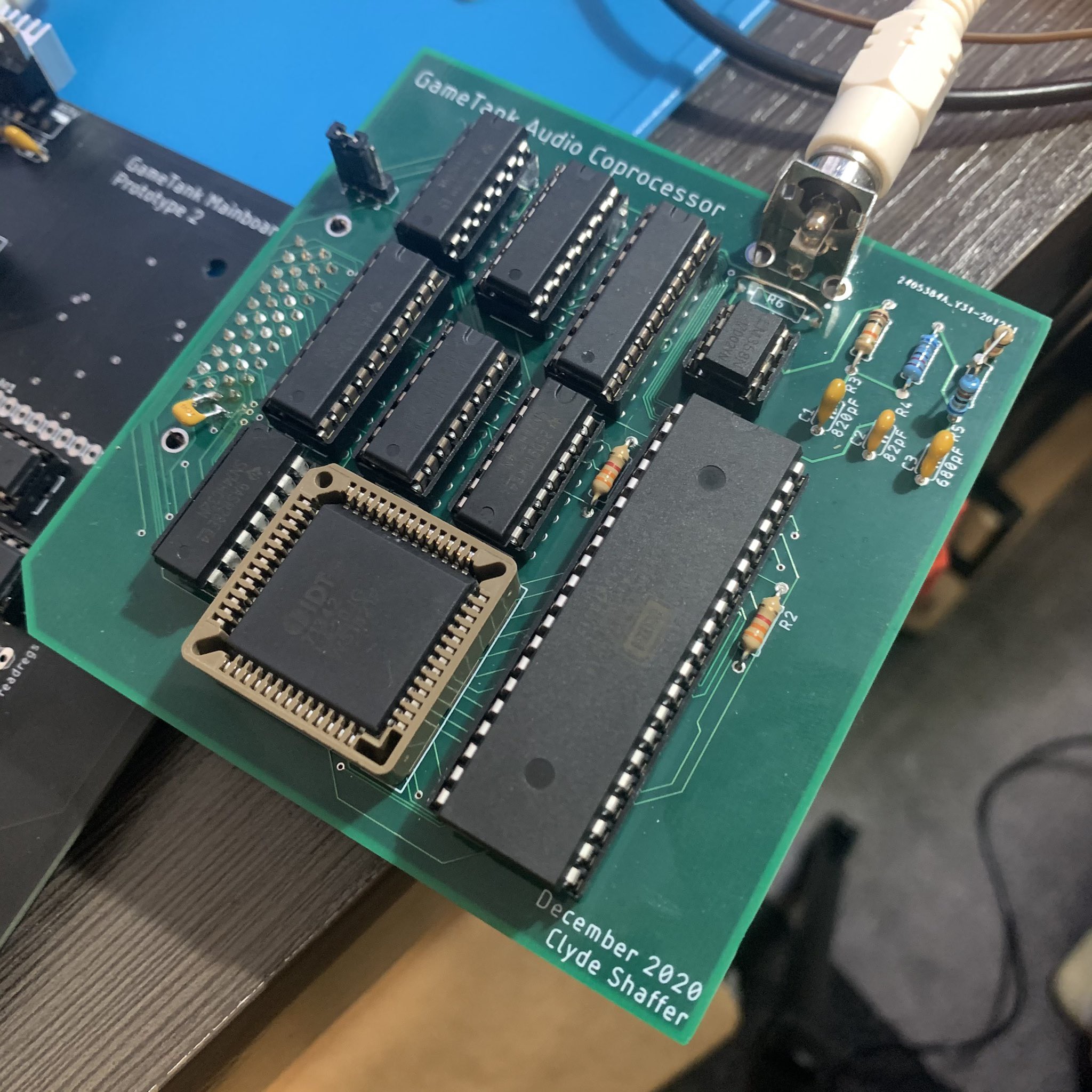
But what if the little computer-within-the-computer was equally as powerful? This seemed fine according to my completely arbitrary rubric, so I spun up a daughterboard design that simply used another 6502 to control a DAC.
![]()
The interface carried over from the old soundcard provides 7 memory-mapped selection signals, 4 kilobytes of memory access, and all four of the clock divisions used in the system. So it was relatively trivial to control the new Audio Coprocessor by loading programs into the dual-ported RAM and manipulating the RESET, READY, and NMI lines with the memory selection signals.
The design for this audio computer is actually pretty simple. The dual-ported RAM is wrapped around the whole 64k address space, while the DAC register is written on any write cycle while A15 is high. To prevent jitter on the audio sample rate, a 40103 8-bit down-counter is used to generate an interrupt that generates each audio sample. The samples sent to the DAC are double-buffered, meaning that every time the IRQ line strobes it copies the sample generated by the previous run of the interrupt handler. As long as the handler can complete in the time between samples, it doesn't matter precisely how long it takes to generate the final DAC value.
The jumper in the picture is for switching the coprocessor's clock between 3.5MHz and 7MHz. The system's main CPU runs at 3.5MHz due to the rather loose timing of the address decoding and the devices hanging off of the bus. I figured that the Audio Coprocessor could run a bit faster due to its simplicity, but I hadn't realized that it would even run fine at 14MHz. Not pictured is the bodge wire I added to let the audio system run at 14MHz, giving ample headroom for more complex audio synthesis routines.
Once I had determined that this new soundcard design was working, I wrote up a program for it that had similar capabilities to the original soundcard design. I'm not sure this technically qualifies as irony, but that code ended up being remarkably similar to what I had already written in C++ to generate audio in the GameTank Emulator. I'm not sure how many times in human history someone will replace a swath of C++ code with a call to a 6502 emulator performing the same computation.
To test out this device, I converted the music playing code from Cubicle Knight (the GameTank's flagship platforming game) to support the new interface as well as address four audio channels instead of two. Cubicle Knight only used two square wave channels for music, reserving the noise channel for sound effects and ignoring the PCM wavetable. The converted music player code uses the noise channel for percussion and utilizes the fourth channel for sine waves, in addition to the square wave instruments. For the song selection I went with the good ol' demoscene standby Bad Apple, itself a remix of a theme from the Touhou Project series of bullet hell games.
To encode the song I wrote a script in Node JS, which converts a MIDI file into a series of bytes that alternate between describing note length (in 60ths of a second) and note number. The script assumes that the MIDI file follows a certain rules and has a certain structure, so I had to painstakingly notate my own arrangement into a 4-track file. I also was forced to finally stop procrastinating on certain timing bugs in the conversion script, weren't noticeable in Cubicle Knight's soundtrack but became glaringly obvious after including a drummer in the ensemble.
The song runs at about three minutes, and uncompressed the song data weighs a "whopping" 8 kilobytes. Which is unfortunately the entirety of general-purpose RAM on the current motherboard design. To deal with this I borrowed some space on the video card, which has two 16k framebuffers and 32k of offscreen sprite memory. For the purpose of the video I chose to use the on-screen framebuffer to store the uncompressed song data on the top half of the screen, but it could just as easily be stored in sprite RAM.
Of course, my next goal will be to play not only the song data but also the animation that goes with it. The shadow art of the Bad Apple video reads well at low resolution, and compresses well being mostly monochrome. (Though the original does feature some grayscale). However, even when squeezed down to 128x96, converted into Run Length Encoding, and played at 15 frames/second, the frames of the video still add up to just under 2 megabytes. This dwarfs the size of the cartridges I currently use, which are essentially breakout boards for 8k EEPROM chips.
My next focus will be on prototyping cartridges that use parallel flash memory chips with a 2MB capacity. Since this is bigger than the 6502 can natively address, this will require a banking scheme. The prototype cartridge boards for which I am now awaiting delivery accomplish this by using a shift register to set the most significant address pin on the memory chip whenever A14 is low. The importance of that last qualification is that the CPU will always be able to access the interrupt vectors at 0xFFFA-FFFF and a program executing from the top 16k of memory will not be interrupted by a bank switch.
![]()
-
Gameplay footage
12/12/2020 at 18:57 • 0 commentsThis is a few months ago, running a game on the v1 prototype. Note the color artifacts on high-contrast edges, and how faint the player character's hair is against the black background. These have subsequently been fixed by redesigning the video signal combiner circuit.
The game runs at a consistent 60 frames per second thanks to the blitter, which is capable of writing every pixel on the screen over 800 times per second if needed. It also runs independently of the CPU, which is free to perform other tasks during a draw operation. Thus it is very cheap to clear the screen and redraw a tilemap every frame, as well as draw movable objects on top. The blitter has a transparency mode which can skip zero-valued pixels, making it simple to draw animated characters to the framebuffer.
-
Initial post to Hackaday.IO
12/12/2020 at 18:39 • 0 commentsI've already been working on this for about two years, but figured I might as well also give the project a profile on here.
The first physical prototype was assembled at the beginning of January 2020. It consisted of a backplane-style motherboard with cards for graphics, audio, and input. It used jumper wires to connect the selection outputs of the address decoder to each addon card, to maximize modularity. Overall the first prototype was good for proving initial design ideas and discovering the problems with my design. However, it was also quite fragile and unreliable.
Currently I am working with the second physical prototype, which trades much of the modularity for reliability and ease of inspection. The selection signals have been moved to PCB traces, while the graphics and audio board now use dedicated connectors. The boards are also arranged flat instead of at a right angle to the motherboard, for easier access with oscilloscope probes.
The primary remaining hardware issues are as folllows:
- The blitter has a glitch when the draw rectangle starts at an X coordinate ending in ****1111
- The digital potentiometers used for audio volume controls have been discontinued during the development of the project
GameTank 8-Bit Retroconsole
6502-powered game console with hardware-accelerated drawing

 The top board holds the composite video circuit on one side and the audio coprocessor on the other. So I call it the "Signals Board".