-
1Assemble the thing
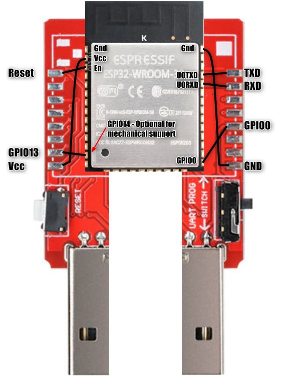
The wiring we'll aim at:
![]()
- Solder a cm or two of tinned copper wire to the TxD, RxD, GPIO0 and Reset (optionally GPIO13 for some added rigidity) pads of the DM-102
- Solder similar pieces of coated wrapping wire to Vcc and Gnd pads of the DM-102 (I used black for ground and red for Vcc)
- Place couple of layers of thick double sided adhesive tape on the DM-102, where the ESP32 is going to be placed at
- Place the ESP32 on the adhesive, pins aligned roughly as in the picture above
- Solder the wires to ESP32, peel the coated wires, cut all short after soldering
- Do continuity test between DM-102 pads and ESP32 pins, and between adjacent ESP32 pins to find unintended shortcuts
To test:
- Plug into a computer, keep finger on the ESP and power regulator on the other side to notice if they are heating abnormally (anything you'd feel in less than 30 secs or so)
- Turn Switch into "PROG", click the button, try flashing something from Arduino IDE or whatever, turn switch to "UART", click again, review results (serial console probably in this point)
If planning to use other GPIOs, it's easier to solder on the DM-102 before attaching the ESP module but can be done later. I strongly recommend soldering any required extra GPIOs also to the board as you won't get very robust connections directly to the ESP's crown "pins". A male / female header or DuPont connector can be hot glued to the other side for IO.
 Turo Heikkinen
Discussions
Become a Hackaday.io Member
Create an account to leave a comment. Already have an account? Log In.