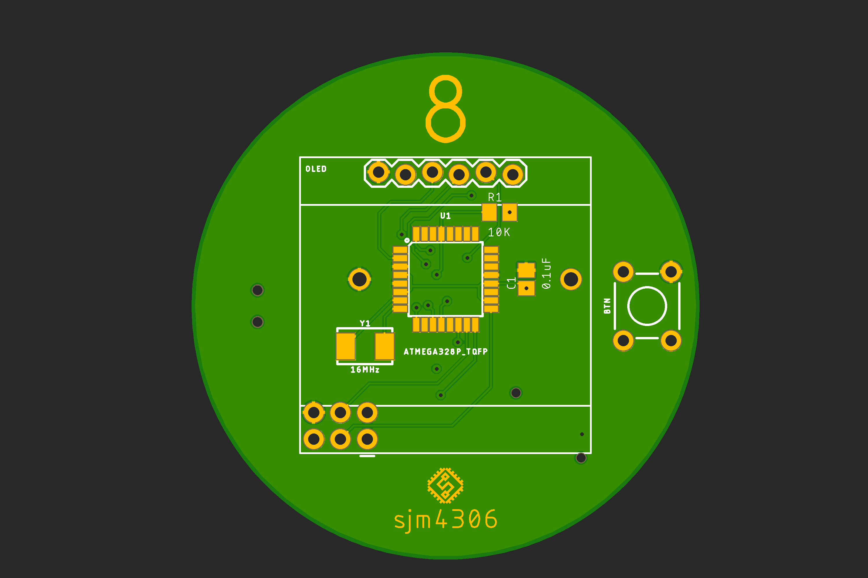
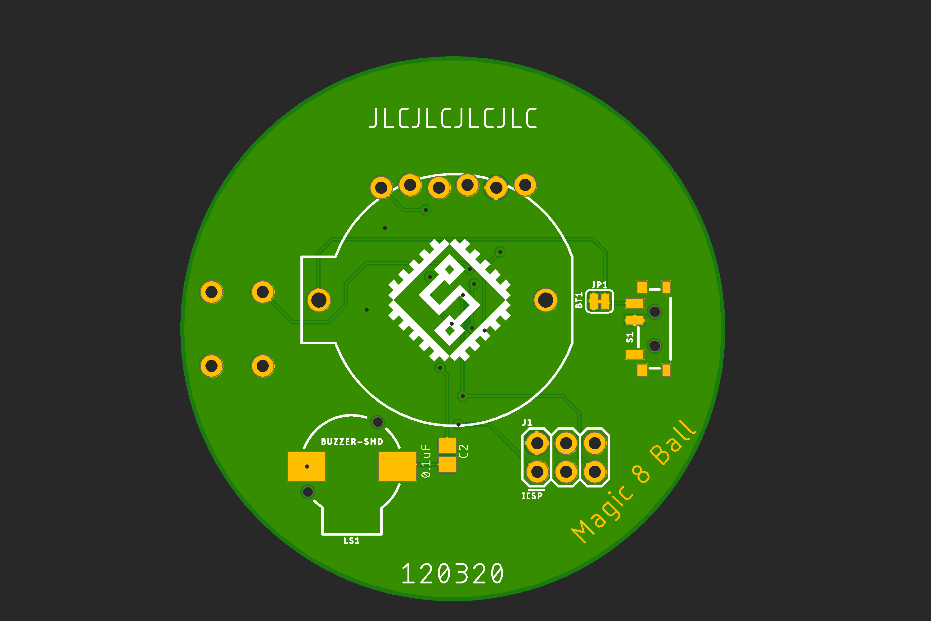
-
The 3D Printed Case
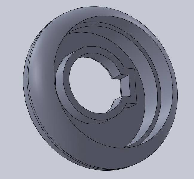
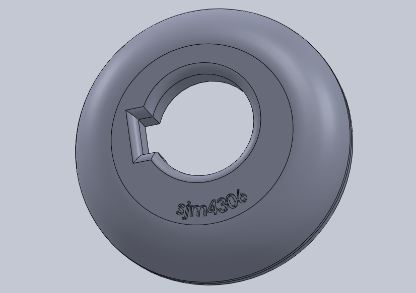
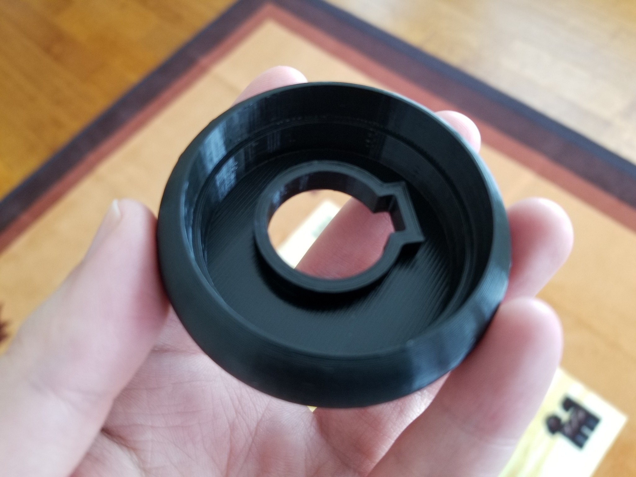
12/19/2020 at 18:53 • 0 commentsSo in a similar design vein to the programmer's converter dookickie I made a little while ago I decided to design a little bottom shell to house the bare pcb. For simplicity's sake I wanted to have a friction fit with no glue or fasteners required. To achieve a snug fit I referenced the pcb files to get accurate location dimensions and added about 0.5mm clearance between the pcb/components and the shell in areas where they would contact.
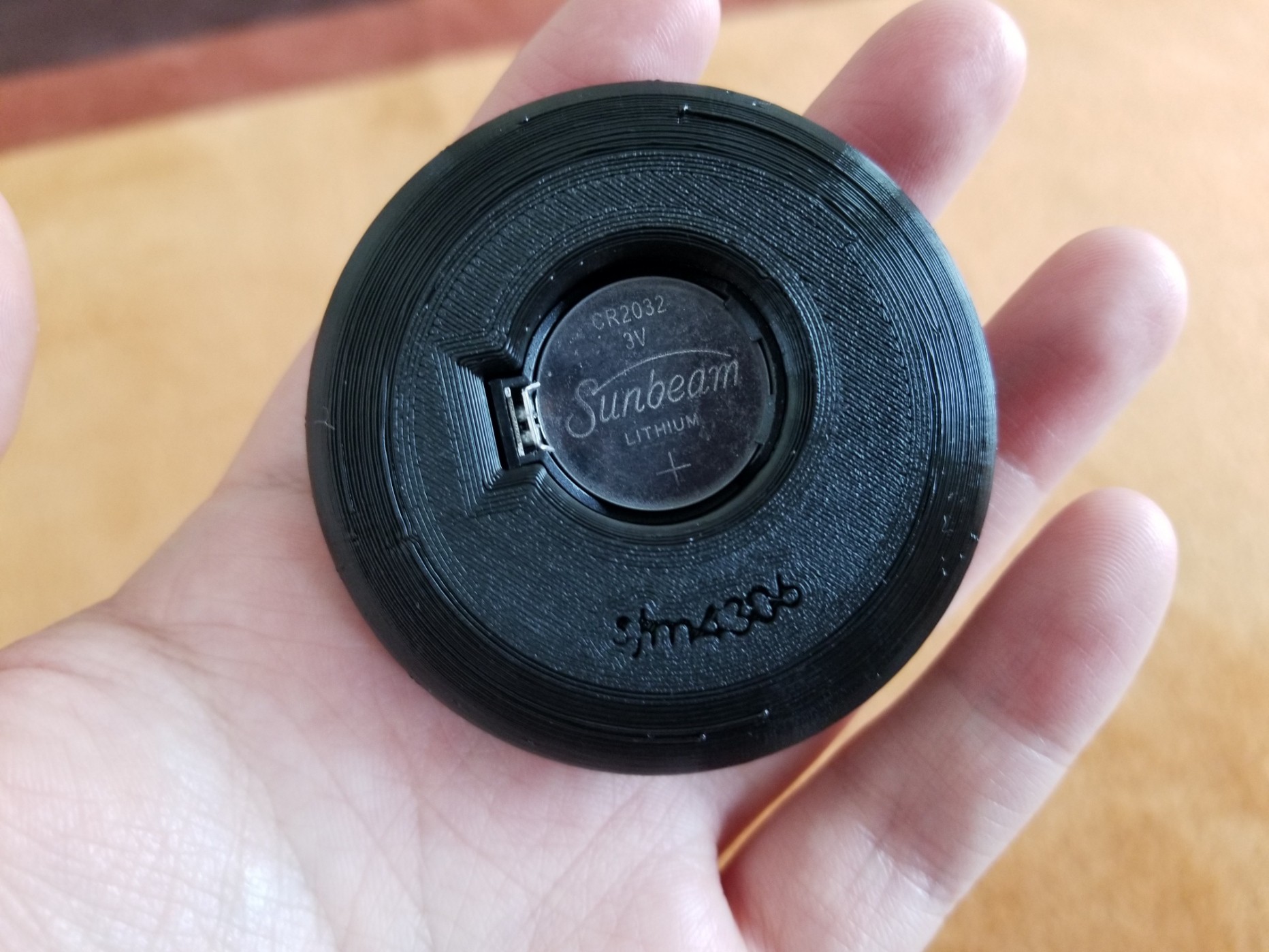
Additionally, in keeping with the 8 ball theme it'd have to be round but also have a flat bottom so it wont roll off the table (and be easily printable without supports). All these requirements led to a puck like shape with rounded corners and an inset void for the pcb to sit inside. I also borrowed the rear CR2032 battery hole from my converter design so it'd be easy to change the battery without removing the case.
These ideas condensed into this design.
Sort of looks more like a donut than an 8 ball but function over form I guess lol.
Printing took just under 2 hours on my Creality Ender 3 Pro and used 14g of black filament. The fillet on the bottom was 10mm but my printer was just barely able to print the overhang with a tiny bit of curling on the surface (in retrospect adding support or making the fillet less extreme would have solved this problem).
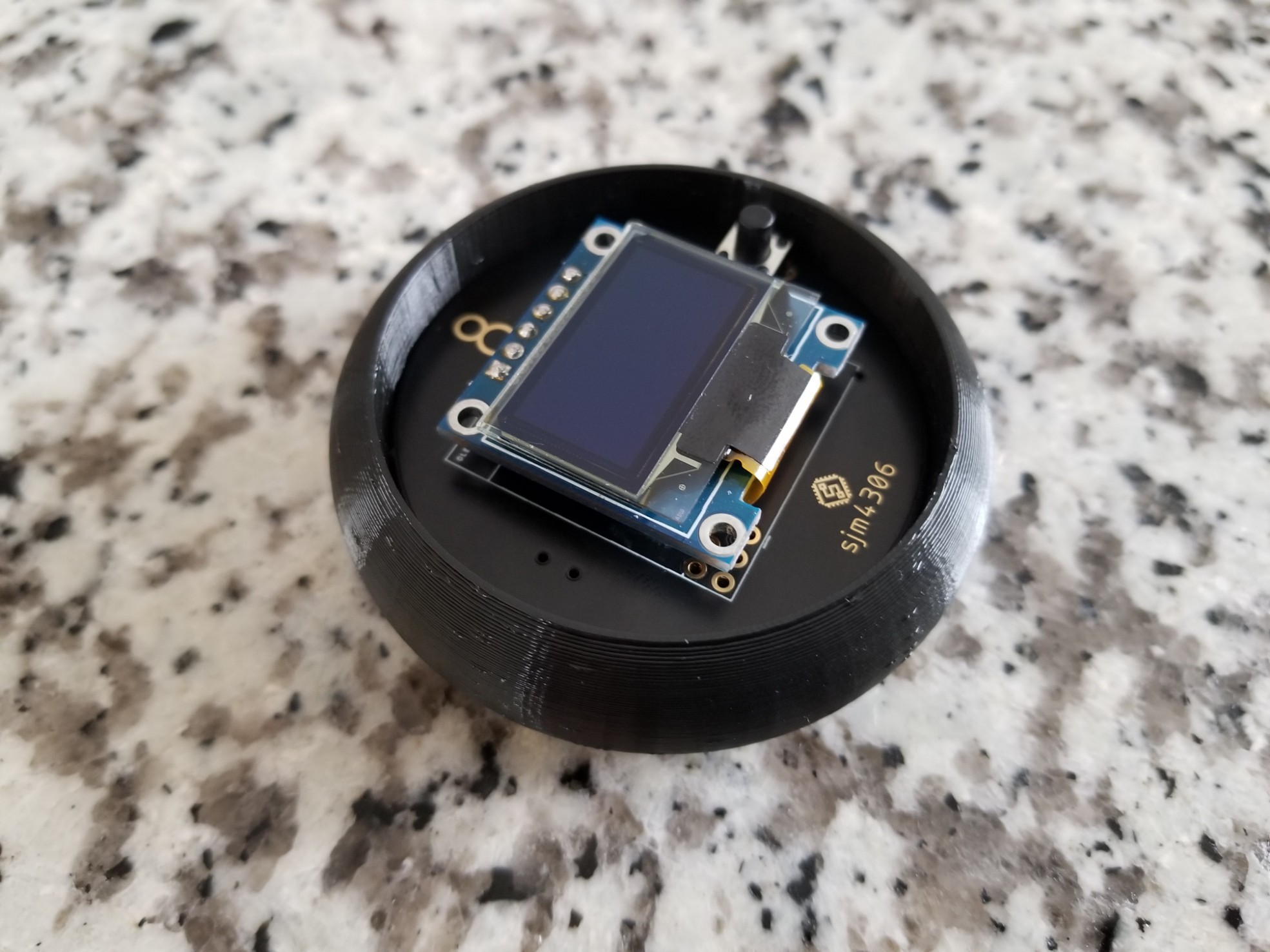
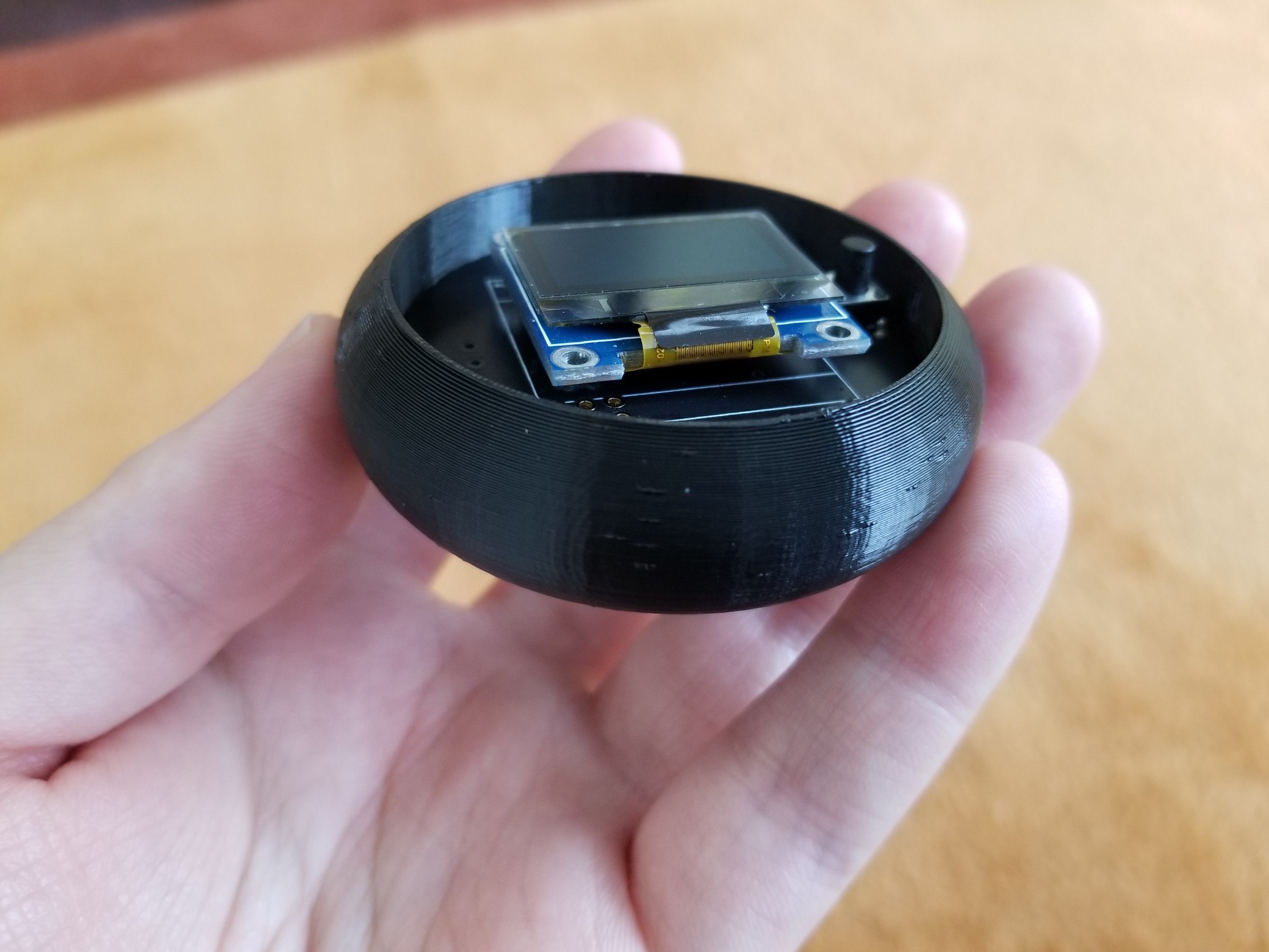
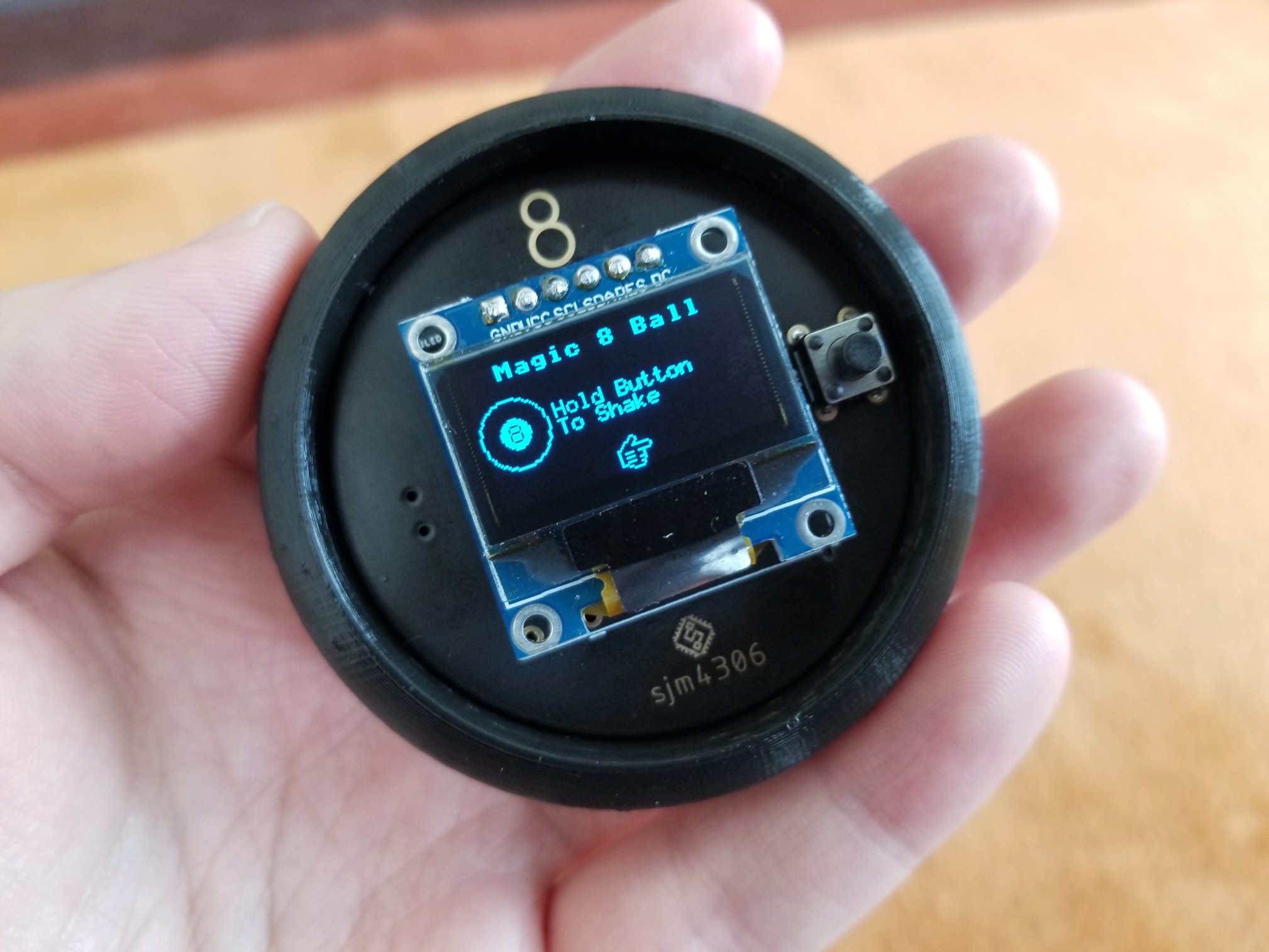
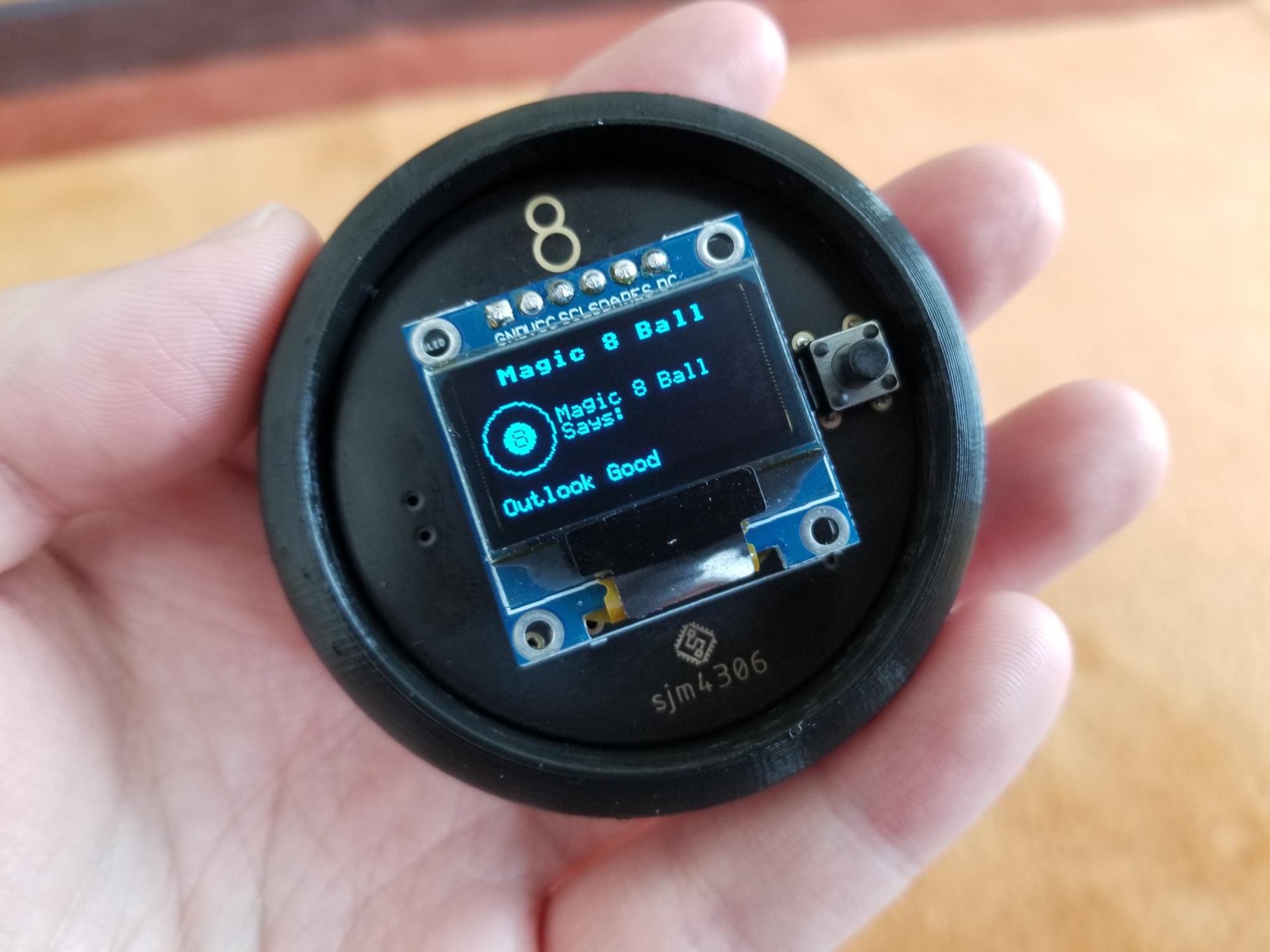
Pushing the pcb in was nothing short of satisfying. Everything fits as snug as a glove without being too tight. Here's how the end assembly looks with the pcb installed.
![]()
![]()
![]()
![]()
![]()
![]()
As a final note, I decided to leave the top uncovered. It'd be easy enough to design and print another piece that sits over the top with holes for the oled and button, but I kind of dig the look of the exposed black pcb with gold exposed metal pads and the screen and button are just about level with the top lip of the plastic. As for now I'll upload the solidworks and stl files for this print as I'm happy with the end result.
-
Assembling 1st Board, Software and Testing
12/17/2020 at 16:58 • 0 commentsSpecial Thanks to JLCPCB for sponsoring this project. JLCPCB Prototype for $2 (Any Color): https://jlcpcb.com
The board finally arrived so I rushed to assemble one to test. I filmed the process in usual fashion and to demonstrate the functionality.
![]()
![]()
![]()
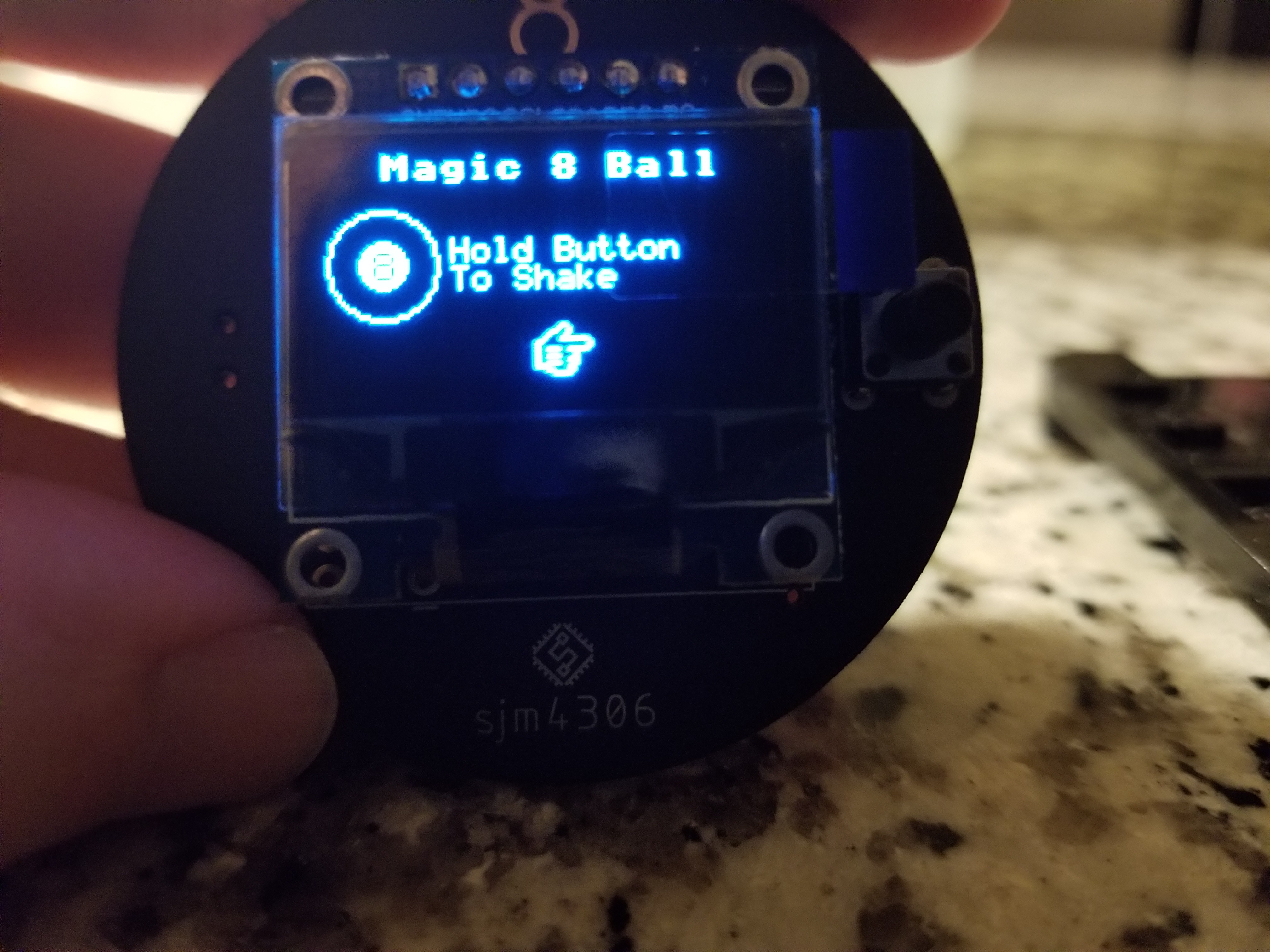
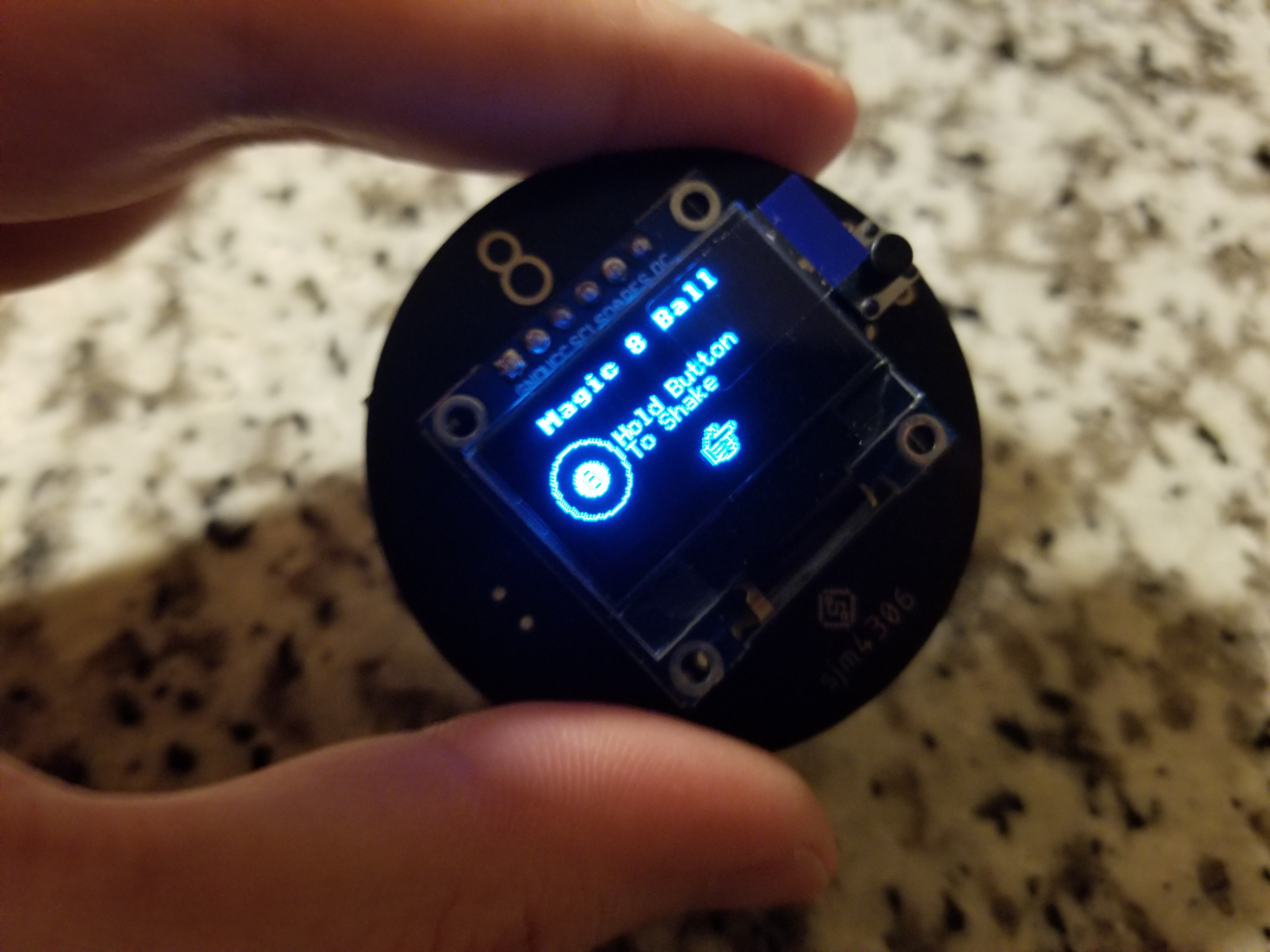
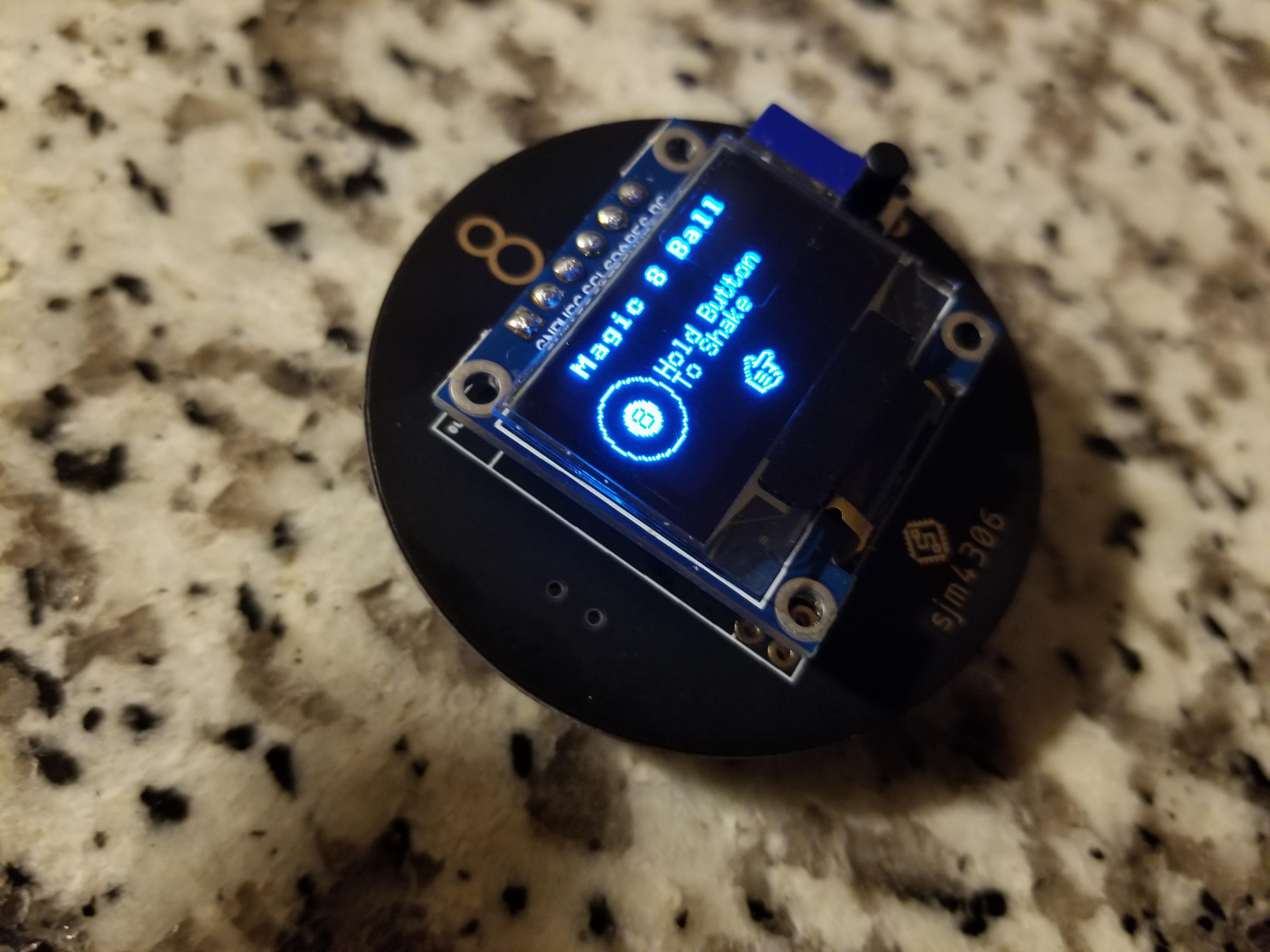
Here's a few glamor shots of the assembled pcb working.
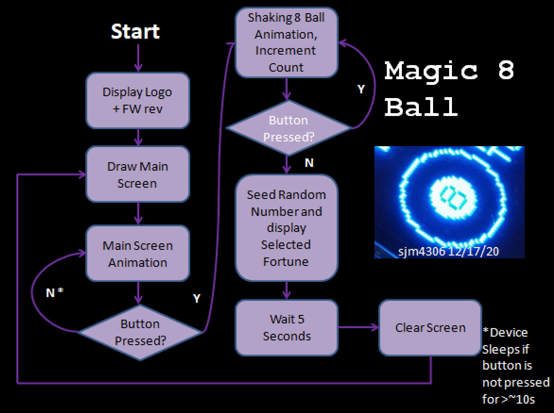
I didn't really go into detail how the software works in the video so we can explore that now. I drew a simplified flow chart to illustrate what the software generally does
The software is fairly simple with really only three main modes: the main screen, telling a fortune, and sleep. The transition between each mode is initiated as shown in the diagram above.
For selecting a random fortune to display, I opted for the age old psuedo-random function (basically a glorified linear feedback shift register). The main issue though is while seemingly random, without seeding a different value the sequence will always be the same. To get around this I count the length of time the user presses the button (and mask this by having them hold it to "shake" the 8 ball with accompanying animation) in order to seed the random function with a different value each time.
Now after assembling the first board I've found some things that could be further improved. For starters I didn't think about the battery holder placement and it currently blocks access to the OLED pin solder pads on the back so the screen must be soldered from the front. PCB rev 2 will have the battery holder moved down so that the pads are exposed and easily solderable from the back. Additionally I found that even in the deepest sleep state the atmega supports, the device draws somewhere near 30uA. While not horrible this means with a standard ~220mAh CR2032 battery, it will only last just short of a year on standby.
I have a feeling much of that is due to the OLED being permanently connected to the battery and relying on its own controller's sleep functionality. In the next revision I'll probably power the OLED supply pin directly from one of the atmega's outputs so it can be completely turned off during power down.
Now as for the final cherry on top before giving this to the recipient, I plan on 3d printing a little case to pressure fit the pcb into so it's better protected. The design for that will be covered in the next log. -
Background and Design
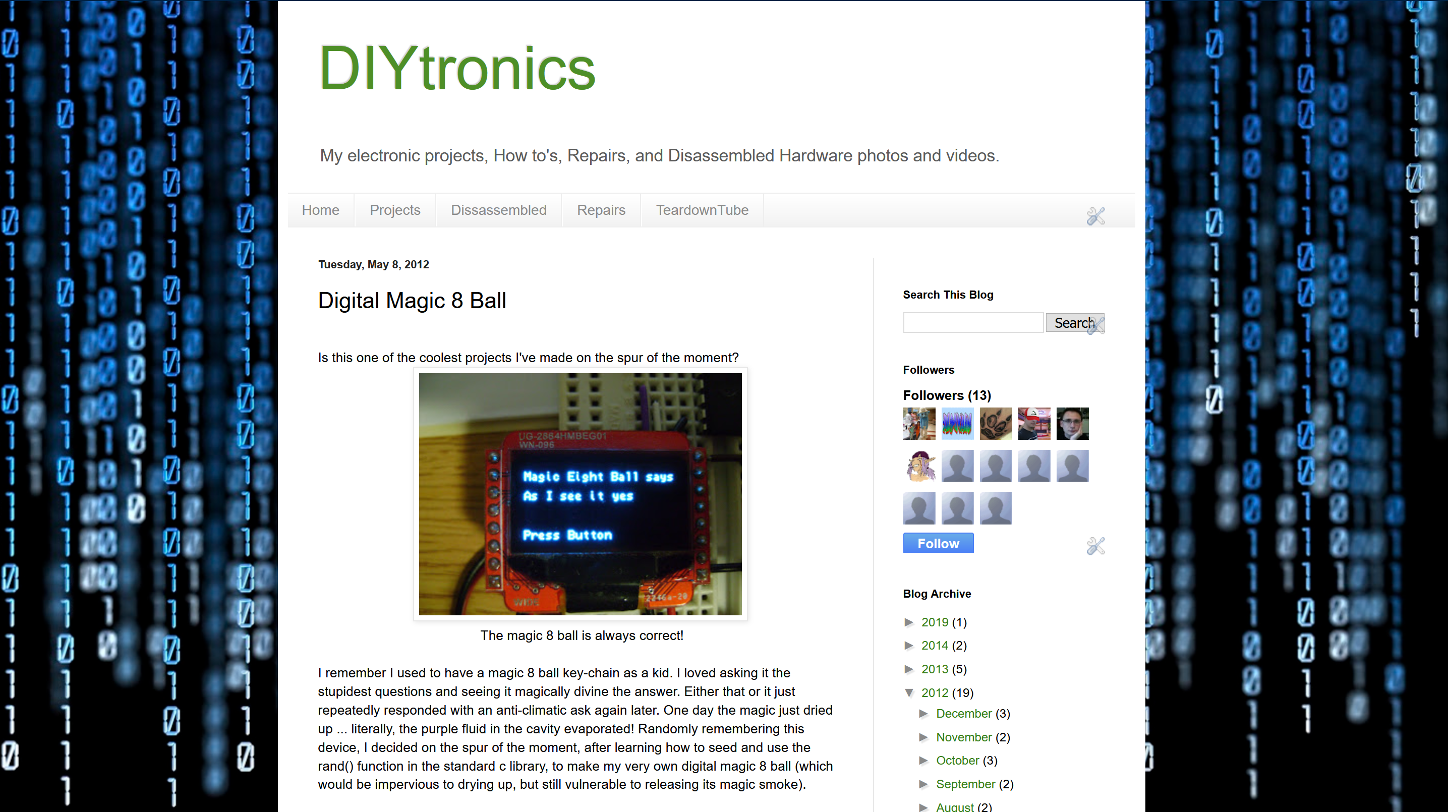
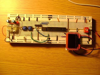
12/17/2020 at 16:24 • 0 commentsSo way back in 2012 I wrote up a crude article on my blogspot about a breadboarded digital magic 8 ball project I created (http://diytronics.blogspot.com/2012/05/digital-magic-8-ball.html).
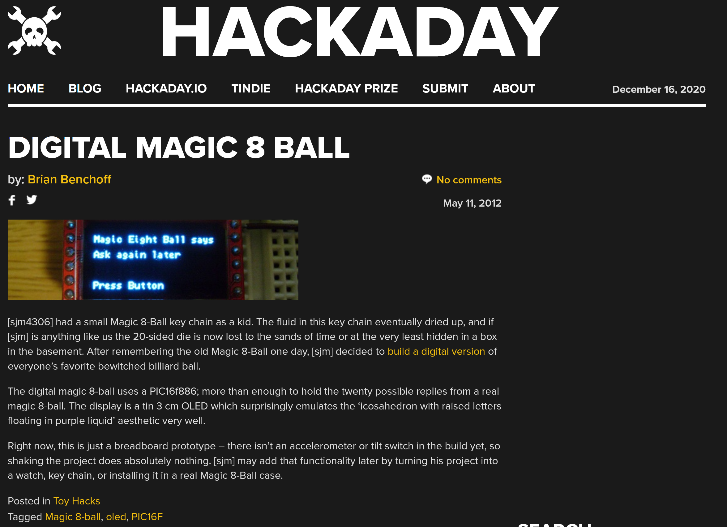
I just made the project on the spur of the moment while learning how to program for a new OLED screen I bought. To my surprise it was then picked up by HAD and became my first work that made it onto the site.
However, since then I was never satisfied with how I just left the idea unfinished and unpolished. So that brings us to now, I wanted to create a nice pcb for the project and add some niceties to the software/user interface. And given how much of a trainwrech 2020 has been I thought it'd be a nice way to send off the year and predict whether 2021 would be better!
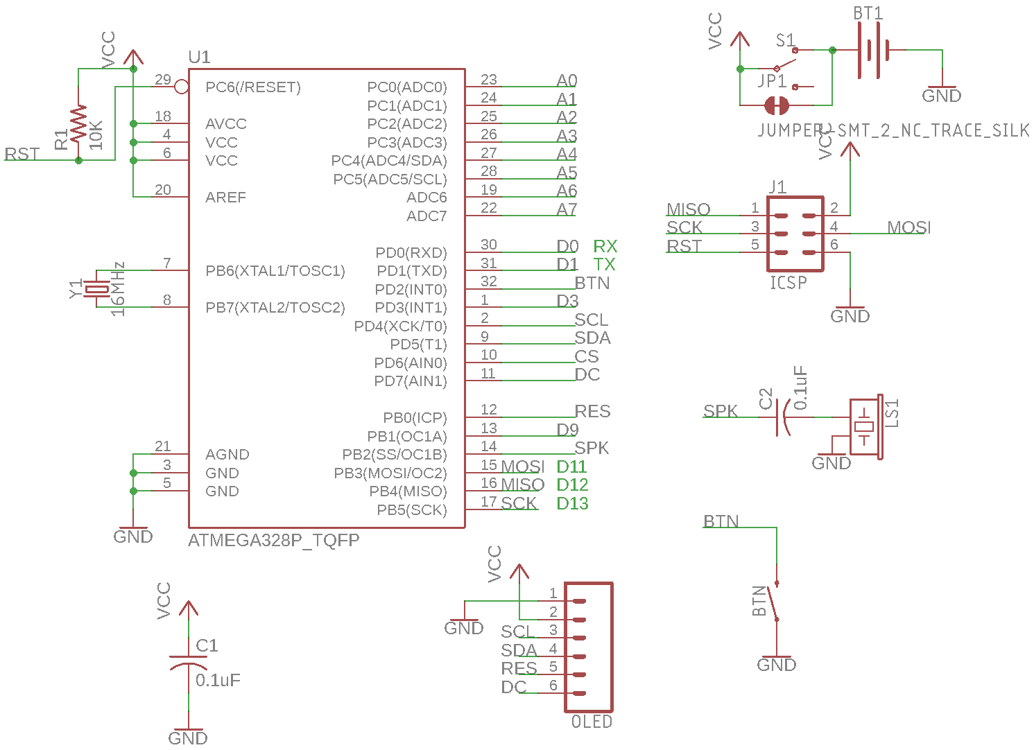
As with many small projects I just copied and pasted a minimum required part selection from a past project to get started.
![]()
I first decided on the shape of the board. Clearly since it was modeled after an 8 ball the pcb would have to be round. Additionally, taking some inspiration from tomagochis of the 90s/00s, I wanted to have it be keychain sized and the screen to be nicely centered. Back when I did the original prototype I dreamed of adding an accelerometer to detect a user shaking to initiate the fortune telling but I decided to scrap that idea in favor of a single button, both cheaper and simpler. Powering the device would be a single CR2032, cheap and widely available. Finally I wanted only the one button so I decided to use the microchip's lowest power sleep mode for soft power control that could be woken with a button press and would sleep after a short delay of no user input.
![]()
![]()
So with these general design choices in hand I threw together a board. Since the layout was pretty sparse and cost optimized I decided to throw in some optional extra features: a slide switch to manually disconnect the battery for longer storage and a small speaker to bleep/bloop when the button was pressed.
Luckily since the parts list is quite simple I pretty much already had most everything in my hoard (erm I mean collection). I intend to gift the finished device so I needed the board at least a week before the 25th so I rushed off to JLCPCB to place the order and have them rushed back to me. On the 15th of December they arrived and in the next log I'll document assembling, the software and testing the first revision.
Digital Magic 8 Ball (Mk.2)
One of my first projects ages ago was a Digital Magic 8 Ball on a breadboard ...
 sjm4306
 The software is fairly simple with really only three main modes: the main screen, telling a fortune, and sleep. The transition between each mode is initiated as shown in the diagram above.