doctek
-
Using the tArmDuino Serial Capability
09/20/2023 at 00:49 • 0 commentsTurns out that using the USART (serial) capability of the L071 is actually pretty easy. First, select "Enabled (no generic 'Serial')" from the Tools / U(S)ART support menu. Then, all that's required is to include HardwareSerial.h, instantiate a HardwareSerial object (call it mySerial, for example), and use it as you would use Serial in a Uno sketch. When you instantiate the HardwareSerial object, find the pin numbers to use in PeripheralPins.c and variant_SMALL_L071K.cpp. Specify the digital pin numbers, Rx first, then Tx. L071_serialLoopBack.ino is included as an example.
Using a serial to USB adapter (such as the ch340): connect the ch340 Rx pin to the tArmDuino Tx pin and you can transmit debug info. Obviously, connect ch340 Tx to tArmDuino Rx for serial input to tArmDuino.
-
Revising to Latest ST Software Design
09/03/2023 at 00:14 • 0 commentsStarting somewhere between release 2.0.0 (I think that's where it started) and the current 2.6.0 release of the STM32 MCU Based Boards, ST significantly revised the directory structure for variants and the contents of the variant files themselves.
The process documented in the Project Log "Adding tArmDuino to the Arduino IDE" is still correct in principle, but the details are incorrect. In this Project Log, I will basically follow the aforementioned, but I will provide correct details. Reading the old log will help anyone who wants to really understand this process.
For reference, I'm now running Ubuntu 18.04, but this should work with other recent versions and operating systems. My Arduino version is 1.8.15, but more recent versions should work also. However, I haven't tried Arduino 2.0 or later.
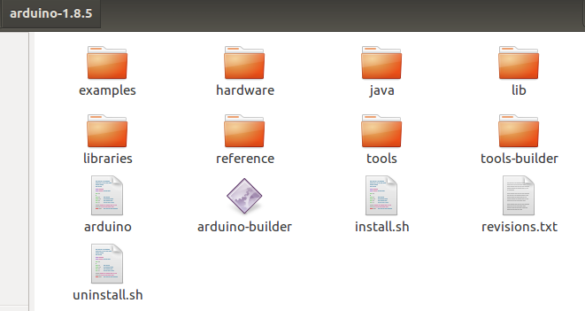
Let's get started. To begin, install the STM32 MCU Based Boards version 2.6.0. This isn't quite as clean as it might be and can't be done from the Arduino Boards manager as might be expected. Fortunately, ST provides simple instructions. Follow these, restart Arduino, and verify that the ST processors show up in the boards menu as shown in the instructions. (I'm not sure if you need to install STM32CubeProgrammer or not. If you try uploading to the tArm Duino from Arduino and it doesn't work, then install the STM32CubeProgrammer per the instructions.) I don't know exactly how to test this on my system, since I have all the tools in place.
There is still no entry in the STM32 Boards menu that is specific to the STM32L071, so I revised my previous board definition to meet ST's new requirements and added it to Arduino. This mainly required comparing my file and directory structures to versions in the ST directories. On my system, these are in ~/.arduino15/packages/STMicroelectronics/hardware/stm32/2.6.0. To guide these changes, the most useful references as of 2023 include these: Arduino documentation and Stm32duino documentation.These resources still point to three key details. First, I needed a board.txt file which defines the features of my board, and a platform.txt file which would define my programming method. All the software modifications are in the "variant" directory. I copied my old variant directory for the LO71K and began modifications. Comparing my files and directory structure to an ST32L072 gave me the information I needed to make things work again.. The modified files and directory structure are provided in the Files section as tDuino2.zip. Here are the modifications to the earlier versions:
platform.txt - I just added uploader tool and debugger configuration from ~/.arduino15/packages/STMicroelectronics/hardware/stm32/2.6.0/platform.txt. I'm not sure all these are needed, but things work. Currently, only the SWD uploader is used.
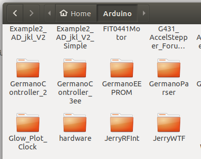
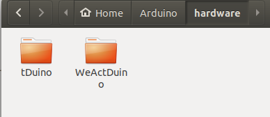
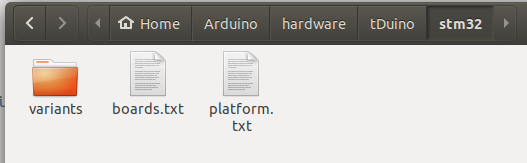
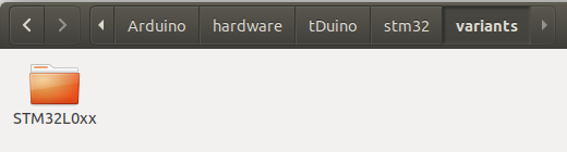
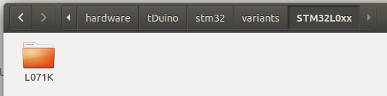
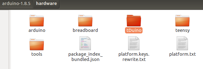
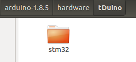
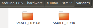
boards.txt - For this new version, I'm dropping the L031 variant and will only have the L071 variant. Several changes are needed in this file. Looking at ~/.arduino15/packages/STMicroelectronics/hardware/stm32/2.6.0/boards.txt showed me what to do. First, change the build.core definition from STM32:arduino to STMicroelectronics:arduino. Then add definitions for flash_offset and variant_h to the build section and change the value for variantThe second detail is to provide the directory structure required by ST for the variant. The following pictures show the structure from the Arduino Sketchbook leading to the L071K directory. (This structure is described further below.)
![]()
![]()
![]()
![]()
![]()
![]()
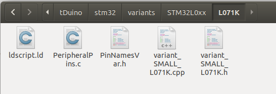
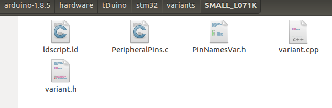
Seem a bit messy? All I can say is that ST is a European company, and the Europeans love structure. Perhaps the structure could be modified, but I don't see much point in trying to do that. Easier to just copy the structure. Anyway, inside the L071K directory, the files PeripheralPins.c, variant_SMALL_L071K.h and variant_SMALL_L071K.cpp define the pins on my board, the functions they support, and the mapping to Arduino digital and analog pin numbers (like D0 or A5). Note that pins PB_4, PA_13 and PA_14 are removed from PeripheralPins.c as these are unavailable on my boards. I also copied files ldscript.ld and PinNamesVar.h from the ~/.arduino15/packages/STMicroelectronics/hardware/stm32/2.6.0/variants/STM32L0xx/L072K(B-Z)U_L082K(B-Z)U directory. These latest versions are needed to work properly with the new ST structure.
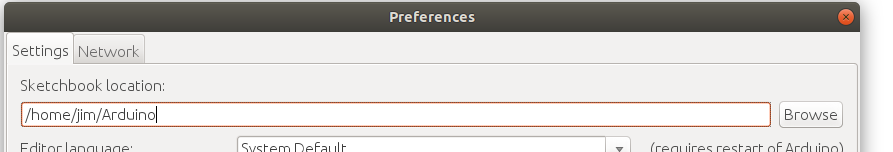
The third and final detail is exactly where to put the files so that my board will show up in the Arduino Tools/Board menu and my code will be compiled properly for it. The file map above starts with the location of the Arduino Sketchbook. The Arduino Sketchbook location is found from the Arduino IDE using File > Preferences. The Sketchbook location is the first entry in the window.![]()
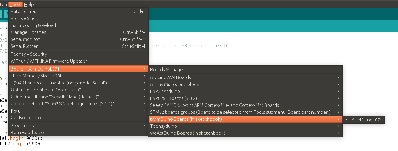
On my system, it is in ~/Arduino. In that location, I create a new directory named "hardware" (without the quotes). For anyone wanting to duplicate this, download the tDuino2.zip file and simply unzip it into the Arduino/hardware folder you created. Restart Arduino and you will find an entry for "tArmDuinoL071" under the title "tArmDuino Boards (in Sketchbook)"
![]()
Two minor notes if you try to duplicate my work: 1) Be sure you install the stm32duino files first! 2) The debug version and the tArmDuino version of the STM32L071 hardware are identical from the software side. One entry covers them both.
-
Uploading Clip for tArmDuino
01/13/2021 at 05:32 • 0 commentsThe uploading clip, mentioned in the Details section above, is slightly modified from the original. Following is a description of the version used for tArmDuino, how it's assembled, and how it's connected to the ST-Link.
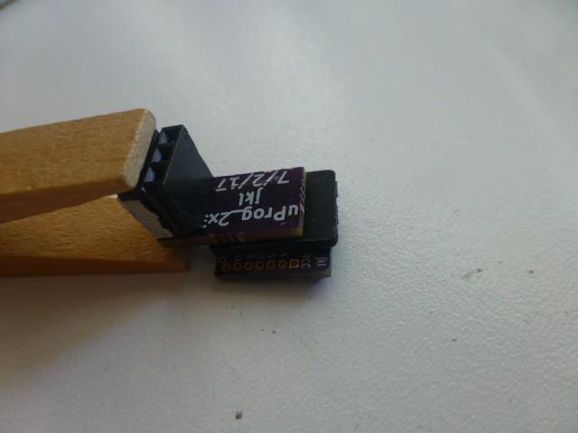
The circuit board and connector are unchanged. The KiCAD files have been placed in the Files section and include the gerbers and the solder paste stencil. Here is the board with the contactor in place.
![]()
The spacer or frame around the contactor is also modified compared to the original version. It now has locating tabs on two sides and is designed to fit tArmDuino. The stl version is in the Files section. After printing, it should be adjusted to 1.75 +/- 0.05mm thick. It's purpose is to keep the contactors from being crushed beyond their elastic limits, while still allowing them to make firm contact with the pads on the tArmDuino.
![]()
This shows the board with the contactor, and the tArmDuino in place on the frame.
![]()
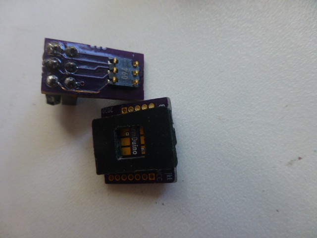
Here is the frame in place on the contactor. Note the orientation of the tARmDuino. Obviously, it gets flipped over to mate with the contactor, but note the alignment of the lettering.
![]()
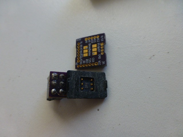
Shown here is the frame on the tArmDuino contact pads. Again, note the position of the lettering.
![]()
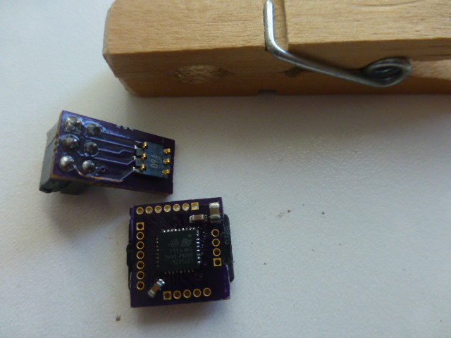
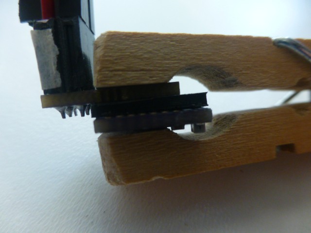
This is the stack up of the contactor, frame, and tArmDuino. The clothes pin is just used as a support here.
![]()
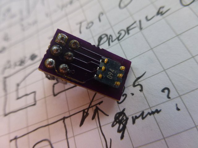
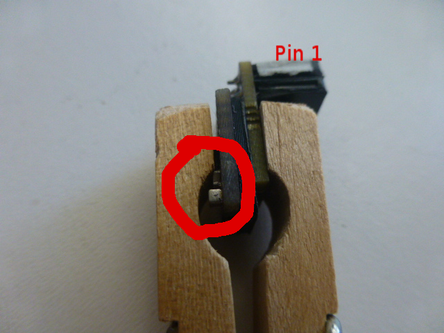
To hold the programming connector in place, an ordinary clothes pin is used. It is slightly modified using a file or rasp to make it fit securely and hold the connector squarely against the board. The pictures show the idea pretty clearly. Here it is shown in place. The white tape I placed on the wiring plug indicates pin 1, and the circle emphasizes the position of the two capacitors in the corner of tArmDuino (one larger than the other). These serve as a useful reference for correct orientation of the clip.
![]()
![]()
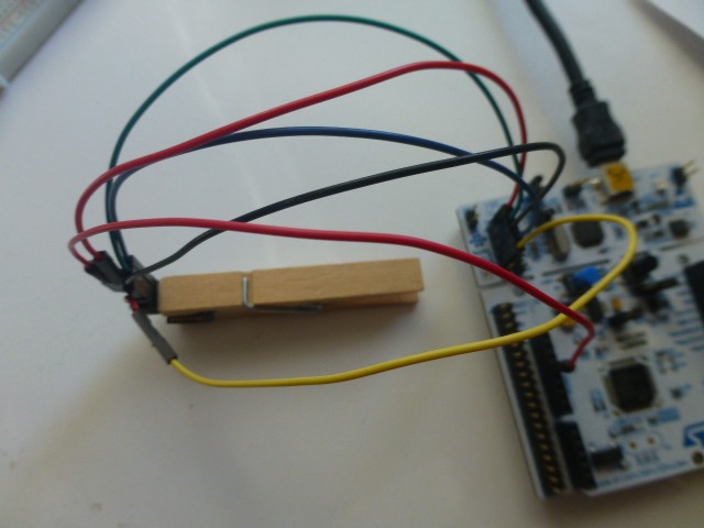
Here is the wiring to the ST-Link. Note that the pin names of the pins on the programming clip are changed for programming the tArmDuino. Pin 1 is nRst, 2 is Gnd, 3 is Vcc, 4 is SWC, 5 is Gnd, 6 is SWD. There is no need to connect both grounds, pick your favorite. Note that Vcc to the ST-Link must be connected as well to the 3.3V powering the tArmDuino (from the 3.3V power connector on the Nucleo, possibly).
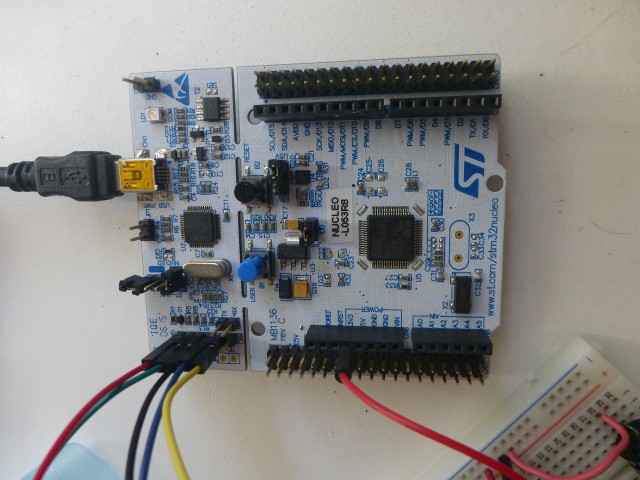
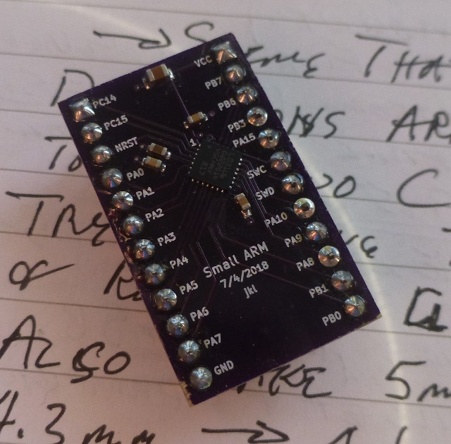
I used the Blink demo program (from Arduino/File/Examples/Basics) as discussed in the "tArmDuino Programming and Debug" build log above, changing led to 7 (PA8). The sketch was uploaded to the tArmDuino breadboard version, labeled "Small ARM 32", to make sure it worked. Not surprisingly, it worked! Then I wired up the debug clip as shown above and clipped it to the tArmDuino tiny version and uploaded to it. It works as expected. The tArmDuino is fully ready for whatever projects I can come up with!
![]()
![]()
These pictures show the tArmDuino hooked up to blink a led on a breadboard.Since the ST-Link is used to upload tArmDuino, it clearly could be used with gdb for debugging if needed. I personally prefer to debug using the Small ARM 32 (breadboard) version, then uploading to the tArmDuino, but there are times when it makes sense to debug directly on the tArmDuinon. This works fine, but sometimes any wires soldered to it can get in the way.
-
G-Debugger for tArmDuino
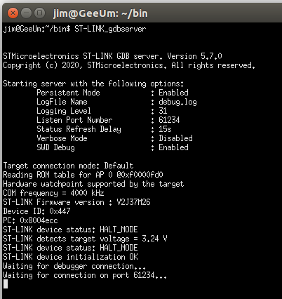
01/06/2021 at 04:32 • 0 commentsThe g-debugger (gdb) provides a very powerful debugging tool, but takes some extra effort to configure and use. It requires two parts that run in separate terminal windows. A gdb server must run in one terminal window and connects to the ST-Link. The gdb client runs in another terminal and communicates with the device being debugged via the server. The client is controlled by the person doing the debugging. The existence of this debugger is a strong argument for using an ARM processor! It provides much more robust and in depth debugging compared to the printf method, but requires more effort. I find it especially useful for hardware interaction problems. To use gdb, connect the ST-Link as described above, plug in the USB, start a new terminal window (I like UXTerm), and type ST-LINK_gdbserver. This will invoke the script in ~/bin and start the gdb server. It should now be waiting for the client to connect. I'll show this in action below.
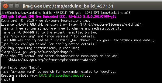
To make the most of gdb, I compile my sketch with Tools/Optimize set to Debug (-g). This causes symbols to be available for gdb to use. When I build my sketch, I just click Verify, not upload. Next I locate the elf file for my sketch. This will be found in /tmp/arduino_build_#####, where ##### is some random number that is created by Arduino. Arduino creates a new directory (and number) for each sketch that you compile, so, I make sure the correct sketch name appears in the directory, and that the creation time is correct. For example, if the sketch I'm working on is named My_Sketch, then I look for a file named My_Sketch.ino.elf. That's the one I will load with gdb. To do that, I will use the gdb supplied with the stm32duino package. On my system, I find arm-none-eabi-gdb in ~/.arduino15/packages/STM32/tools/xpack-arm-none-eabi-gcc/9.2.1-1.1/bin. Following Al Pacini's lead, I created another script to invoke gdb - named ARM_gdb - placed it in ~/bin, and made it executable. Here is the script:
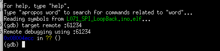
#!/bin/bash
~/.arduino15/packages/STM32/tools/xpack-arm-none-eabi-gcc/9.2.1-1.1/bin/*gdb "$@"
Here is what the server terminal looks like when the server is started:
![]()
Here is the client terminal window starting the gdb client
![]()
Now the client connects with "target remote :61234"
![]()
... and the server responds:
![]()
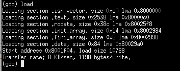
next the client causes programming of the flash with "load"
![]()
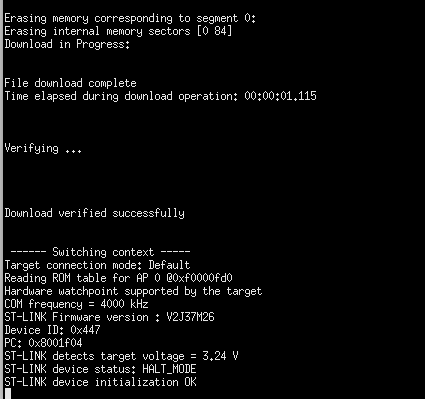
The server responds
![]()
![]()
and the debugging session can begin! The server responses are not used during debugging, but this is what you would expect to see if you use gdb. Enter "cont" in the client terminal to start the loaded program. Use "^C" to stop gdb when a sketch is running, then "quit" and "y" to leave gdb. Entering "^C" in the server window will stop the server. There is no need to stop the server if you plan to use gdb again. Be sure to stop it if you want to upload using Arduino IDE.
While those are the most basic gdb commands, that is a pretty boring example. Here is gdb being used for a typical, and more interesting, problem.
I intended to use nRF24L01 radio with the L071 tArmDuino as part of a control scheme. To control the nRF24L01, the SPI interface is used. The sketch compiled fine, but would not communicate using SPI. As a simple start to debugging, I created a sketch which just did a simple SPI loop back. (The sketch L071_SPI_LoopBack1.ino is in Files if you want to play.) Using the process just described, I loaded the sketch for gdb debugging.
Have a look at the sketch. It's very simple. The loop runs to simply transmit a byte and receive the same byte. Examining the three variables with gdb will verify that the SPI works in this simple way. If this doesn't work, then I have to fix it. If it works, then more debug is needed.
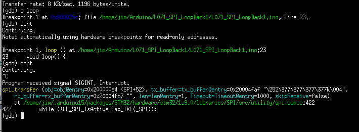
To start, I set a breakpoint with gdb at loop. Then I run the sketch with "cont". The sketch stops the first time loop is to be executed, as expected. Then I "cont" again expecting loop to execute once and stop just before executing again. At this point, I could examine the variables and see if the SPI is working. But, as you can see, there is never a second break at loop. I have to use "^C" to stop the sketch.
![]()
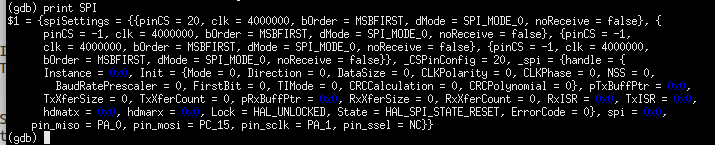
At this point, there are many gdb commands that can be used to explore the sketch. The source code for the SPI library can also be studied. Note that gdb even shows the path to the source code for the routine! But note that the routine where the forced break occurred is in the class named SPI (instantiated in SPI.h). To see the class data, I use "print SPI". Here's the result:
![]()
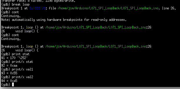
Look at the last line and note the pin names used for miso, mosi, etc. These are wrong! I went through the code and figured out why these pin names were used, but I won't bore you with the details, The observation that the pin names are wrong is the key point! The SPIClass has member functions that allow the SPI pins to be specified. These functions are used in L071_SPI_LoopBack.ino (also in Files). Using the same debug process, the SPI worked fine and I got the results I expected.
![]()
Inserting these defines into the nRF24L01 code made it work correctly! Rescued by gdb! This debug would have been very difficult with printf. Conclusion: Using gdb is a learning process in more ways than one. Not only do you learn about your program (sketch), but gdb itself has a rich command set. Learning and using gdb commands often provides additional insight into how sketches and libraries are constructed and how data structures are created by C/C++ in Arduino. It's a fascinating process that I always enjoy.
-
tArmDuino Programming and Debug
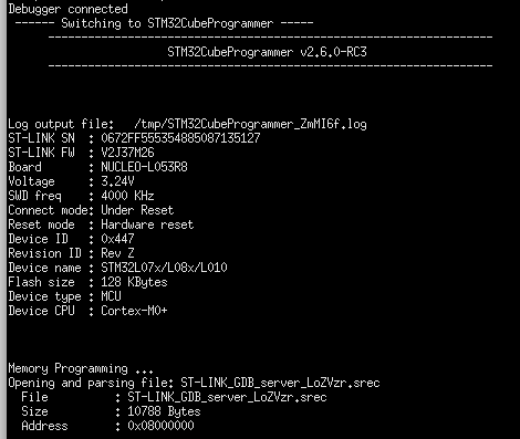
01/04/2021 at 01:08 • 0 commentsAfter adding the tArmDuino to the Arduino IDE, it is still not possible to program or debug it. The hardware and software tools to do that must be put in place. Programming and debugging tools for tArmDuino are all courtesy of ST. Although it's a large package, I recommend downloading and installing STM32CubeIDE. Since I use other STM devices, I find the Cube IDE useful, although the Arduino IDE is much easier to use for the tArmDuino. I will explain how to configure the programming and debug tools needed based on installing STM32CubeIDE. Although it may be simpler to install STM32CubeProgrammer instead, you still need STM32CubeIDE to get the gdb server. Al Pacini provided most of the hints and details that got my tools working.
The directory ~/STMicroelectronics/STM32Cube/STM32CubeProgrammer/ must be created if it does not exist. This directory was not created when I installed STM32CubeIDE, so I had to do it. If you install STM32CubeProgrammer (as Al Pacini suggests), it may be created for you. On my system (Ubuntu 16.04), the tools I needed were found in /opt/st/stm32cubeide_1.5.0/plugins/com.st.stm32cube.ide.mcu.externaltools.cubeprogrammer.linux64_1.5.0.202011040924/tools. Copy all the folders from that directory to ~/STMicroelectronics/STM32Cube/STM32CubeProgrammer/. When you are done, that directory should contain the folders bin, Data_Base, doc, and lib. Next, go to /opt/st/stm32cubeide_1.5.0/plugins/com.st.stm32cube.ide.mcu.externaltools.stlink-gdb-server.linux64_1.5.0.202011040924/tools/bin and copy all the files in that directory to ~/STMicroelectronics/STM32Cube/STM32CubeProgrammer/bin. From the software tools side, tArmDuino can now be programmed from the Arduino IDE. If you try this yourself, note that the numbers in the file names given may vary, but should be close enough to guide you. I went the step farther and followed Al Pacini's suggestion to create a ~/bin directory and put a couple of scripts in it to make the programming tools easily available from the command line. The udev rules should be in the right place following installation of STM32CubeIDE, so those files are not needed.
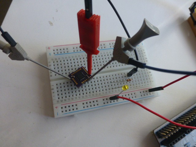
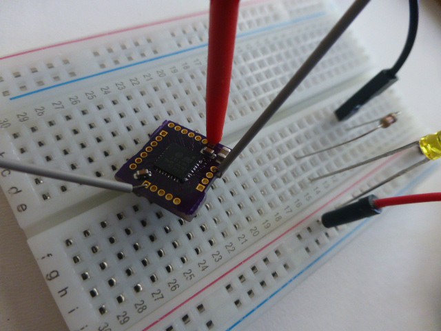
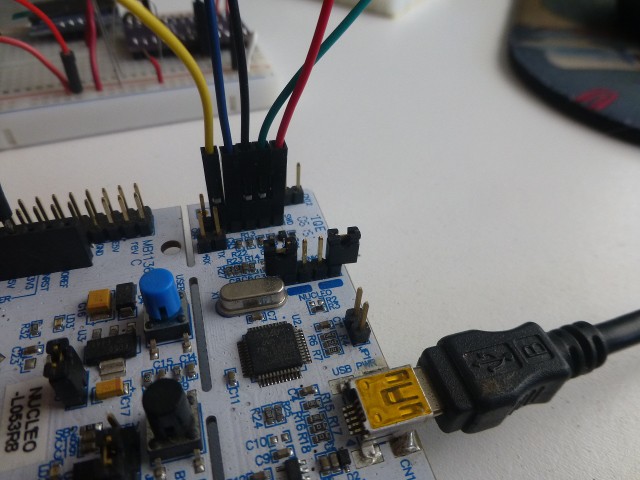
To program tArmDuino from Arduino IDE, an ST-Link programmer is needed. The cheapest and easiest way to get one of these that I have found is to buy a suitable Nucleo-64 board. I like the NUCLEO-L053R8 board. Following the manual for it, I remove the jumpers on CN2 (marked ST-LINK) and connect the CN4 (SWD) header to the breadboard version of tArmDuino. Plug the pcb into a breadboard for experimenting. Connect CN4-Pin 1 to the positive rail of the breadboard. This does not power the L071 during programming! 3.3V must be supplied; I use the 3.3V from the Arduiono header on the Nucleo. CN4-Pin 2 goes to SWC, CN4-Pin 3 goes to ground, CN4-Pin 4 goes to SWD, and CN4-Pin 5 goes to NRST. Here's how it looks in a typical setup.
![]()
Note 3.3V from Nucleo board to breadboard.
![]()
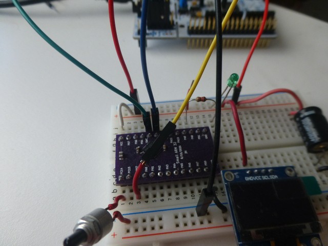
Note colors of wires. The picture below shows them connected to the STM32L071 tArmDuino.![]()
Once the ST-Link is connected, programming is easy. I select Board: tArmDuinoL071, Flash size: 128k, Optimize: smallest, Library: Nano (default), U(S)ART: disabled, and Upload method: Cube Programmer (SWD). I plug in a USB cable to the Nucleo/ST-Link. Then I load the Blink sketch from the Arduino Examples/Basics menu, change the led number to 7, and click verify to be sure it all builds cleanly. Then I click upload to burn it to flash on the tArmDuino. An led must be hooked to Pin PA8 via a resistor to ground or Vcc. Once the sketch is uploaded, the led should be blinking. The variant.h file in SMALL_LO71K has the mapping of Arduino pin numbers to tArmDuino pins named on the pcbs.
While the method just described works great, there are two shortcomings. First, there is no serial port available so the usual printf debugging is out. (The L071K has a UART, but I haven't implemented it.) Second, the powerful gdb (g-debugger) is not supported by the Arduino IDE. The use of gdb will be the subject of another project log.
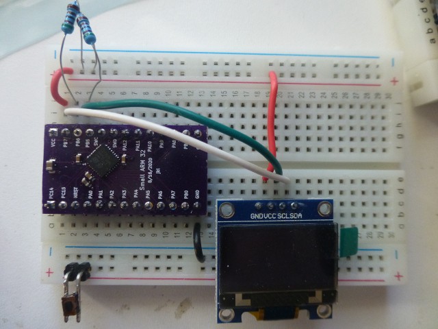
Let's look at the first shortcoming of the simple method of uploading from Arduino: no serial port is available for printf debugging. I have found a very satisfactory solution to this problem. The tiny SSD1306 OLED display (available from many vendors) uses the I2C bus and can display 8 lines of 21 characters. That's a lot of debug info! Using it is easy. Connect 3.3V to Vcc, gnd to gnd, SCL to PB7 on the tArmDuino breadboard version, and SDA to PB6. (I should mention that the demo sketch from Adafruit for the SSD1306 was my first serious test of using the STM32L071. Since the demo compiled and ran easily, I felt a surge of confidence that using the STM32L071 was a viable idea!) For anyone interested, the sketch L071_ssd1306_MenuDemo.ino is provided. First, get the SDD1306 library (AdaFruit version) using the Arduino Library Manager, load the sketch, verify, then upload. The sketch also assumes a pushbutton to ground on pin PC14. Press the button to start the menu system. Push/release the button to cycle the menu; push/hold for 3 seconds to select. Following this demo, you should find it easy to use the SSD1306 for debugging and display.
-
Adding tArmDuino to the Arduino IDE
12/29/2020 at 21:04 • 0 commentsThe stm32duino project supports a large number of ST microprocessors and boards. One of the processors it supports is the STM32L071! So the first step in developing software for the tArmDuino is to add these files to Arduino. I followed the Getting Started section at the stm32duino github page. After following the directions, I restarted Arduino, and verified that I now had a heading in the Tools/Board menu that said "STM32 Boards (selected from sub-menu)" with a number of selections below it. I don't really use any of this, but the libraries that accompany the package are just what I need.
There is no entry in the STM32 Boards menu that is specific to the STM32L071, so I had to create a board definition and add it to Arduino. While there is a lot of documentation available, most of it seems to be for the commercial developer and contains way more information than the individual needs to just add a single board. At the same time, key details seem to be glossed over. So some detective work and a lot of experimentation was necessary to add the tArmDuino! These references were particularly helpful: Arduino documentation, Stm32duino documentation, Rick Kimball's excellent example.
Mining these resources, I discovered three key details. First, I needed a board.txt file which defines the features of my board, and a platform.txt file which would define my progamming method. Mostly, this means definitions that will be pulled into the recipes for compiling, linking, and uploading the code for the board. Modifications started by copying the boards.txt and platform.txt from the stm32duino download. (These were in ~/.arduino/packages/STM32/hardware/stm32/1.9.0 on my system). Making an educated guess, I modified the boards.txt file to only include the Nucleo_L031 board and changed the occurrences of "31" to "71". Another change was to put the definition "[name].core=STM32:arduino" in which caused Arduino to use the tools in the STM32 Boards area that I previously installed. Finally, I caused a menu to appear in the Arduino Tools drop-down so that the memory size could be specified. Another menu allows choosing the upload method, although the only choice is to use SWD. There were already menus for optimization, C runtime library, and U(S)ART selection (not implemented yet). The platform.txt file was edited to only include the SWD upload method. Have a look at the versions I provide in the tDuino.zip archive.
The second detail is to provide a variant directory with the same name as is in the boards.txt file. In this case, that is SMALL_L071K (name is arbitrary). Inside that directory, the files PeripheralPins.c, variant.h and variant.cpp define the pins on my board, the functions they support, and the mapping to Arduino digital and analog pin numbers (like D0 or A5). I started by copying from the Nucleo_L031 board and carefully modified the files for the tArmDuino. While I'm still experimenting in this area, it all seems to work!
The third and final detail is exactly where to put the files so that my boards will show up in the Arduino Tools/Board menu and my code will be compiled properly for them. I'll skip the details of the many experiments I tried before I figured this out. The trick is to build a suitable directory structure and put that in the correct location. Cut to the chase: Build the structure shown and put it in the Arduino home directory in the hardware folder. The following pictures show how it fits together.
![]()
![]()
![]()
![]()
![]()
![]()
For anyone wanting to duplicate this, download the tDuino.zip file and unzip it into the Arduino hardware folder. Restart Arduino and you will find entries for "tArmDuinoL031" amd "tArmDuinoL071" under the title "tArmDuino Boards", right after the many entries defined for official Arduino boards. The L031 version only works with the 28 pin first version. I include it as a useful example and because I still use it sometimes. This method of adding a new board to the Arduino environment is not the official one! But the official one involves distributing from a web site and other overhead that an individual (at least this individual) may not be inclined to do. The method I describe works and gives the desired result. The downside is that this will need to be repeated whenever a new Arduino version is loaded.
Two minor notes if you try to duplicate my work: 1) Be sure you install the stm32duino files first! 2) The debug version and the tArmDuino version of the STM32L071 are identical from the software side. One entry covers them both.
-
Second Version - STM32L071KBU
12/28/2020 at 23:09 • 0 commentsUsing all that I had learned from my initial design, I bravely launched into a revision. It is called "tArmDuino". The STM32L071 seemed like the right family and I expected to use a 28 pin version again. But the 28 pin version only supported 32K of memory! To gain access to the larger flash memories, I would have to use a 32 pin package. Fortunately, the re-design was not difficult and the resulting board is only 1mm longer, and the same width, so no changes to the frame for the programmer were needed. The breadboard version is 26 pins vice 24 pins. Note that pin PB4 is a no-connect, according to the errata sheet. Actually, it's not totally clear to me what versions this applies to, so I'm just not using PB4. The complete part number is STM32L071KBU6 for the 128K part. Change the B to a Z for the 192K part. It's worth noting that there is an STM32L072KBU that has the same footprint and pin-out, and adds two DACs and crystalless USB. I haven't tried this chip yet.
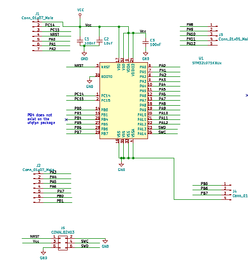
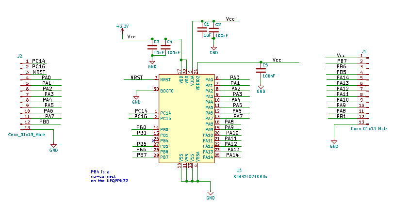
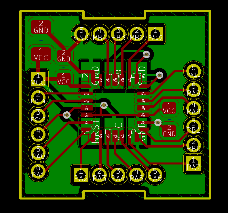
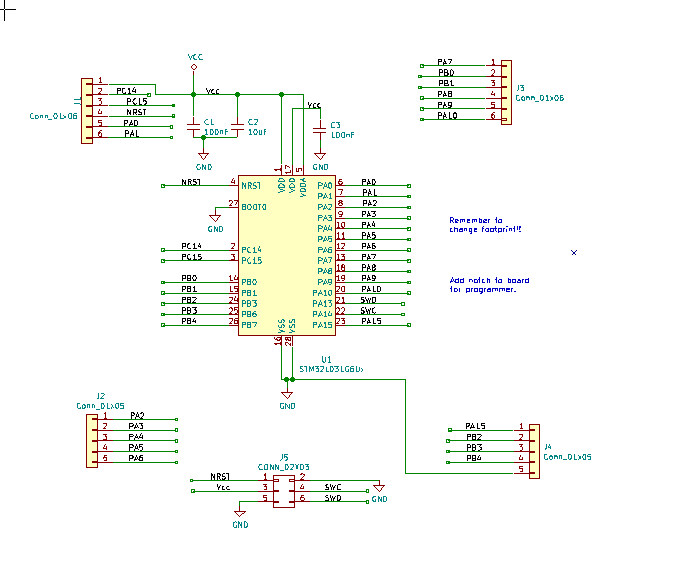
Here are the schematics for the tiny version of the tArmDuino and the small (breadboard) version.
![]()
![]()
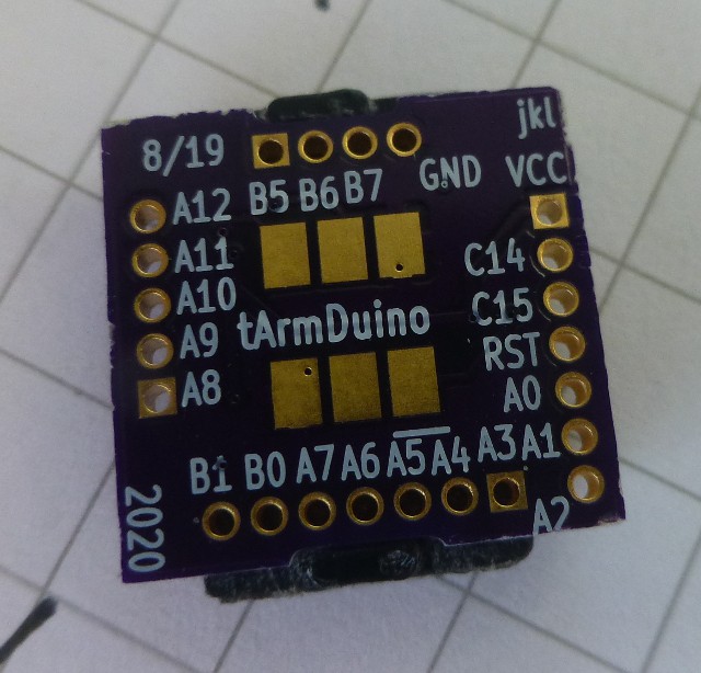
Besides dividing the pin connections into 4 connectors instead of two, the main difference is that the SWD and SWC lines (used for programming and debug) are brought out to the connectors on the debug version, while they are routed to the debug footprint on the tiny version. The pictures of the two boards follow.
![]()
![]()
The tArmDuino is shown sitting on the debug alignment frame. The breadboard version is shown in use. Details on connecting the STLink programmer will be given in another project log.
Building both boards uses standard process. The boards were produced by OSHPark. The solder paste stencils were cut on my Silhouette Portrait in 2 mil mylar. I stenciled on the paste, placed the parts, and reflowed using my modified toaster oven. Any required touch-up is done by hand.
The KiCAD files are in the Files section for both boards. Also included are the gerbers and the gerber for the solder paste stencil. Note that the stencil has rectangle vice rounded rectangle shapes for all pads. If I use rounded rectangles, then cutting the stencils with the Portrait takes a painfully long time! Since all the KiCAD files are available, a different stencil could be created if desired.
-
First Version - STM32L031G6
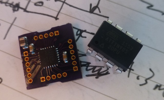
12/22/2020 at 02:04 • 0 commentsFor the initial design of a tiny Arduino, I chose the STM32L031G6 microprocessor. I had already determined that the SWD programming and debug port would work with the footprint I had developed for the ATTINY84 (link above in the Description). The 28 pin version seemed to cover all Uno functionality, plus. And I naively thought that 32K of flash (same as an Uno and Teensy2) would be plenty. There was a Nucleo 32 board with a 32 pin version of the L031 which I bought for testing. The first two boards (the tiny version and a breadboard version) were designed and are pictured below.
![]()
![]()
The resulting tiny version was not quite as small as an ATTINY85, but it's still pretty small! There are only three decoupling caps on the tiny version due to it's small size. Some might quibble with that decision, but it works so far. The BOOT0 pin is tied low since the SWD port is used to load code and debug. Everything else found on an Uno is omitted. I add circuitry if it is needed for a particular application. So far, I have had to add the I2C pull-up resistors. A voltage source must be provided in the 1.8V to 3.6V range - I use 3 to 3.3V typically. Note the notches on the sides of the board. These are to position the programmer. (Described later.) The breadboard version is also useful as just a low-cost Arduino to use with projects. Here is the schematic and a view of the board design for the tiny version.
![]()
![]()
Since this version has been deprecated, the KiCAD files are not included.
While I thought the hard part of the design would be the hardware, I expected the software to be easy. I knew that there was a version of the ST software for Arduino (via the usual Library Manager) and I expected to just use that. However, when I tried a simple I2C program, I was shocked and saddened to see that it took 22K of flash (70%)! Since a similar program on a Teensy2 takes only 5K (15%), this was a show stopper! There followed many months of learning much more about the Arduino environment and the internals of the ST32L031 than I ever intended. I won't bore you with details of the forum posts and how to use the LL version of the ST library vice the HAL version, but the result was that the I2C program now ran in only 3.7K (12%) of memory. More work was required to make analog pins (ADC and PWM) work properly, implement a timer, and have GPIO working. I still needed to implement SPI and the UART. To get things this far, I had modified the STM Arduino Library to use my code and to recognize my unique board. (I'll discuss necessary modifications in the next Build Log.) But I realized there is no future in this path! I don't plan to support custom software which might have to track new versions. And much better integration with the Arduino environment is needed.
Getting to this stage took over a year. I spent another 6 months or so mulling over how to proceed with this project. I really liked the concept, but the software details were killing me. Fortunately, by this time ST had introduced the STML071 series. This series had much more flash: 64K, 128K and even 192K. There was also a new rev of the Arduino Library. A few experiments convinced me that I could use unmodified code and fit it easily into these larger memories. The ST code is still bloated for these small processors, but the additional memory makes them usable. On to the next version!
Tiny Arduino for Hackers
A dime-sized, ARM-based Arduino complete with a programming/development system.