Keenan Rebera
-
Bluetooth App Demonstration
12/21/2020 at 20:45 • 0 commentsJust a quick demo of the app in realtime and my submissions to the "Goodbye, 2020!" Hackaday contest. I think the display / countdown fit the bill nicely, and since this project took all year, I'm pretty excited to celebrate where it's at!
Here I have in set as a big countdown timer until Jan 1, 2021 at midnight, and show it displaying "HAPPY" and "2021"
Cheers!
-
Writing the App
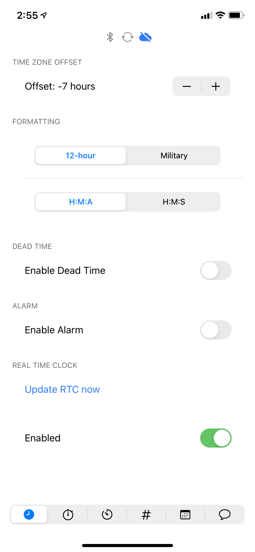
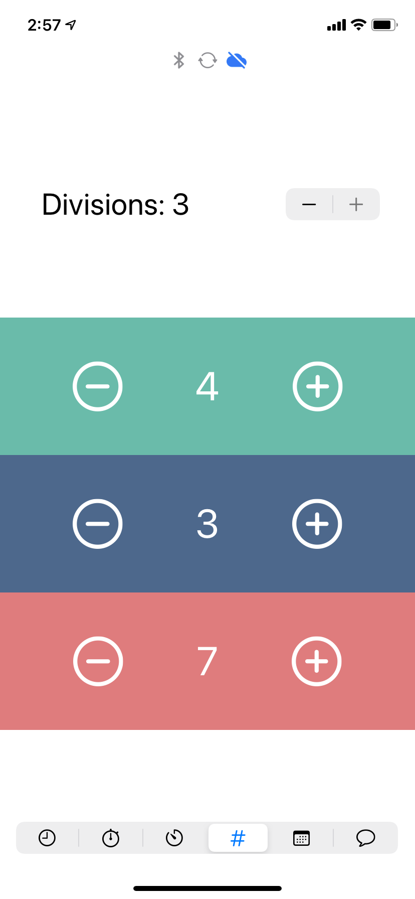
12/21/2020 at 20:44 • 0 commentsThe app took a long time to write, and takes advantage of both Core data and Core Bluetooth. Getting the clock to sync with the app was even harder, and required the use of SPIFFS and ArduinoJSON, as well as a finite state machine to keep track of all of the modes and messages. Here are some screenshots from the app:
![]()
![]()
![]()
-
Testing the Boards
12/21/2020 at 20:42 • 0 commentsHad to develop some initial code to test the performance of the boards, and ended up writing two Arduino libraries, one for one Signalex display and one for Several.
The Chronomix library works with two competing queues to fill up and empty scheduled activations and to fulfill async time demands. When the clock is cleared the state is flushed and better known. It seems to even keep up with a stopwatch!
I got really excited about this step, but wanted some more features, namely phone control and memory, so I went about developing an app for it
-
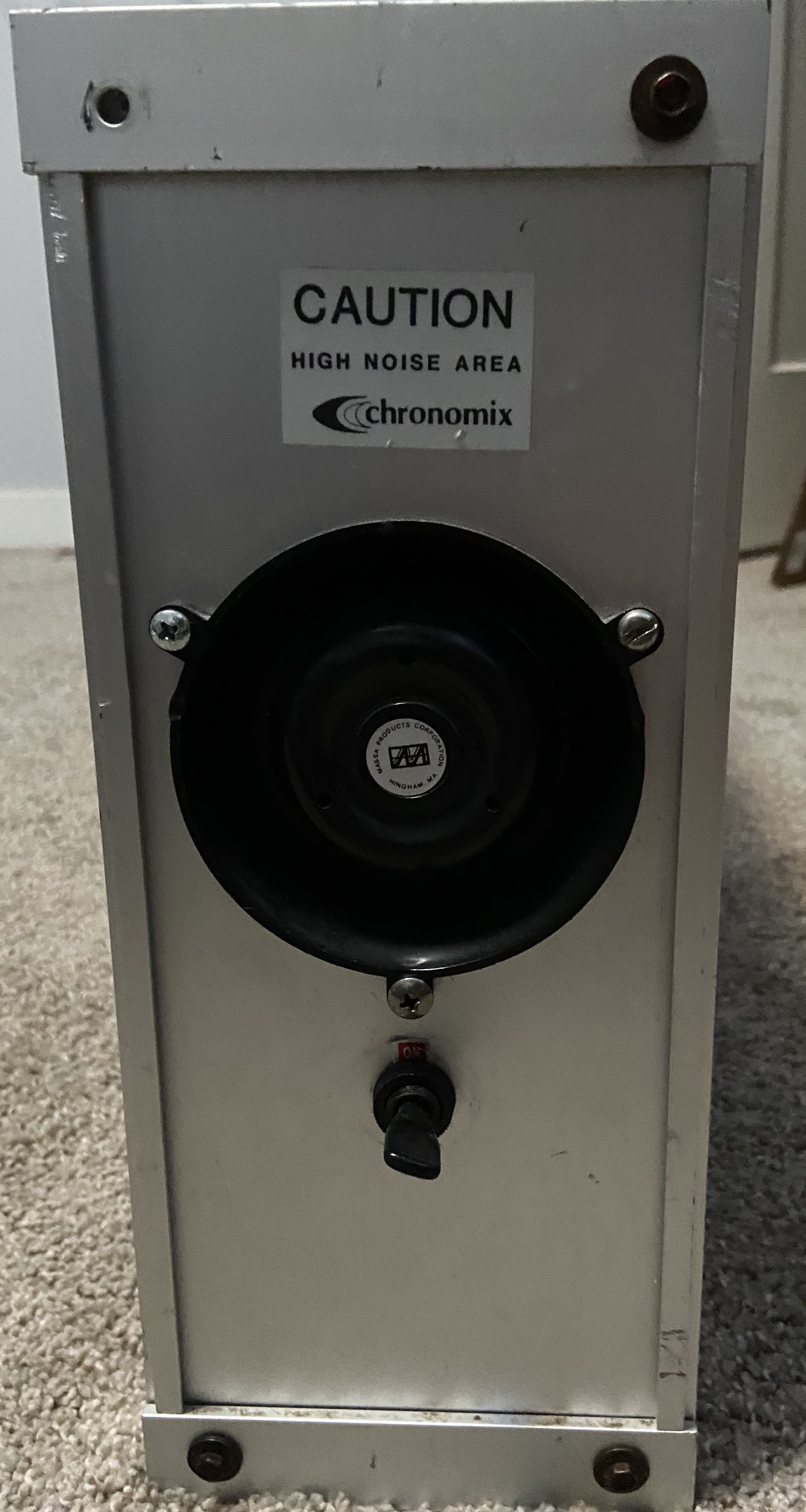
Installing the Boards
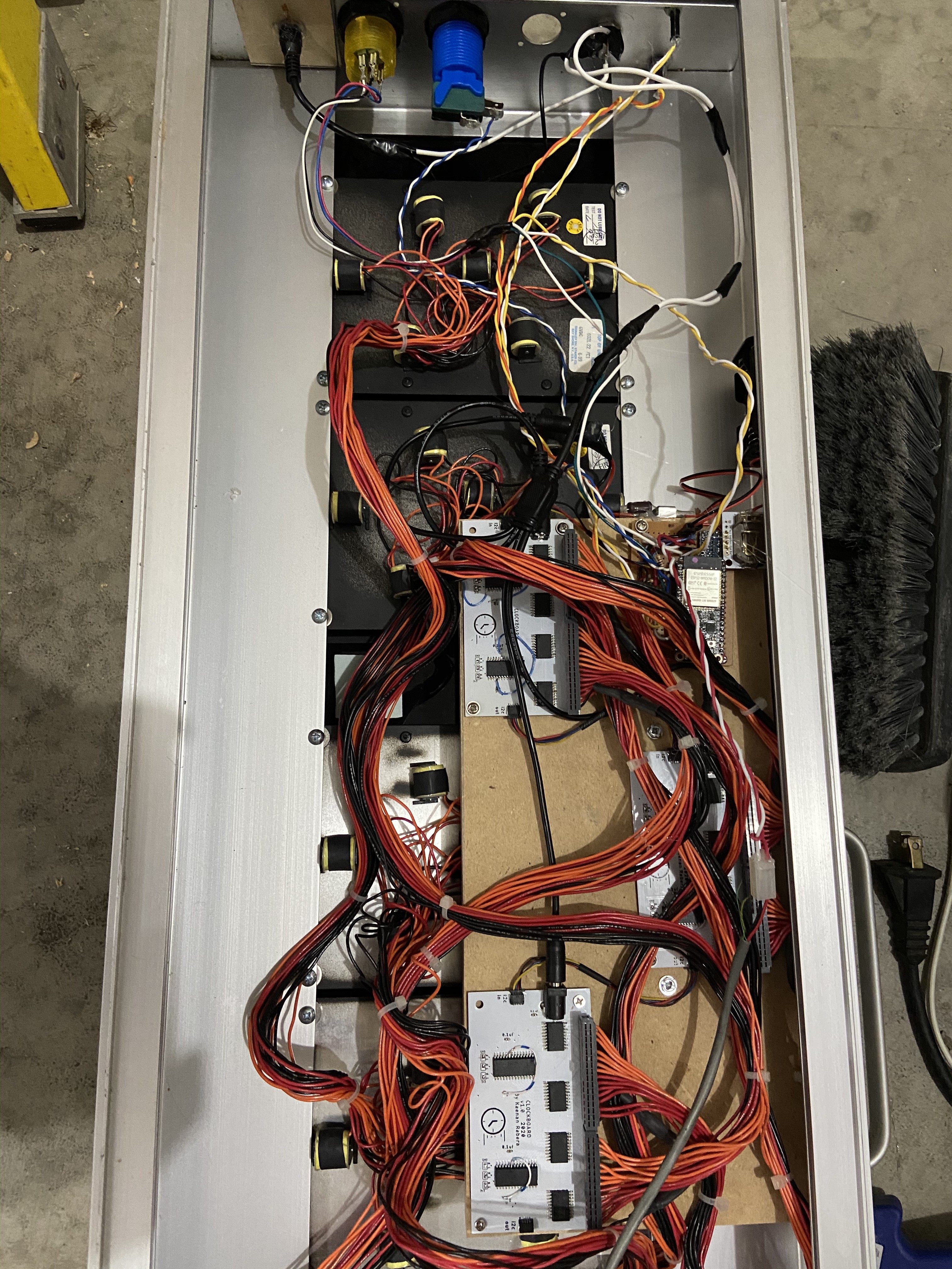
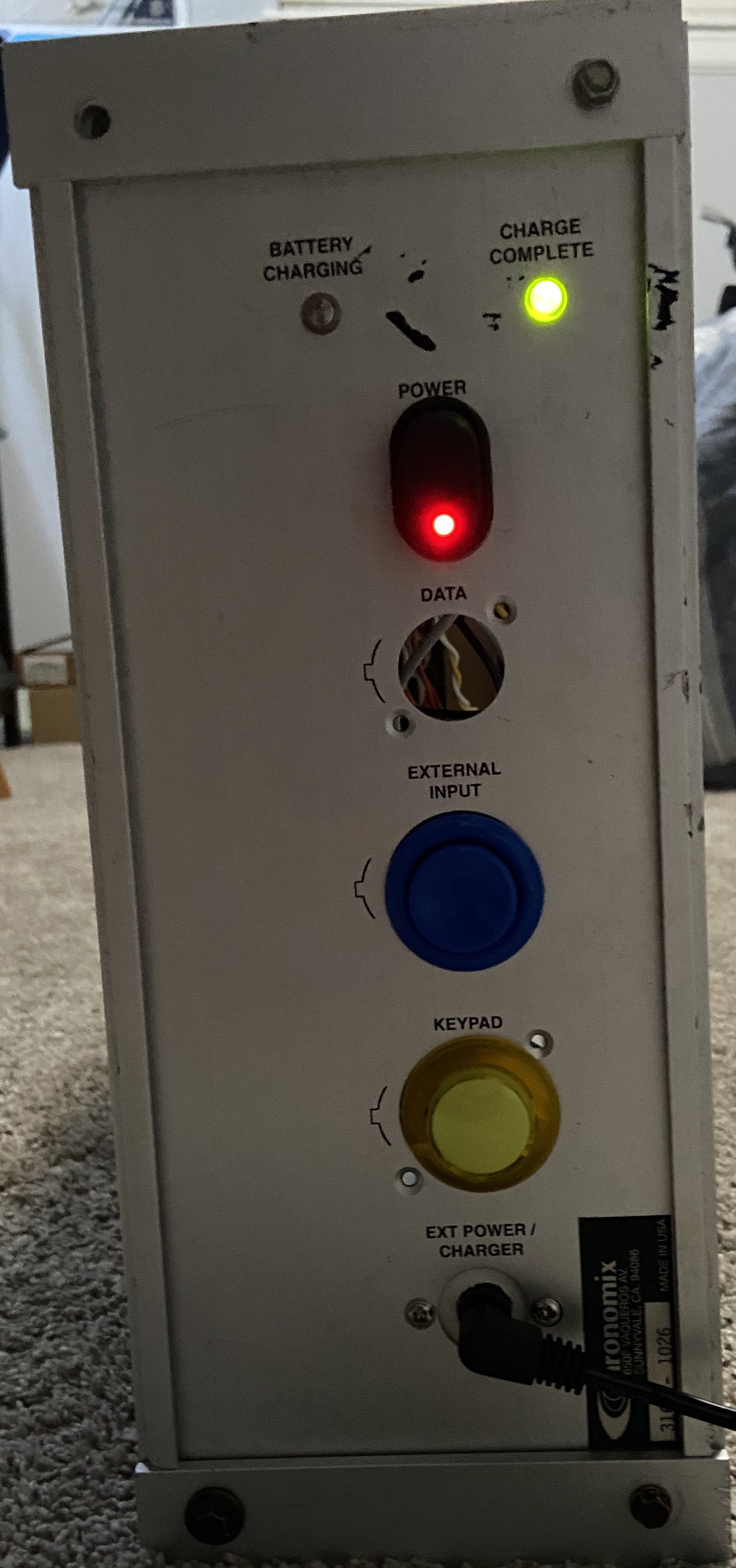
12/21/2020 at 20:32 • 0 commentsI ended up using an ESP32 Feather from Adafruit along with one of their RTC feathers for better time keeping. I tossed in a 5V regulator and a barrel jack splitter in order to provide power to all of the boards out of one jack. After that I modified the case for some basic input and testing, and rigged up the GIANT alarm horn to an NPN transistor in case I ever wanted to use it (it did a short stint as a sound bomb, lovingly dubbed the 'annoyatron')
![]()
![]()
![]()
-
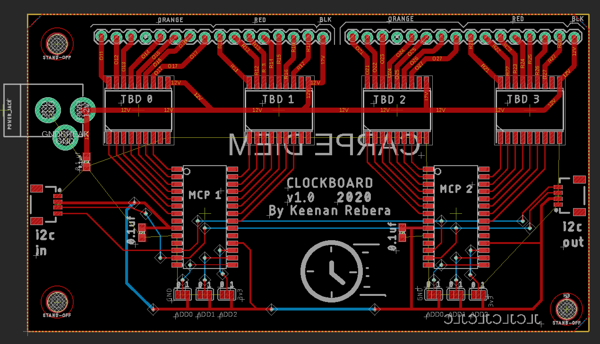
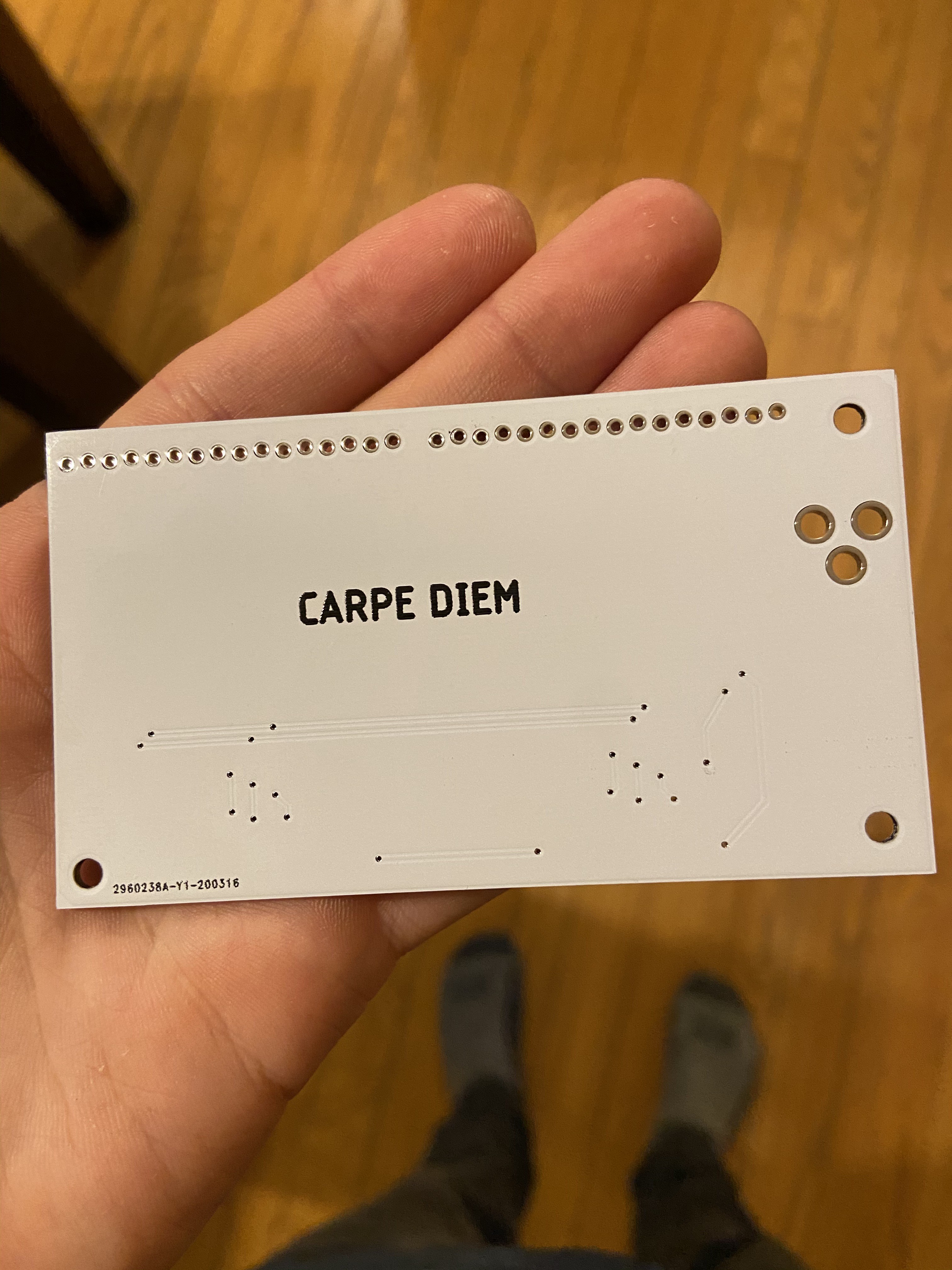
Designing the Board
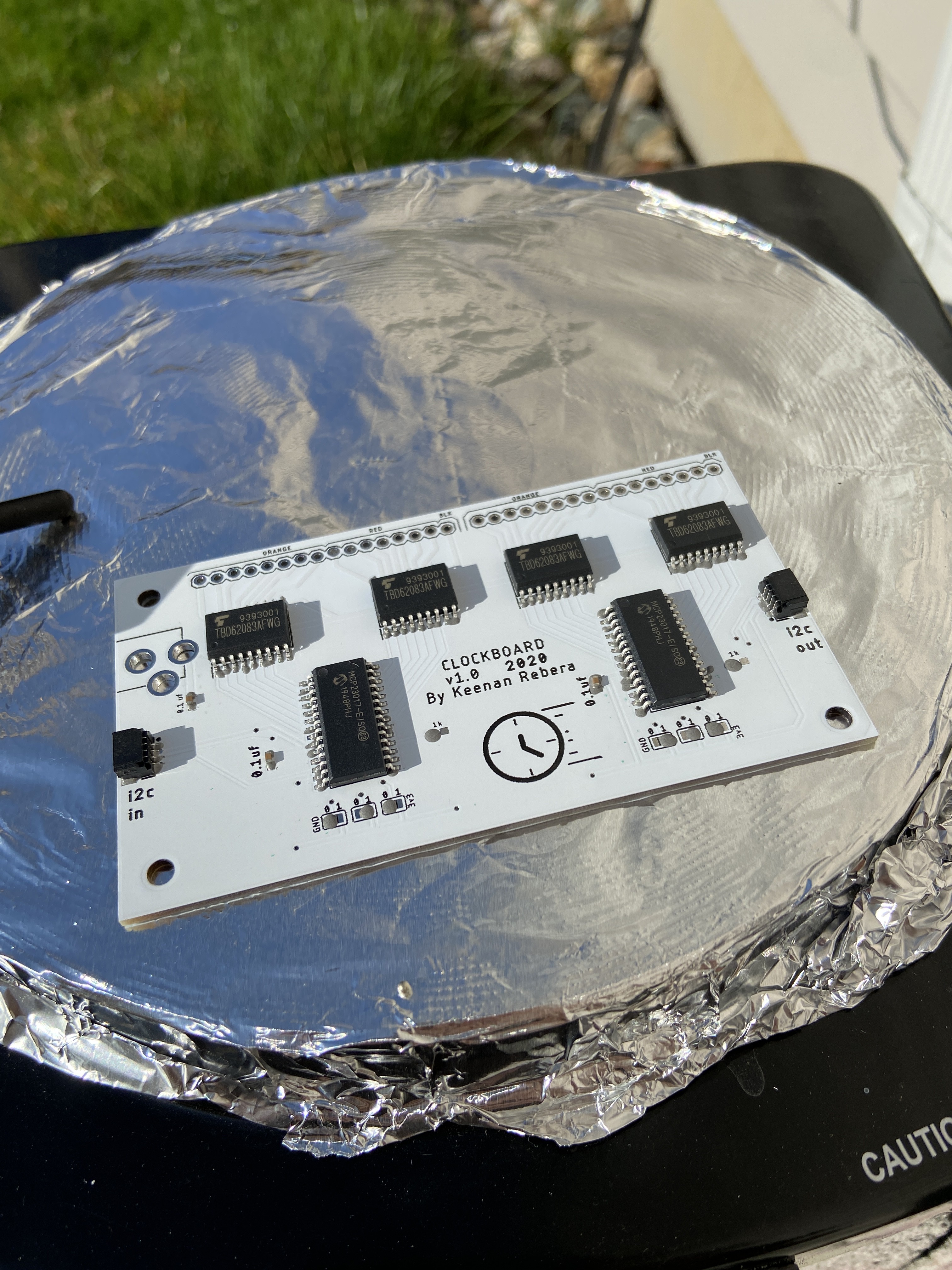
12/21/2020 at 20:10 • 0 commentsI had decided to use the MCP port expander in order to control several of these over I2C when I stumbled upon May Fourth's Sig7Seg design on Tindie. I noticed that she was using the TBD62083 in order to drive the digits, but I wanted a better footprint for mine. I wanted to be able to hot-swap and test the units without soldering the wires right to the board and I wanted to make it compatible with the QWIIC ecosystem. So I designed the board, ordered the parts, and got to work cooking them over a hotplate in the backyard.
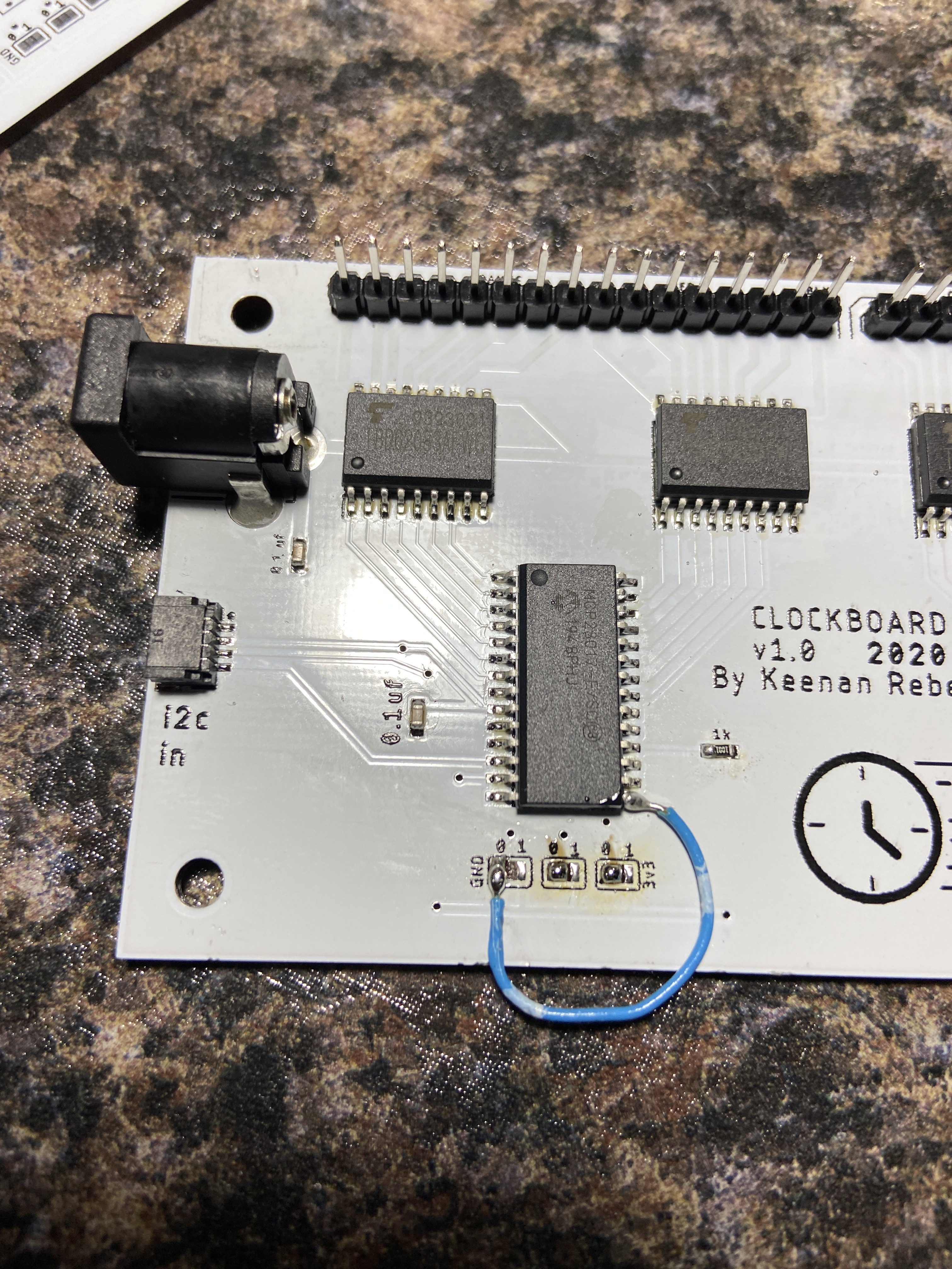
I noticed there was one wiring error in the board, which I have since updated in the design files. It was trivial to fix, however, so I just soldered small wires onto mine instead of reordering the boards.![]()
![]()
![]()
![]()
-
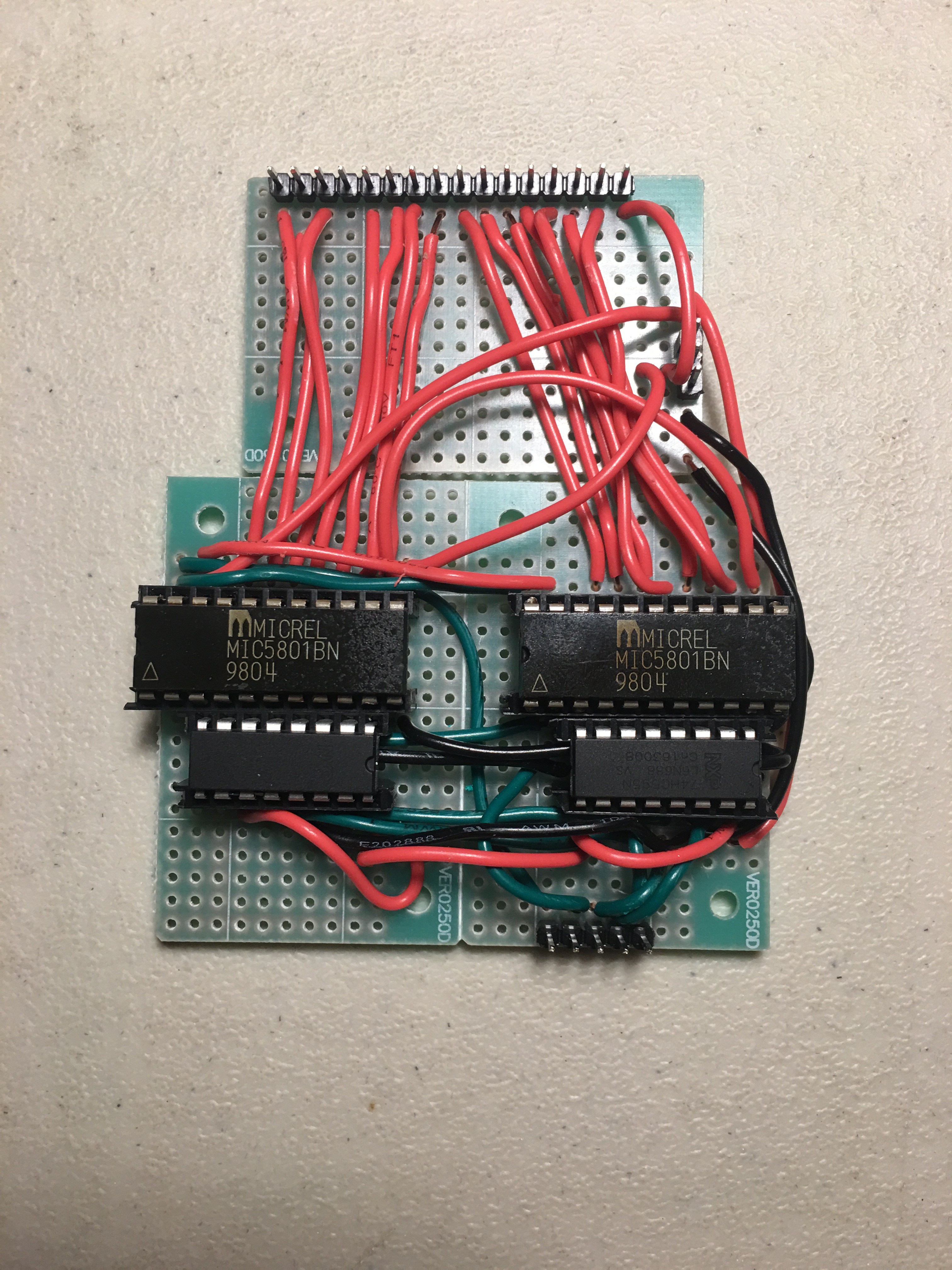
Initial Idea
12/21/2020 at 20:07 • 0 commentsAfter reading the works of Andrew over at Radagast.ca I had it in my head that I would repurpose the 5v drivers that originally came with the motherboard. I took a blowtorch to the poor thing and wired up a test circuit. Unfortunately, it didn't;t work very reliably, and I believe I may have melted most of them. Additionally, a 5v system wasn't a very attractive option to me anyways, so I decided to go about designing my own board for the thing.
![]()
IOT Mechanical Clock with Bluetooth App
Big clock from the 90's overhauled to obey an ESP32 instead of its old motherboard. Lots of possibilities for display. Very clicky.