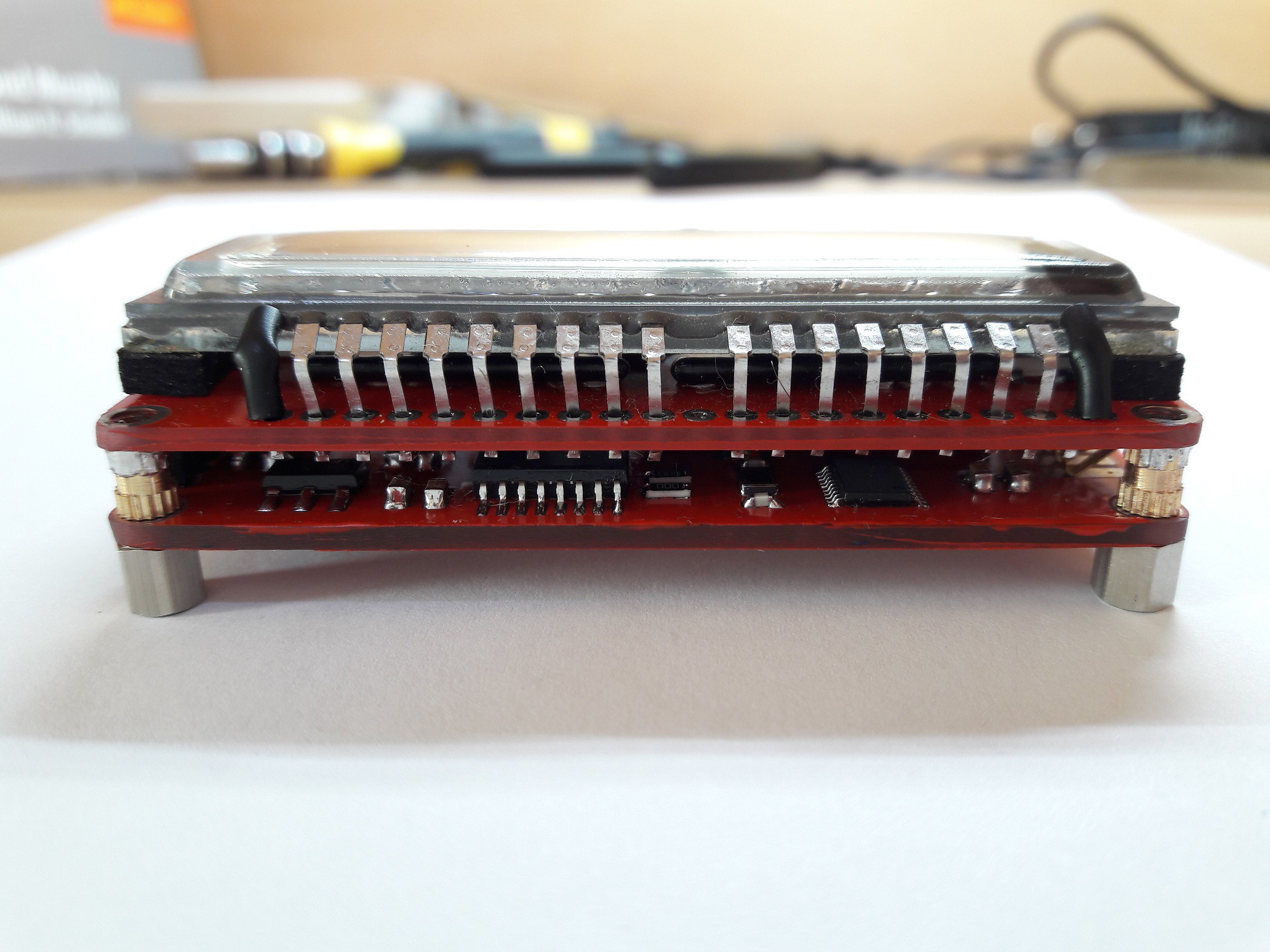
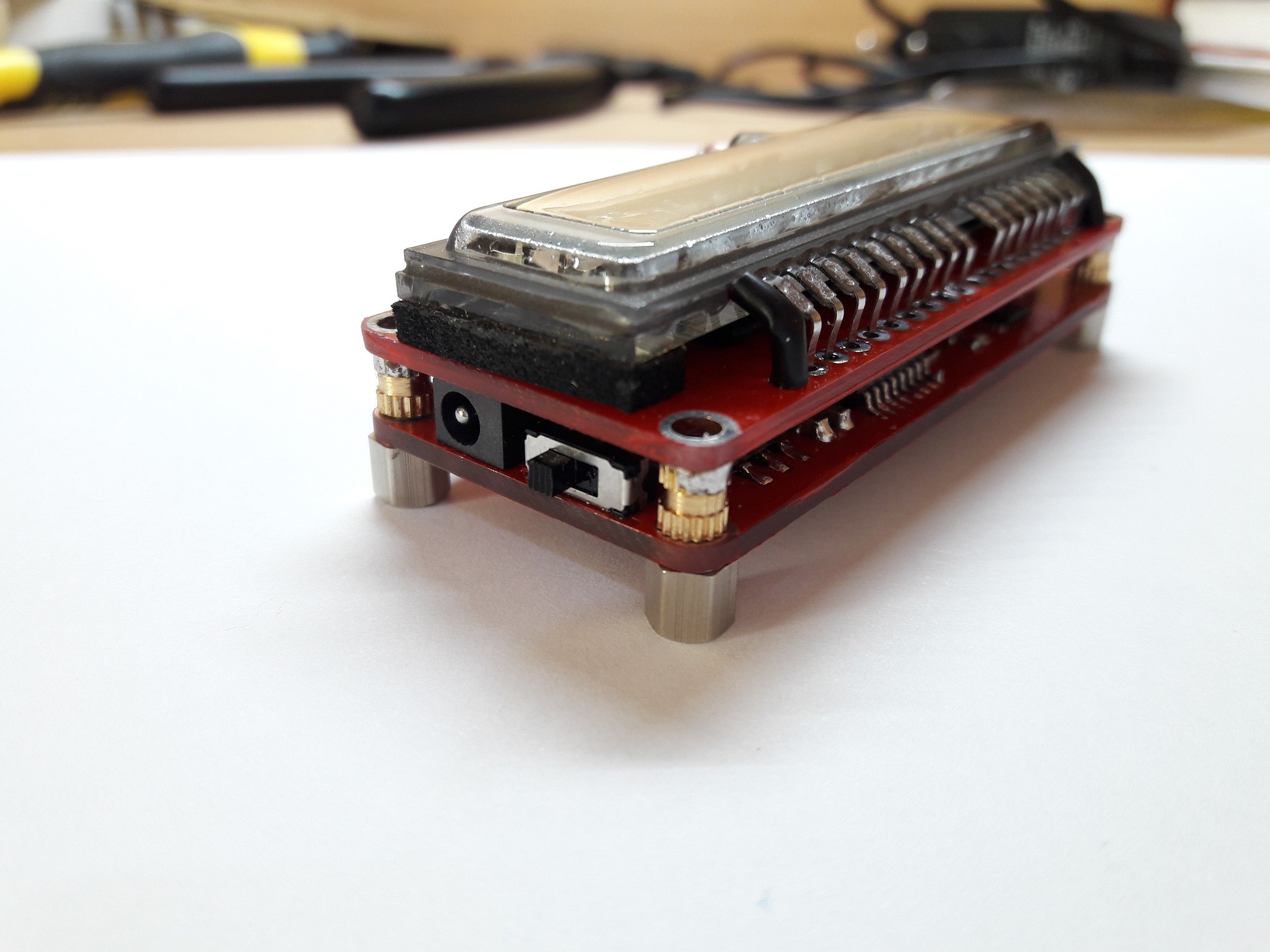
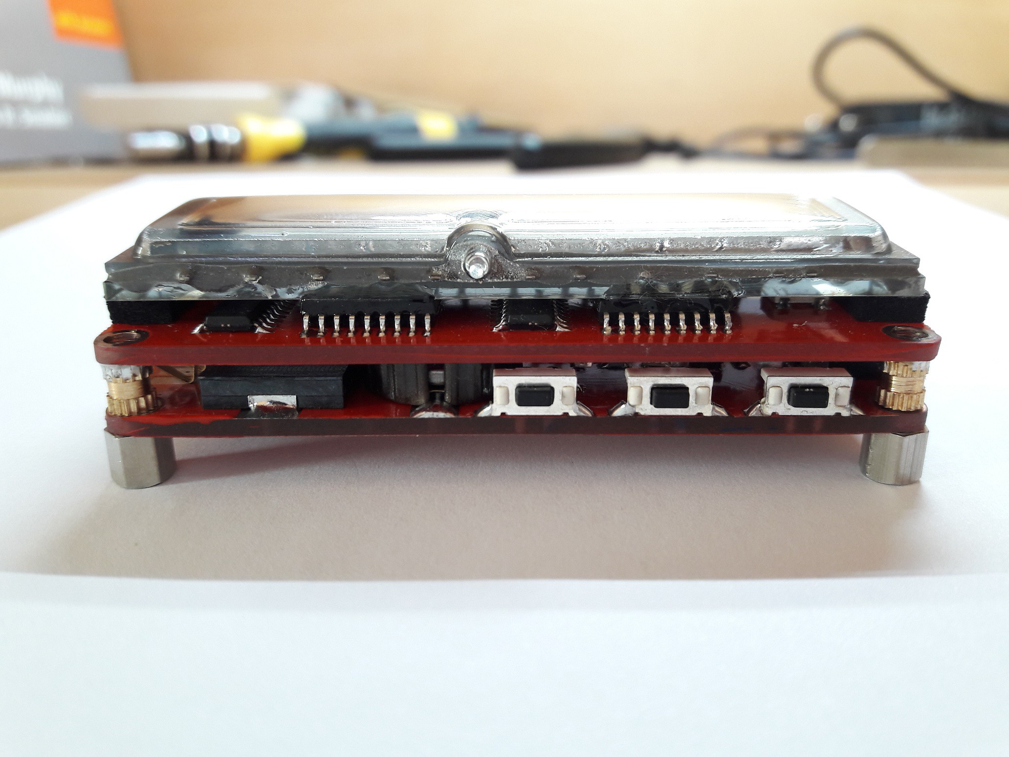
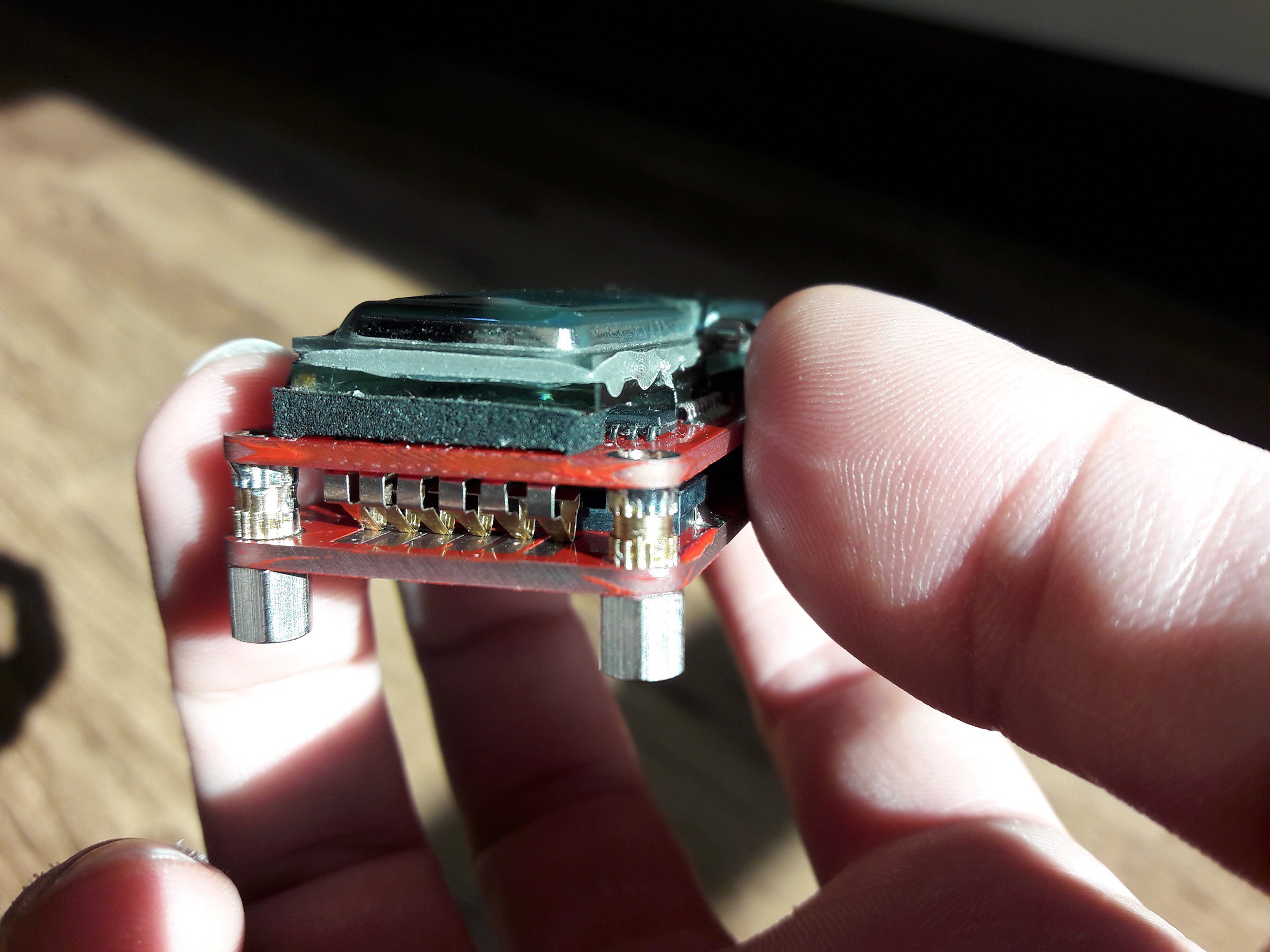
-
Cover
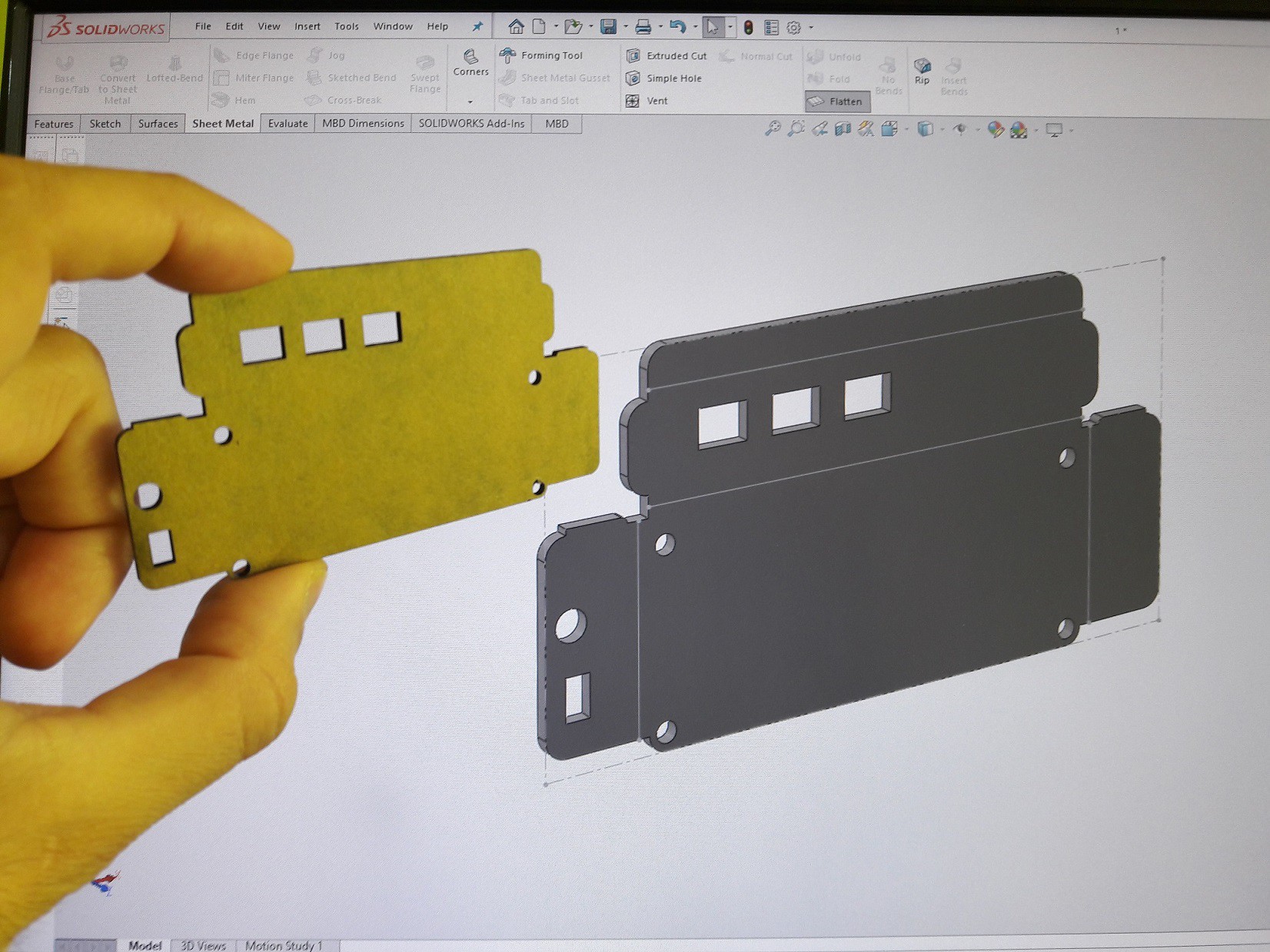
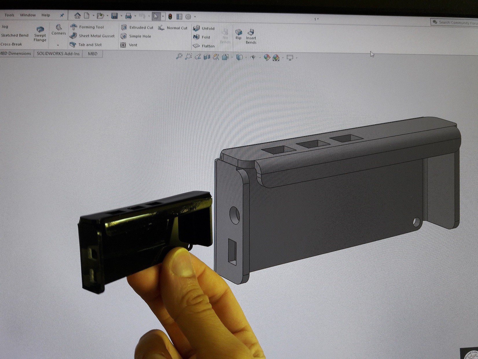
01/02/2021 at 09:16 • 0 commentsI've designed and made a cover for VFD watch...
![]()
![]()
-
Parts come together
12/31/2020 at 09:30 • 0 comments![]()
![]()
![]()
![]()
![]()
![]()
![]()
-
Breakout Board Connector
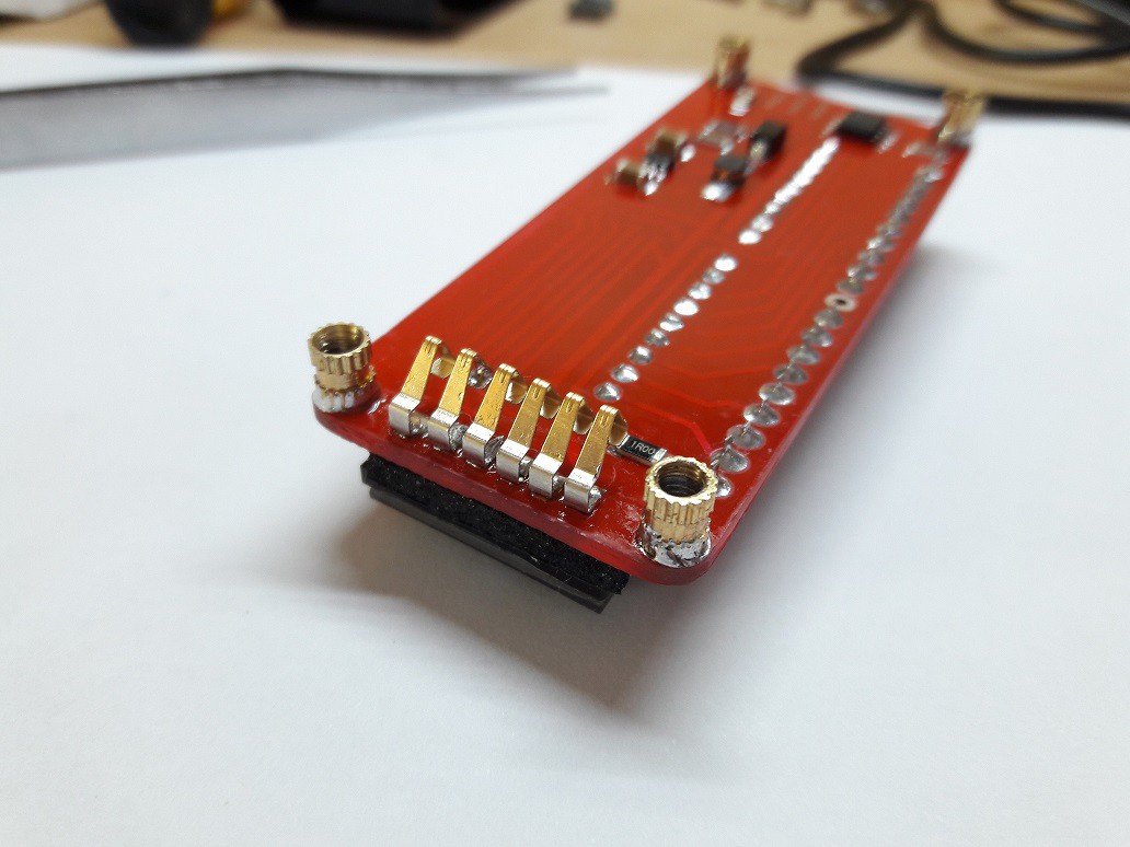
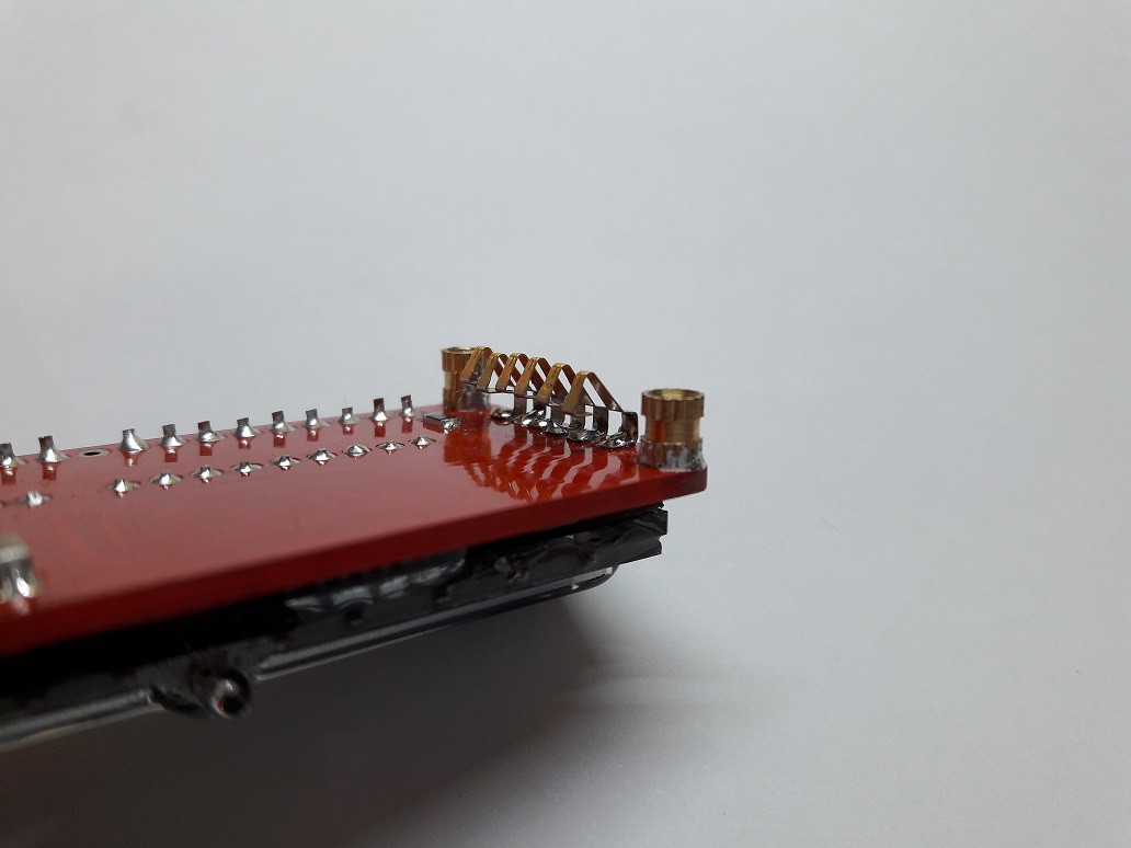
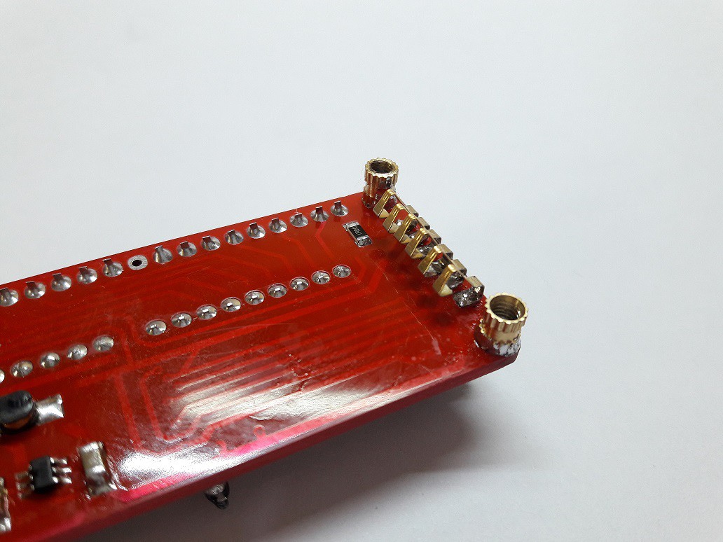
12/31/2020 at 08:25 • 0 commentsUnfortunately i couldn't find a suitable connector for my purpose...So i decided to make it.
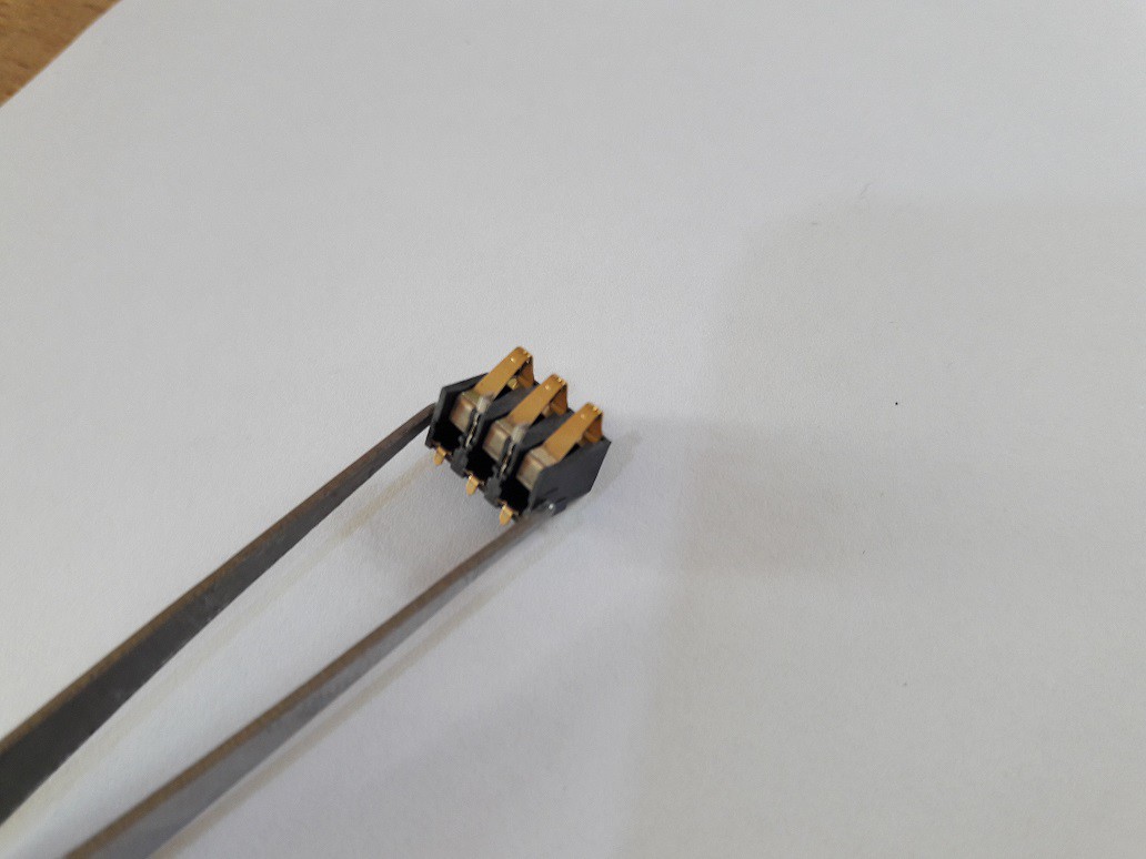
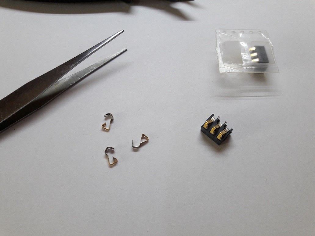
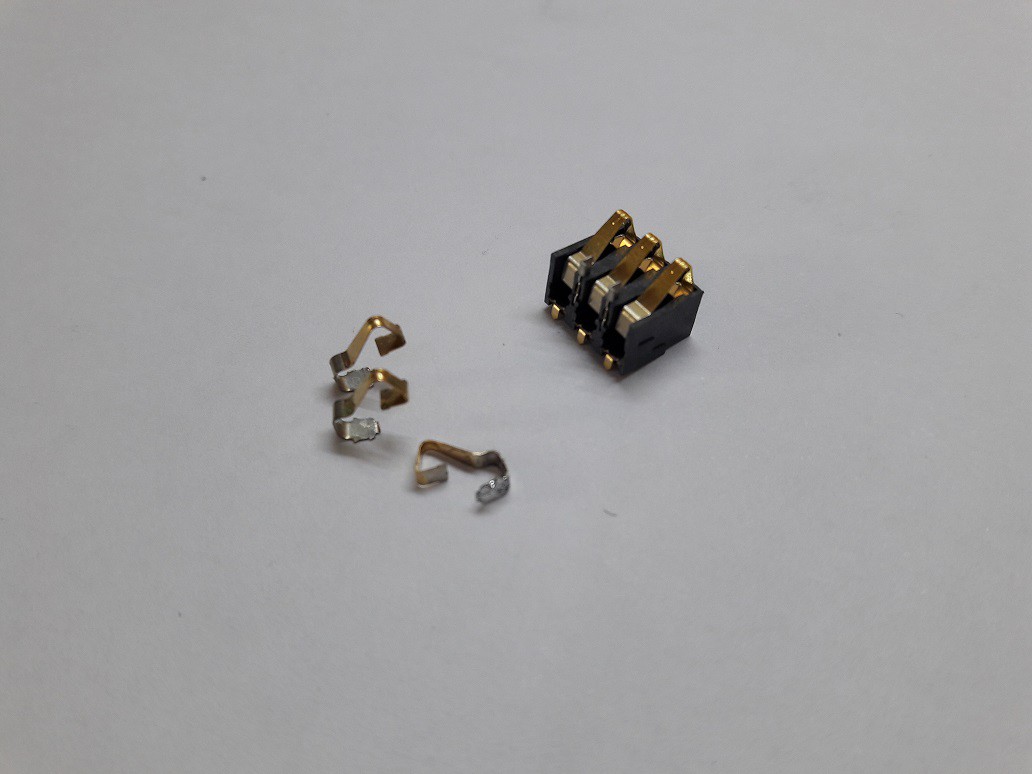
I ordered some Nokia 3110 battery connector to extract their flexible pins.These pins have the exact height that i need.
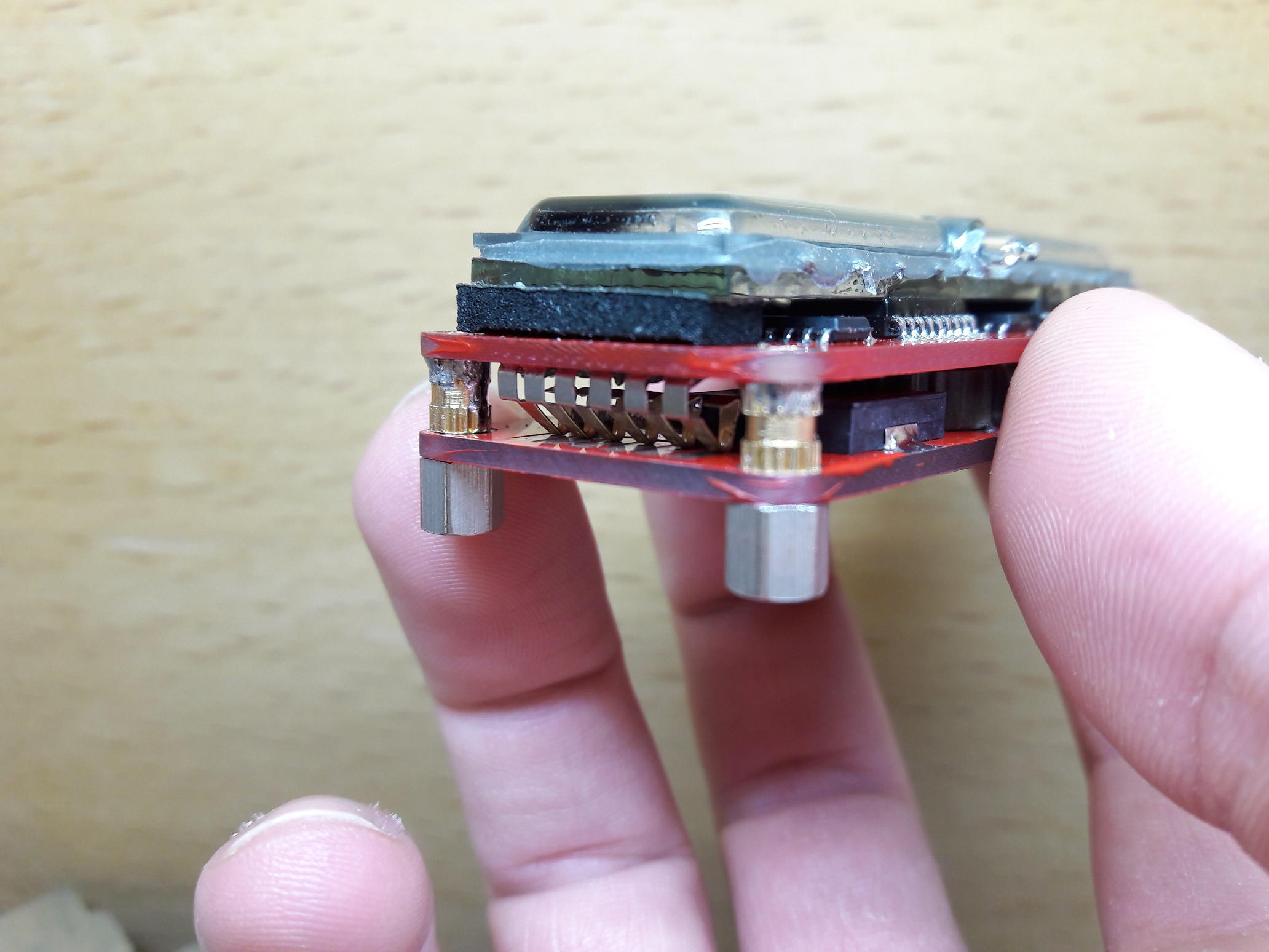
Also, I soldered M3 brass insert nuts as on-board spacer to avoid using extra screws when i'll assemble the parts
![]()
![]()
![]()
![]()
![]()
![]()
-
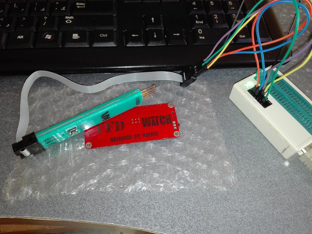
Programming Time
12/31/2020 at 07:43 • 0 comments![]()
![]()
![]()
-
VFD Controller Board
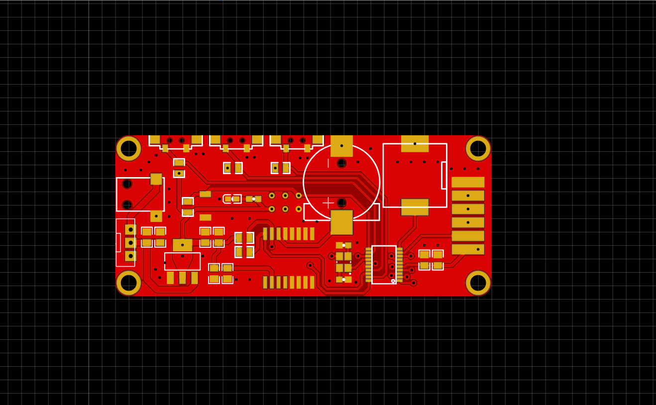
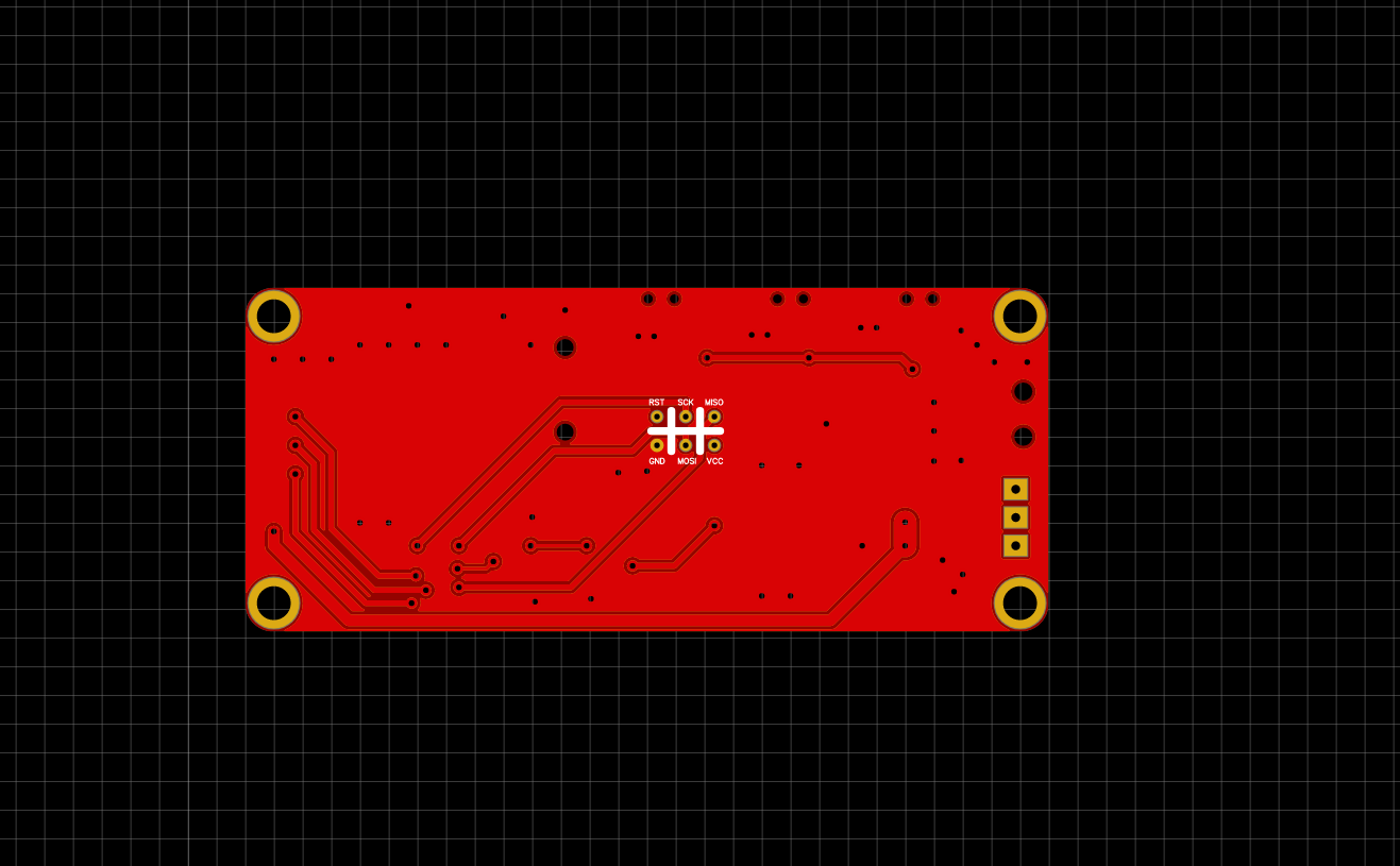
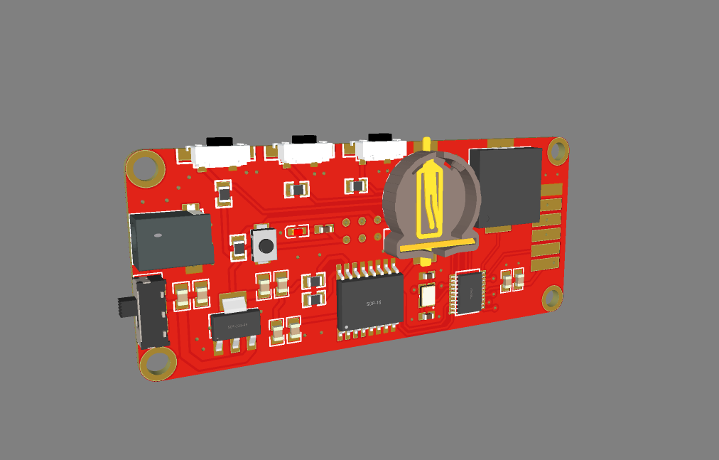
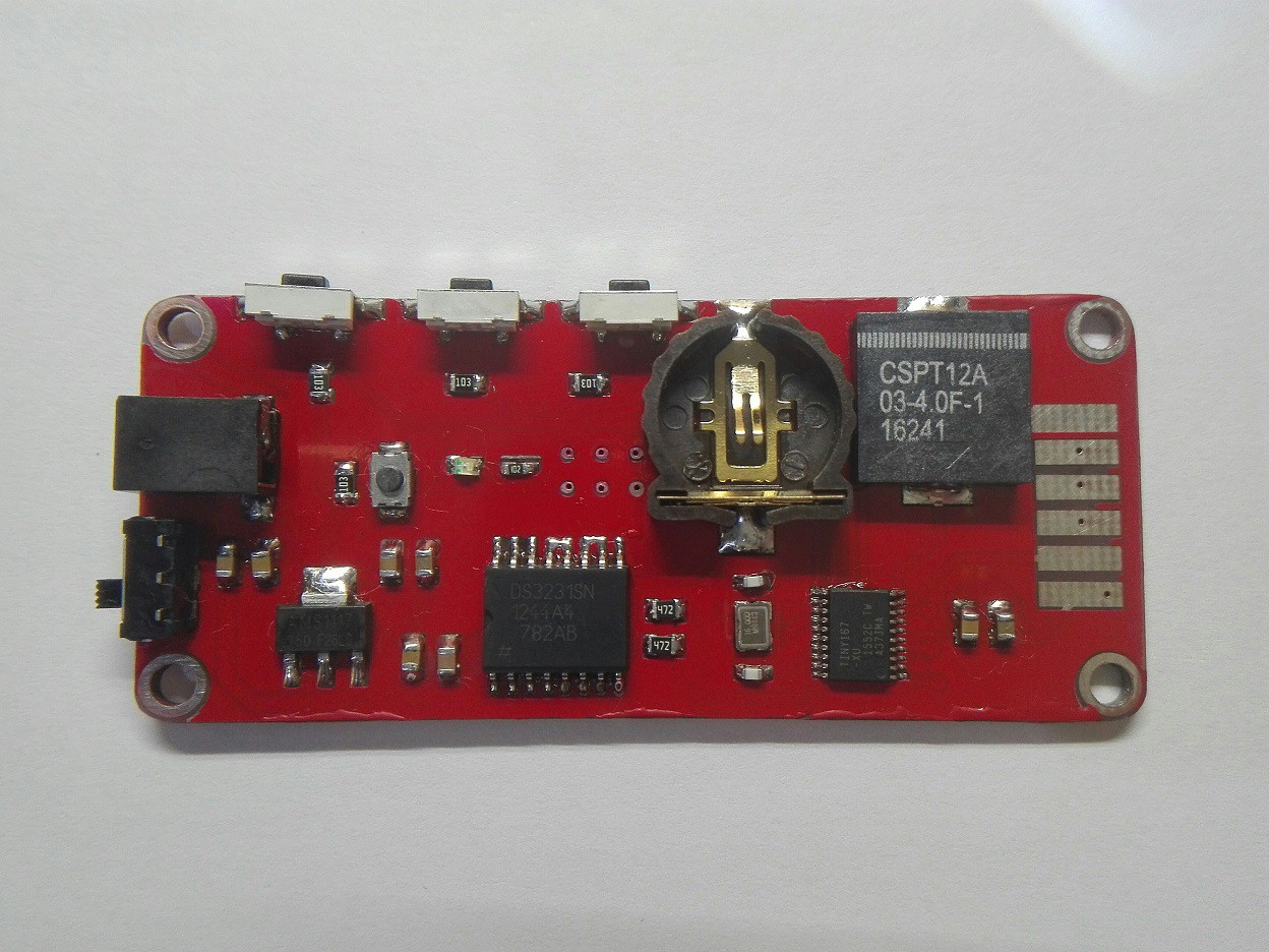
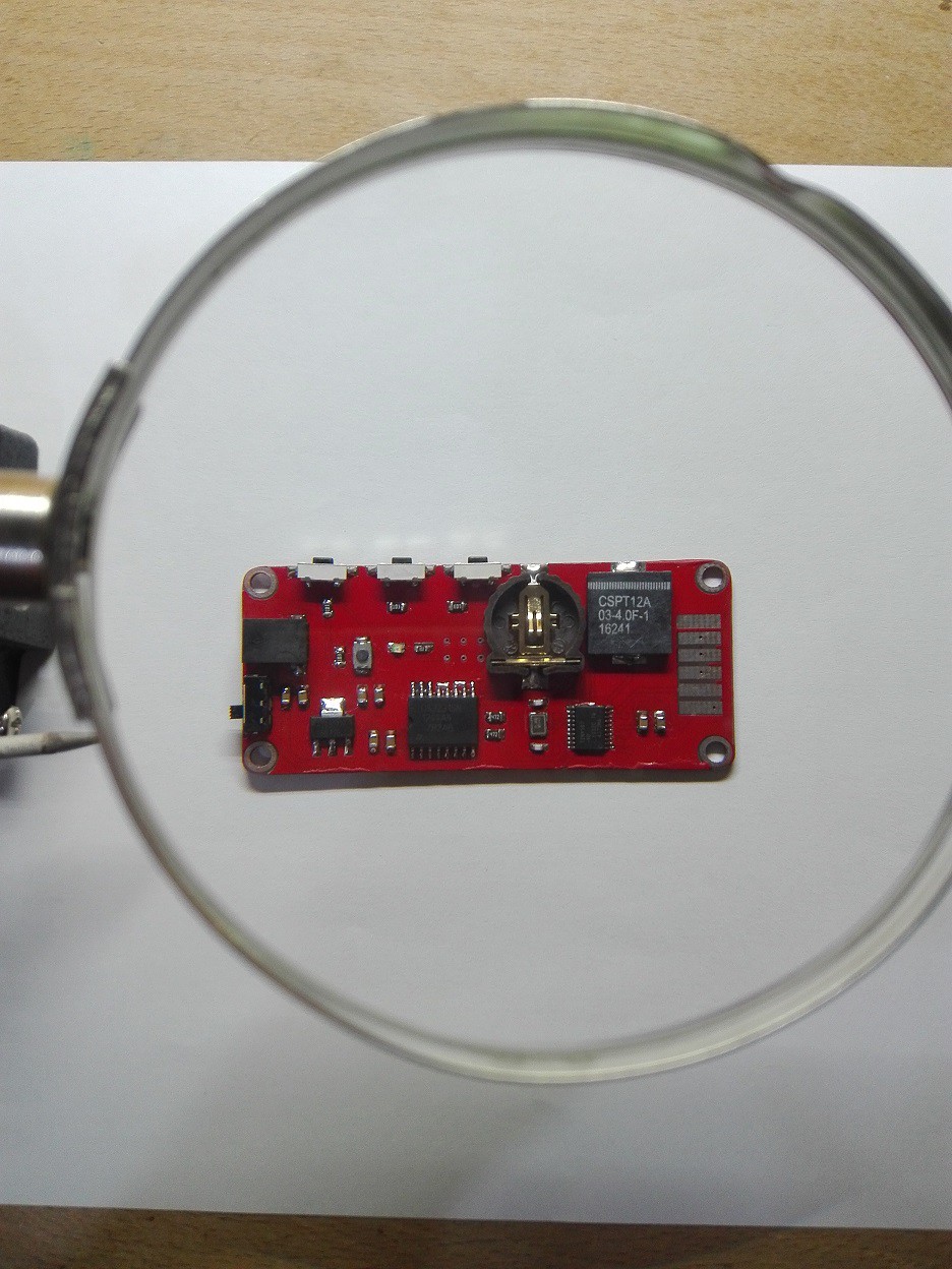
12/28/2020 at 20:51 • 0 commentsThis is the controller board that has a DS3231 RTC chip , an Attiny167 microcontroller , a Buzzer and some other component...
![]()
![]()
![]()
![]()
-
VFD breakout board
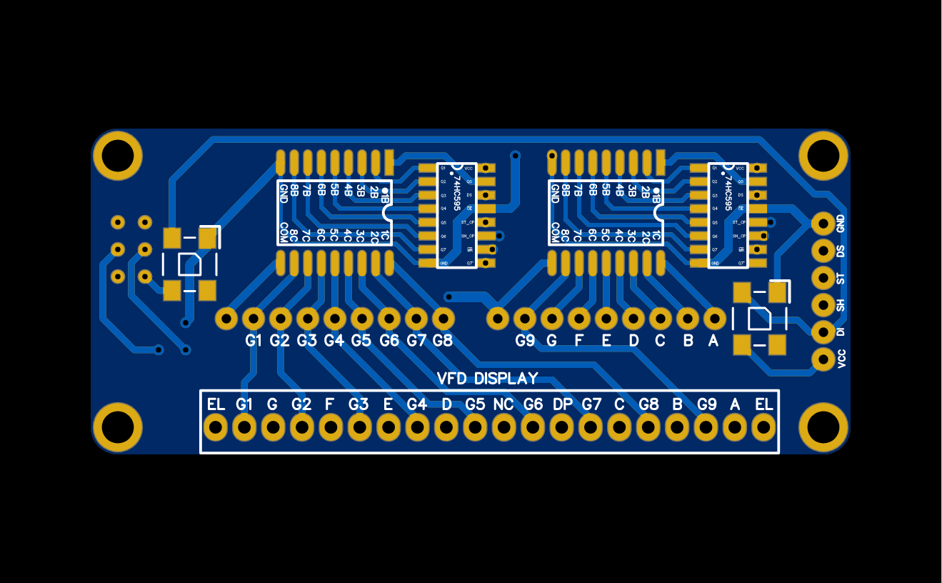
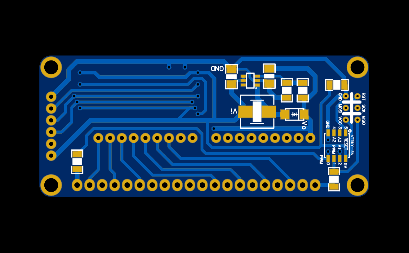
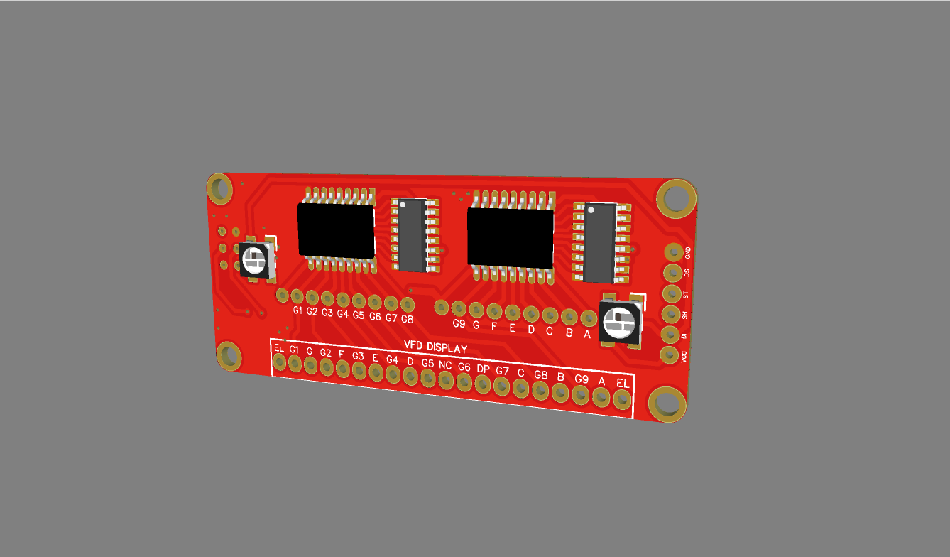
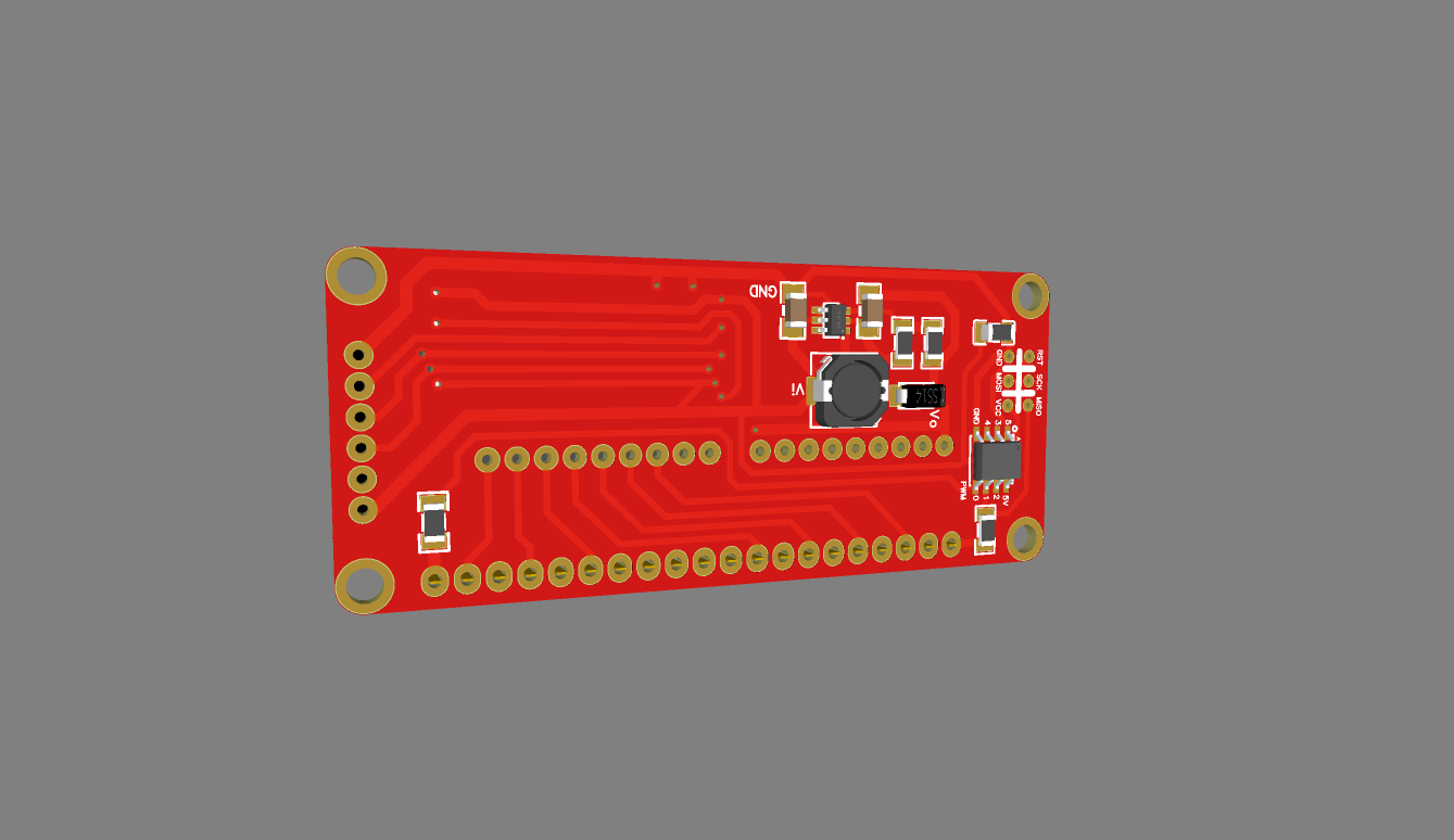
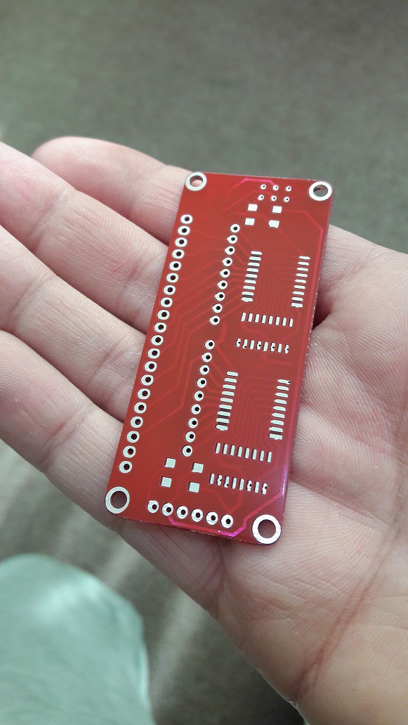
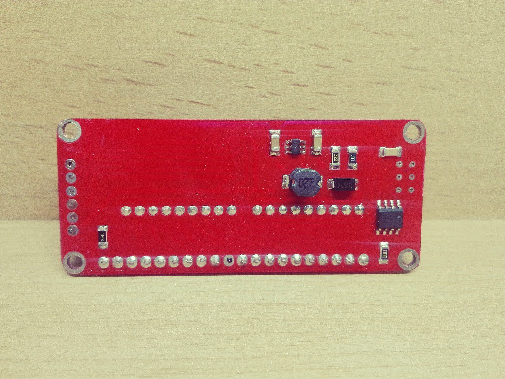
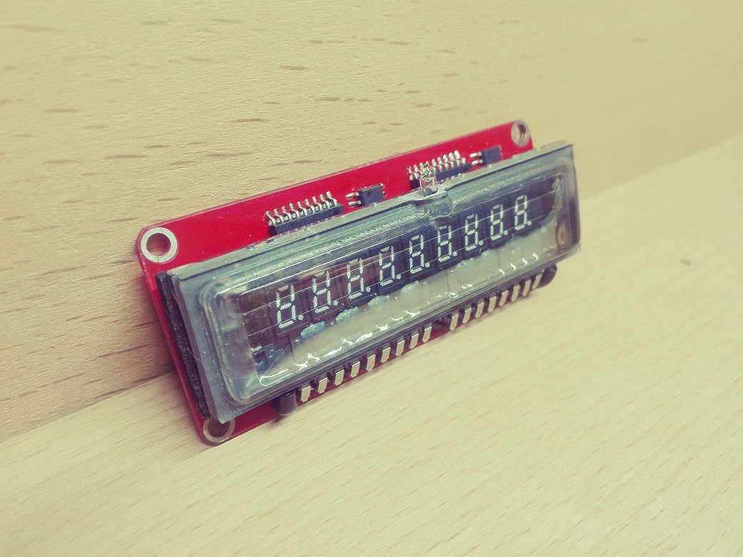
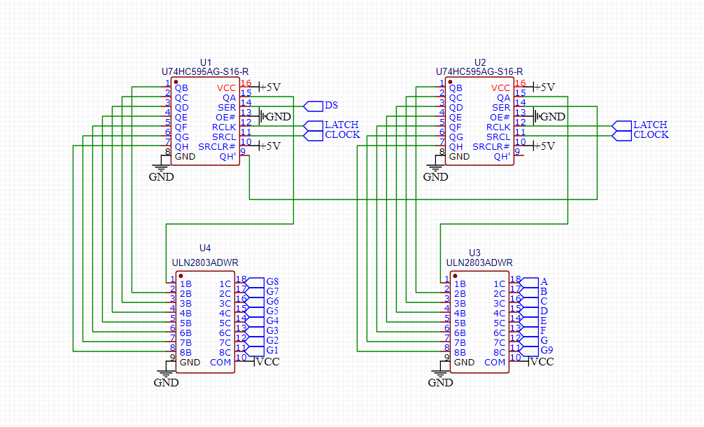
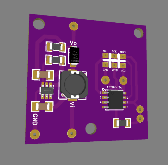
12/24/2020 at 18:06 • 0 commentsI've designed this board for my VFD. it consists of a boost converter based on MT3608 , AC voltage provider with ATTiny13 microcontroller , ULN2803 and 74HC595 ICs to control all grids and segments with 3 pins and also has two ws2812b RGB led as backlight especially used in alarm clock feature.
![]()
![]()
![]()
![]()
-
VFD controling method
12/24/2020 at 16:19 • 0 commentsI used combination of ULN2803 and 74HC595 to control all VFD just using 3 pins.
-
MT3608 & ATTiny13 test PCB
12/24/2020 at 15:57 • 0 commentsTesting boost voltage circuit with fixed output voltage also program and test Attiny13 to provide a 5v ac voltage for VFD filament.
-
Filament AC voltage
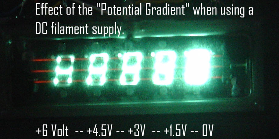
12/24/2020 at 15:51 • 0 commentsFor filament we can use DC or AC voltage but AC has superiority over DC. If the filament is driven with a DC voltage there will be a voltage gradient across its length. This means the end of the display with the more positive filament voltage will have less of a differential to the anodes, and thus will be dimmer than the negative end of the filament due to the potential gradient effect.
![]()
http://insanity4004.blogspot.com/2017/03/p170-dh-vacuum-flourescent-display.html
https://www.qsl.net/m0ayf/VFD-Regen.html
to producing AC voltage i decided to use a microcontroller, in this case i choose an Attiny13 .
for achieving a 5v 60hz ac voltage i programmed two pins of Attiny13 as output and switching them on/off respectively with a 8 milliseconds delay.
void setup() { pinMode(0, OUTPUT); pinMode(1, OUTPUT); } void loop() { digitalWrite(0, HIGH); digitalWrite(1, LOW); delay(8); digitalWrite(0, LOW); digitalWrite(1, HIGH); delay(8); } -
MT3608 circuit test pcb
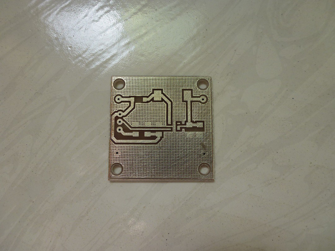
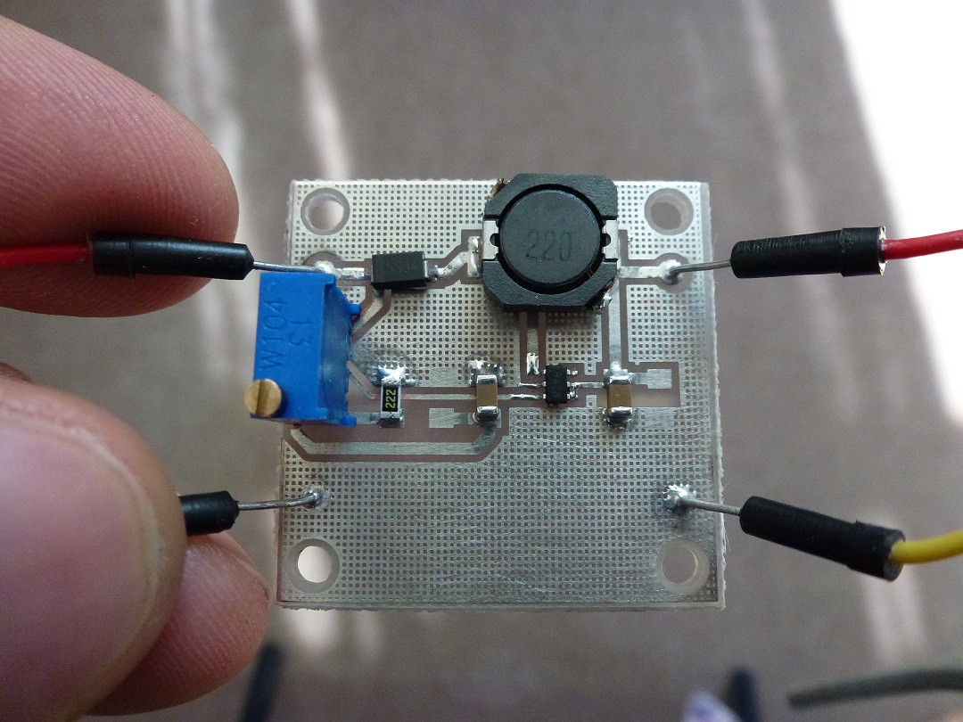
12/24/2020 at 14:22 • 0 commentsIt works fine and boost 5v up to 28v
 Ben Mo