 John Duffy
Some inevitable changes have come up during layout.
Biggest changes have all been for size - between the volt and ohm protection, two fuses, input module, that I've got less "vertical' room to work with (since the display is separate), and all the big through-hole modular parts (ADC, Pi Pico, radio modules), space is REALLY tight. I've changed the shift registers from SOIC to a tiny QFN package, and cut a whole bunch of caps and changed the resistors in the voltage frontend to make layout of that section easier.
I've also ditched having the PGA/MUX as a modular component - it just doesn't really seem that useful to change that up. If I've got room in layout I may copy some of the signals to some unused pins on the ADC module - that way if the PGA is limiting in some way in the future it can just be de-populated, and a replacement integrated directly onto the ADC module. I also realized that going to an MCP3464 may not be a terrible idea - these have some analog gain built into them so with that I could potentially skip the separate PGA/MUX chip entirely.
I may have to change to SMD header pins for either the ADC or pico. I like having regular-size pin header holes for as many things as possible since they're so versatile, but if I don't have enough space to route all this there may not be another option.
Either way here's where it's at now:
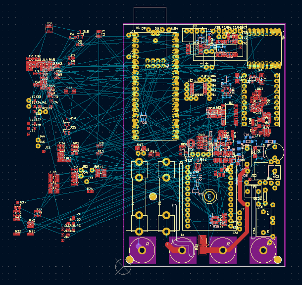
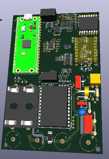
I don't currently have any regular CAD software so can't make models for the non-standard parts. Namely the fuse holders on the left are just the end clips, the super-wide "DIP chip" in the middle is standing in for the input module, same for the RFM radio in the upper right,. The ADC module is just a light orange box in the middle on the right. I'll probably have to finally give in to one of those free cloud-based ones for this eventually to do the case
Discussions
Become a Hackaday.io Member
Create an account to leave a comment. Already have an account? Log In.