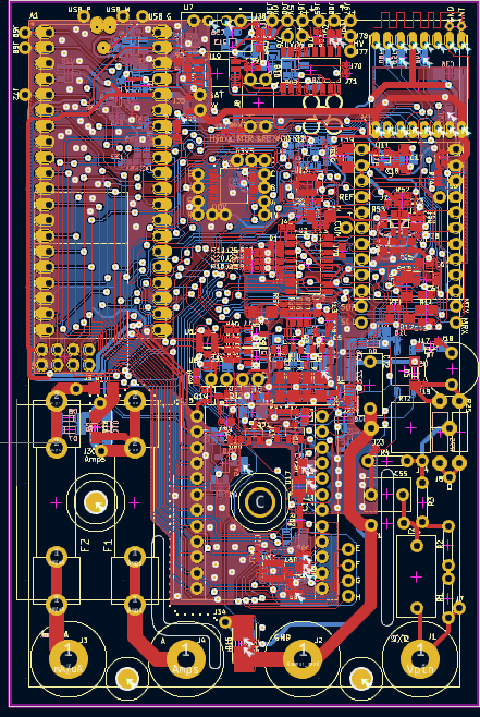
Finally finished layout, this ended up being a huge pain though and I'm not super happy with it.

Very dense in some places but empty in others.
Mostly the SPI/I2C/Uart busses going to the input module, ADC, PGA, and radios, and shift registers. I'm very not happy with the lack of good separation between the analog and digital, and that I wasn't able to get solid ground planes under all the analog lines. Whole lot of lessons learned but I want to get this out the door already to get *something* together so I can learn all the OTHER ways I screwed it up and can fix them in one go.
Couple big ones:
-Having modules on through-hole 0.1" headers makes things a huge pain. They take up a ton of board space on both layers, so I have to plan on routing around them. In future I'll probably use SMD header pins.
-Pi Pico form factor for the MCU wasn't really the way to do it. Should have had an adapter board and move some of the digital stuff like shift registers to that.
-Should have made the isolated coms a separate module as well.
-Having two separate radios was dumb. Have one, and adapter boards to whatever commodity radios I want.
-Plan placement with wide digital busses in mind. I kind of did but it was insufficient, there were a ton of little pinch points where I had to go all over the place. Also having all the modules spread out meant those busses had to go all the way across and up and down the board instead of being kept short. I originally placed to keep analog lines short, the ohms and volts sections are right next to the low voltage side of the input protection, and the PGA and ADC are right there in the middle as well. I'll probably see more problems from having to route big fast digital busses nearby than if I'd had slightly longer analog lines but good separation.
Any case I'm going to make some of the other little boards I need and get this sent out soon.
Moving on to mechanical design now. I found out solidedge has a free, non-cloud version and is related to NX (which I'm already familiar with from work). Started using that but there's a bunch of weird annoying things about it, like just now I've spent an hour trying to make a simple linear pattern in an assembly. Yeah turns out you can't, you have to make a sketch with a pattern of something, then make a pattern from that sketch. WHY?! NX supports doing this the normal way, why mess with it?
Anyway I'm starting that, should be fairly straightforward, it's pretty much just a box with some holes in it for the connectors and stuff.
 John Duffy
Discussions
Become a Hackaday.io Member
Create an account to leave a comment. Already have an account? Log In.