-
1Build a datapak connector for the breadboard
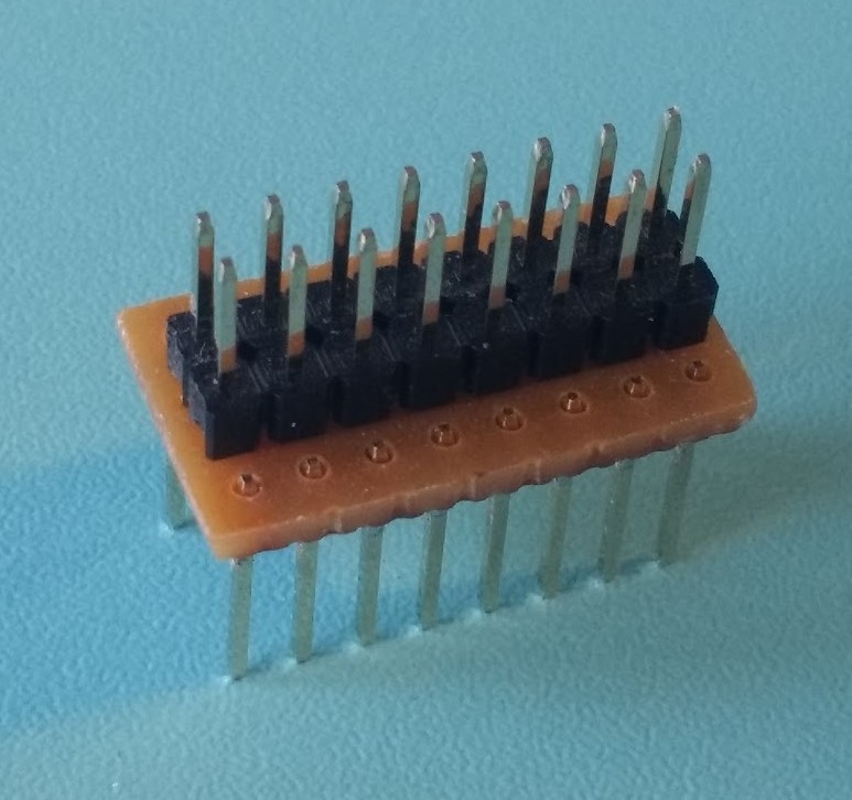
Make a datapak connector for the breadboard, it just widens the pin spacing to fit over the centre gap of the breadboard.
![]()
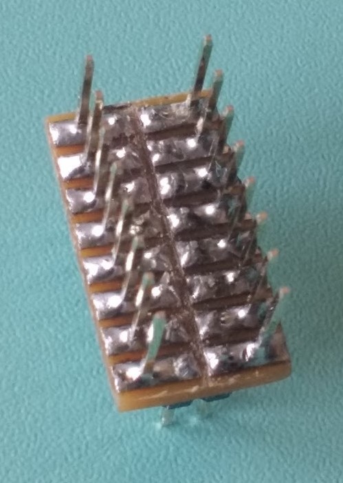
The lower pins were pushed through the plastic to make them longer for soldering and the plastic was removed afterwards. If you use stripboard, be sure to cut the tracks on the centre line to prevent a short:
![]()
-
2Wire up the connector to the Arduino
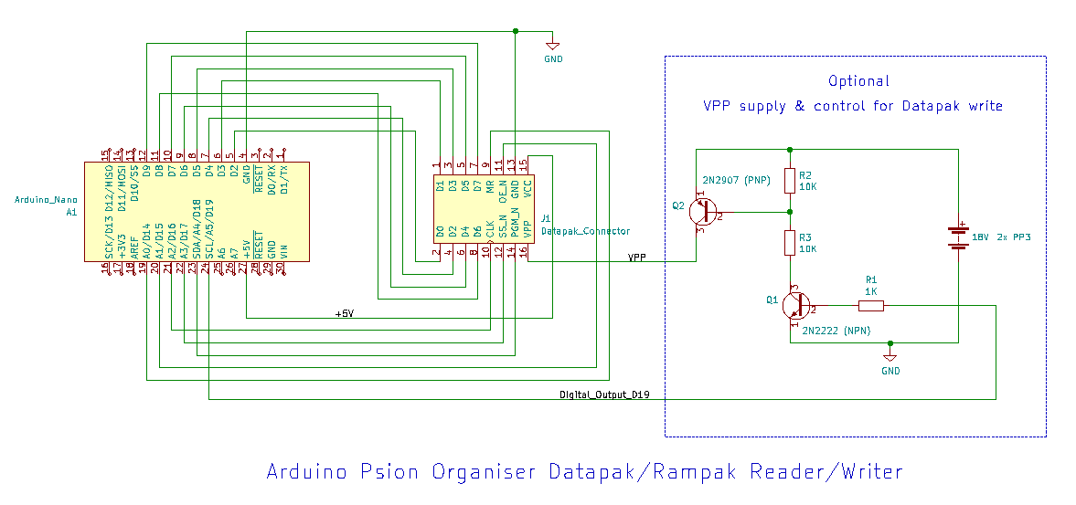
Insert the Arduino Nano into a breadboard and connect to the datapak connector as shown in this schematic:
Add the optional VPP supply & control if you want to write data to a Datapak (not required for Rampaks). R1 limits the current load of the Arduino digital output (D19), Q1 (NPN) pulls the base of Q2 (PNP) low when the Arduino output goes high. R3 limits the current from Q2 emitter-base to Q1 collector-emitter. R2 is a pullup to keep Q2 in the off state until Q1 pulls low. The supply is 2x 9 V PP3 batteries. A zener diode reference in the datapak reduces VPP to the correct voltage for the EPROM, typically about 13 V.
-
3Install the software
Upload software to the Arduino, and run the Python software on the PC. The Python software requires 4 libraries: serial, keyboard, time and os, you may need to install these first using pip (or conda if using the Anaconda distribution of Python).
The software can be found at my Github page: Github Psion2 pack reader-writer
-
4Connect a Datapak or Rampack
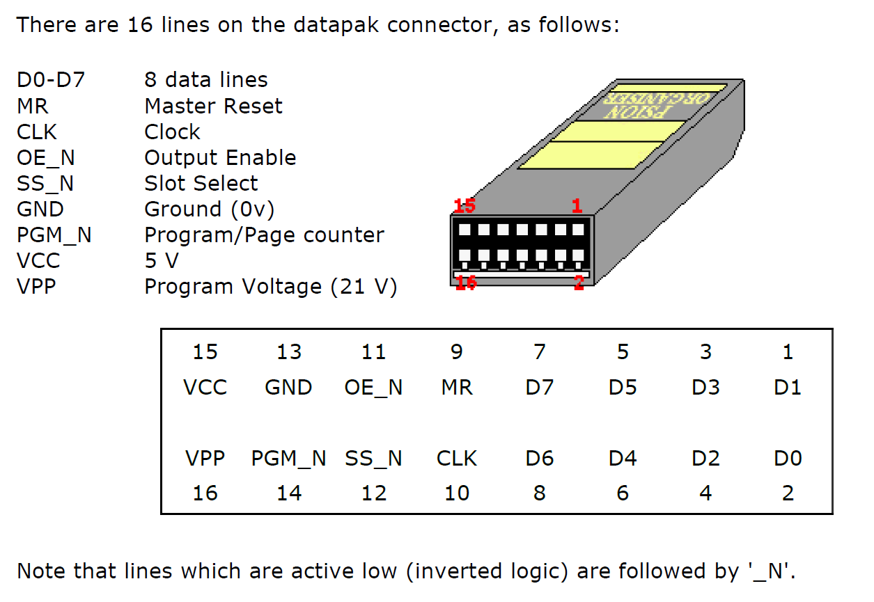
Make sure you connect the pack the correct way around (see the datapak/rampak pinout below, also if you unclip the cover of the datapak/rampak some of these packs have pin 1 indicated by a red triangle) and only insert or remove a pack when prompted by the software. Select datapak or rampak mode using the 'm' command.
-
5Start reading and writing pack images
The software presents the user with a simple text menu of options. Sending a single character via the serial link will select the command. Some of these commands can be used via the Arduino serial monitor, or similar terminal, but the read and write commands expect the data to be echoed back to verify it and control data flow, this is coded into the software. Filenames for pack image transfer are entered directly into the Python code before it is run using the infile and outfile variables near the top of the program listing.
Description of the the commands:
- e - (rampaks only) erases the first 2 pages, i.e. the first 512 bytes of the pack, by setting all bits high. (full rampak formatting is best done using the Organiser in the normal way)
- r - reads data from the pack to the outfile on the PC.
- w - writes data from the PC infile to the pack. Modifies the pack ID bytes (to set as a rampack or adjust pack size) if certain flags are set in the Python program.
- 0, 1, 2 or 3 - (number n), prints the contents of page n (addresses: 0xn00 to 0xnFF) i.e. 256 bytes of the pack, as a hex dump.
- t - adds a test record to the "main" data file.
- m - swaps between rampak and datapak modes.
- l - swaps between linear and paged addressing modes.
- d - prints a directory of the pack contents.
- i - reads the id byte of the pack.
- b - checks to see if the pack is blank (datapaks need to be completely blank to write a new pack image).
- x - exits the menu and allows the pack to be removed.
Be aware that you use this software and information at your own risk and be careful if you modify the software as it is possible to damage a datapak/rampak or the Arduino if both set the data pins to output at the same time.
Psion Organiser II pack images can be created or edited using Jaap's OPK editor, or using the Psion Developer software, see Martin Reid's Developer manual.
PSION II Datapak and Rampak Reader/Writer
File transfer between a PC and a Psion Organiser II using an Arduino
 martin


Discussions
Become a Hackaday.io Member
Create an account to leave a comment. Already have an account? Log In.