Close
0%
0%

Add DC-coupled inputs to the Edirol UA-25

Modify the 96 kHz / 24 bit audio interface to provide DC-coupled 0-5 Volt inputs

Public Chat
Similar projects worth following
For some measurements with a strain gauge, I needed a DC-coupled ADC with great dynamics (> 90 dB) and great bandwidth (>30 kHz). My digital oscilloscope has a great bandwidth but a small dynamic range when digitizing a signal (8 bits, i.e. around 48 dB). Buying a dedicated data acquisition card (DAQ) was too expensive for the purpose. I found an old USB audio interface laying around, the Edirol UA-25, which offers 24 bit at 96 kSps over a USB 1.1 connection, and it still works out of the box with new linux kernels. But the inputs are AC-coupled, like for almost all audio interfaces. So I decided to modify it to add DC-coupled inputs.

I guess this mod could also be useful for digitizing CV of analog synths and feeding them into music software...

The UA-25 has two balanced AC-coupled inputs, some analog signal processing elements (mic/line preamps with optional phantom power, gain setting, optional limiter).
I opened the UA-25 and looked for the ADC. I found it to be the part "IC1", an AKM AK5381. The analog signal chain is AC-coupled to the ADC by two 22 uF capacitors, C84 and C76. That's where I decided to hook up my new inputs. As the ADC is powered internally with 5 Volts, it will give me a two channel, 0-5 Volts DC-coupled ADC which can acquire data directly with existing software like Audacity or Octave/Matlab.

The ADC inputs are internally biased to VA/2 with a 15 kΩ resistance (datasheet, p. 16), which is ok for my purpose (I'm driving them with an OpAmp).

Unfortunately, there is an internal digital high pass filter with -3 dB at 2 Hz (at 96 kHz sampling) in the AK5381 to cancel the remaining DC offset. But luckily, the HPF can be disabled in the AK5831, and again luckily, the AK5831 is used in slave mode in the UA-25, allowing to disable the digital high pass filter by connecting the CKS0 pin to 'high' instead of 'low' (see datasheet, p. 12).

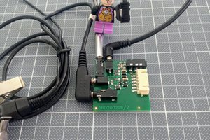
As I still wanted to be able to use the UA-25 for audio recording, I decided to make my changes reversible, or better switchable, possibly without opening the enclosure. Therefore, I created a small PCB with a 6 position SMD DIP switch positioned just under the lid, where I cut out a small hole), so I can switch on or off the digital high pass filter and switch between normal audio path or DC-coupled 0-5 V inputs (independently for each channel).

Some audiophile may also like to use the standard audio path with the digital high pass filter switched off for slightly better bass response. But then, don't forget to remove the DC offset in software before playing on loudspeakers if your DAC is also DC-coupled...  :-)

So these are the modifications needed:

- Unsolder and detach pin 16 of IC1 (CKS0) from PCB and make it switchable between ground and VD. The ground is available on a via just above the IC1, VD is available on a via just next to pin 7.
- Cut the PCB path between pin 1 of IC1 (AINR) and positive pin of C84 and make pin 1 switchable between either C84+ (audio) or the new DC-coupled right channel input.
- Cut the PCB path between pin 2 of IC1 (AINL) and positive pin of C76 and make pin 2 switchable between either C76+ (audio) or the new DC-coupled left channel input.

To save space, I used a 6 position DIP switch instead of 3 SPDT switches. The small new PCB is attached to the top PCB with double sided adhesive tape. To still be able to open the device and remove the top PCB, the new signal connectors are hooked up via ez-mate plug. I used magnet wire to make the connections between the small PCB and the UA-25 main PCB.

board_schematics.png

Schematics for the small PCB

Portable Network Graphics (PNG) - 40.11 kB - 01/06/2021 at 15:10

Preview

ua-25_mod_09.JPG

The 6 position DIP accessible from the closed lid

JPEG Image - 5.26 MB - 01/06/2021 at 14:44

Preview

ua-25_mod_08.JPG

JPEG Image - 4.32 MB - 01/06/2021 at 14:44

Preview

ua-25_mod_07.JPG

top view of the opened UA-25 with modification

JPEG Image - 4.72 MB - 01/06/2021 at 14:43

Preview

ua-25_mod_06.JPG

top view (detail)

JPEG Image - 4.57 MB - 01/06/2021 at 14:43

Preview

View all 11 files

  • Further Chips inside the UA-25

    mmueller-kaffeeschluerfercom01/12/2021 at 13:47 0 comments

    Further Chips inside the UA-25 (not complete):

    IC18, IC19, IC20, IC21, IC42: uPC4570 Dual OpAmp
    IC22, IC24, IC28: NJM2100 Dual OpAmp
    IC23, IC25, IC29: NJM4556A (Dual High Current OpAmp)

    IC2: LV08A
    IC3: TUSB3200AC (USB Streaming Controller)
    IC5: AKM AK4385 (2 channel DAC)
    IC7: I2C EEPROM, Label: "464I 45G2 4T", probably 24C64
    IC13: AKM AK4114 (Digital Audio Interface Transceiver)
    IC15: PC410L (Optocoupler for MIDI input)
    IC16: ??? Label: VHC 165 448
    IC17: ??? Label: 2008 561
    IC30: ??? Label: 56TI AIO

    IC31: TPS60111 (DC/DC converter for 5 V)
    IC33: NJM2374A (DC/DC converter)
    IC40: LV08A

    IC7 seems to be the EEPROM, most probably a 24c64 with pins 1-4 tied to ground, like in application example of TUSB3200 datasheet. The I2C lines are also connected to the CN2 connector to be able to flash the firmware...

View project log

Enjoy this project?

Share

Discussions

shipik wrote 03/08/2024 at 12:48 point

NIce mod!
Do you know how to start the device without PC?I want to use its analog part only, but it requiers to be plugged in to PC USB to start.

Thanks in advance!

  Are you sure? yes | no

mmueller-kaffeeschluerfercom wrote 01/13/2021 at 09:25 point

There's a hack here to make the advanced mode work with Windows 10 and MacOs 10.14. Mojave, by the way:

https://github.com/mmueller-kaffeeschluerfercom/UA-25-Firmware-Modification

  Are you sure? yes | no

mmueller-kaffeeschluerfercom wrote 01/13/2021 at 09:21 point

I can't talk too much about the use of the strain gauge because of an NDA, but to summarize, imagine objects falling onto one side of the strain gauge. Depending on some of the objects' properties, the deflection is slightly different. I need to measure this difference and also the maximum deflection. But the difference is very small compared to the maximum deflection and I still need enough SNR for the difference signal. To make matters worse, the range of the reached maximum deflection is also very high and I can't change the gain between occurrences.

Another use case for high dynamic range DC-coupled ADC is very accurate temperature measurements (e.g. ± 0.05 °C with an NTC) over a wide temperature range, which I happened to use for instance for monitoring crystallization processes.

What I also like about an audio interface when recording signals is the ability to make uninterrupted long recordings, e.g. unattended measurements during hours...

Are you using the UA-25 with Linux? Because on new versions of Windows and MacOs, the "advanced mode" is not supported anymore and then you get only 16 bit / 44.1 kHz... Fortunately, the "advanced mode" still works well with Linux.

  Are you sure? yes | no

Enrico Gueli wrote 01/12/2021 at 22:08 point

Nice! I'm using an UA-25 as I speak :)
Are you using a strain gauge for weight measurements? How come do you need such a high dynamic range?

  Are you sure? yes | no

Similar Projects

Does this project spark your interest?

Become a member to follow this project and never miss any updates