The UA-25 has two balanced AC-coupled inputs, some analog signal processing elements (mic/line preamps with optional phantom power, gain setting, optional limiter).
I opened the UA-25 and looked for the ADC. I found it to be the part "IC1", an AKM AK5381. The analog signal chain is AC-coupled to the ADC by two 22 uF capacitors, C84 and C76. That's where I decided to hook up my new inputs. As the ADC is powered internally with 5 Volts, it will give me a two channel, 0-5 Volts DC-coupled ADC which can acquire data directly with existing software like Audacity or Octave/Matlab.
The ADC inputs are internally biased to VA/2 with a 15 kΩ resistance (datasheet, p. 16), which is ok for my purpose (I'm driving them with an OpAmp).
Unfortunately, there is an internal digital high pass filter with -3 dB at 2 Hz (at 96 kHz sampling) in the AK5381 to cancel the remaining DC offset. But luckily, the HPF can be disabled in the AK5831, and again luckily, the AK5831 is used in slave mode in the UA-25, allowing to disable the digital high pass filter by connecting the CKS0 pin to 'high' instead of 'low' (see datasheet, p. 12).
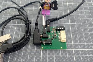
As I still wanted to be able to use the UA-25 for audio recording, I decided to make my changes reversible, or better switchable, possibly without opening the enclosure. Therefore, I created a small PCB with a 6 position SMD DIP switch positioned just under the lid, where I cut out a small hole), so I can switch on or off the digital high pass filter and switch between normal audio path or DC-coupled 0-5 V inputs (independently for each channel).
Some audiophile may also like to use the standard audio path with the digital high pass filter switched off for slightly better bass response. But then, don't forget to remove the DC offset in software before playing on loudspeakers if your DAC is also DC-coupled... :-)
So these are the modifications needed:
- Unsolder and detach pin 16 of IC1 (CKS0) from PCB and make it switchable between ground and VD. The ground is available on a via just above the IC1, VD is available on a via just next to pin 7.
- Cut the PCB path between pin 1 of IC1 (AINR) and positive pin of C84 and make pin 1 switchable between either C84+ (audio) or the new DC-coupled right channel input.
- Cut the PCB path between pin 2 of IC1 (AINL) and positive pin of C76 and make pin 2 switchable between either C76+ (audio) or the new DC-coupled left channel input.
To save space, I used a 6 position DIP switch instead of 3 SPDT switches. The small new PCB is attached to the top PCB with double sided adhesive tape. To still be able to open the device and remove the top PCB, the new signal connectors are hooked up via ez-mate plug. I used magnet wire to make the connections between the small PCB and the UA-25 main PCB.
 mmueller-kaffeeschluerfercom


 Christoph Tack
 Guy Dupont
 Datanoise
NIce mod!
Do you know how to start the device without PC?I want to use its analog part only, but it requiers to be plugged in to PC USB to start.
Thanks in advance!