 Mile
Mile-
1Things you will need
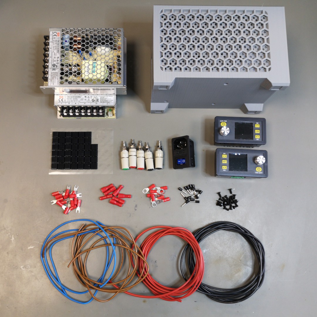
Bill of materials(quantity depends on your configuration):
- Enclosure DPS3003/5 Dual
- DPS3005 PSU module
- Meanwell LRS-100-24
- Front panel DPS3003/5 or T12 Soldering station
- AS-10[IEC320 C14] Socket
- BS-244DSM-R Red 4mm banana socket
- BS-244DSM-B Black 4mm banana socket
- BS-244DSM-G Green 4mm banana socket
- Stranded wire 1mm2 - Blue
- Stranded wire 1mm2 - Brown
- Stranded wire 1mm2 - Green/Yellow
- Stranded wire 1mm2 - Red
- Stranded wire 1mm2 - Black
- Quick connect Ring terminal M5
- Quick connect Fork terminal M3
- Quick connect Spade/Female terminal 4.8mm
- Cable ferrule for 1mm2 wire
- Screws M3x8mm Countersunk
- Rubber feet 3M PN:7000001895
- KSGER T12 soldering iron controller
- 19mm Illuminated switch
This is everything(almost) laid out on the table:
![]()
-
2Printing enclosure
Enclosure was printed on Prusa I3MK3S using default settings for 0.3mm layer height preset in PLA material and also it was printed on Ender 3 Pro using 0.6mm nozzle and default settings for 0.28mm layer height in PLA material. Everything printed without no problems and without using supports.
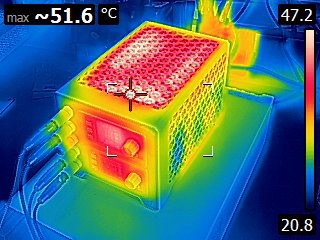
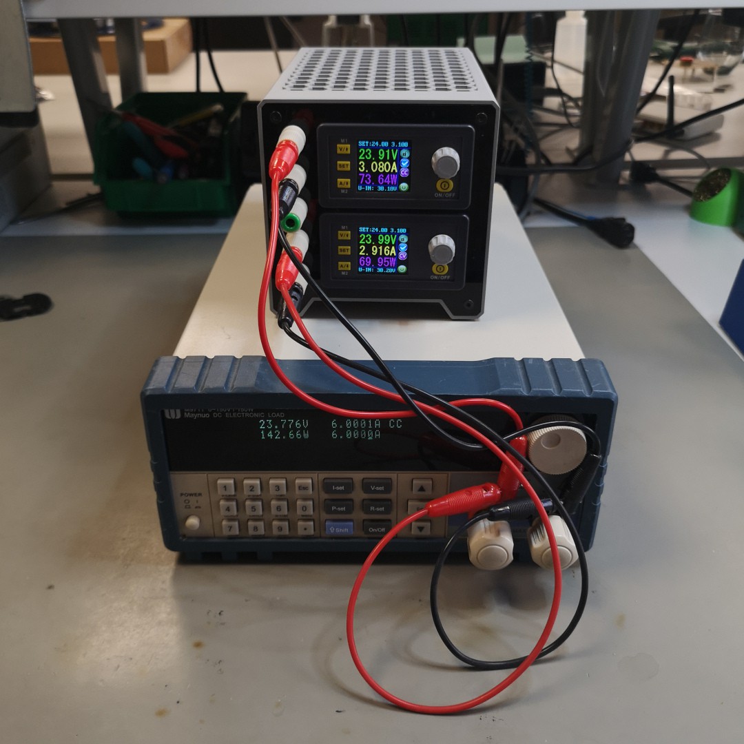
Here are some thermal cam images that show thermal performance of enclosure. Since I'm limited to 150W DC load I loaded each channel with 75W and let it run over night. As it can be seen the top of the enclosure reaches around 40 °C and sides around 30°C. This is expected since hot air is expanding upwards. There are also 50°C hotspots that correspond to internal placement of components(power transistors, switching diodes). I did test one channel with 100W load and temperatures were around 5°C higher. All tests were conducted at room temperature of 25°C.
During the test enclosure was mildly warm(sides barely noticeable) to touch and it felt that construction kept its rigidity.
This is the third revision of enclosure and first two versions are in everyday use for more than a year. They were used in lab environment for low power applications like powering electronic modules and high power ones like battery bank charging and they performed without issues.
![]()
![]()
-
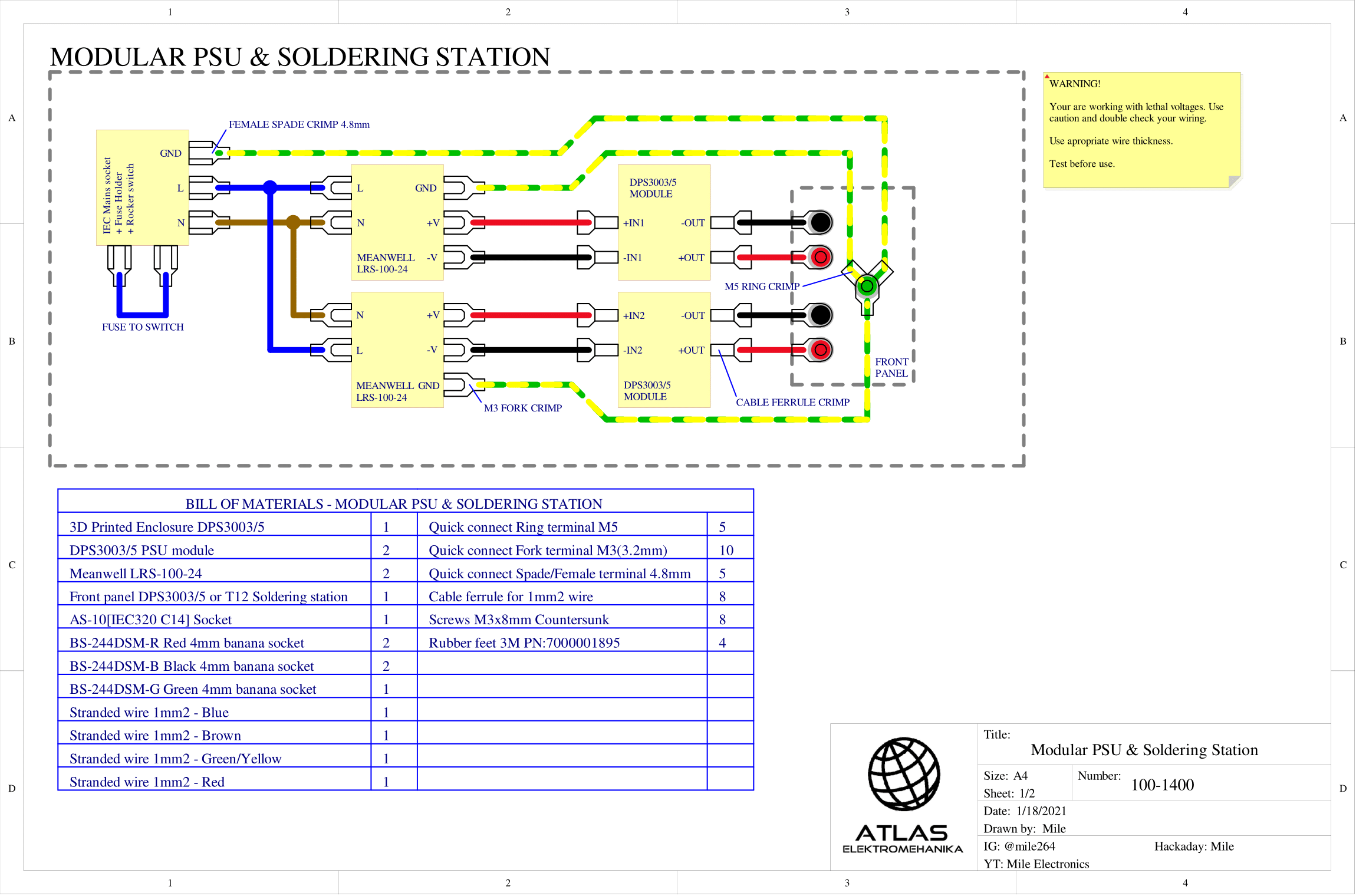
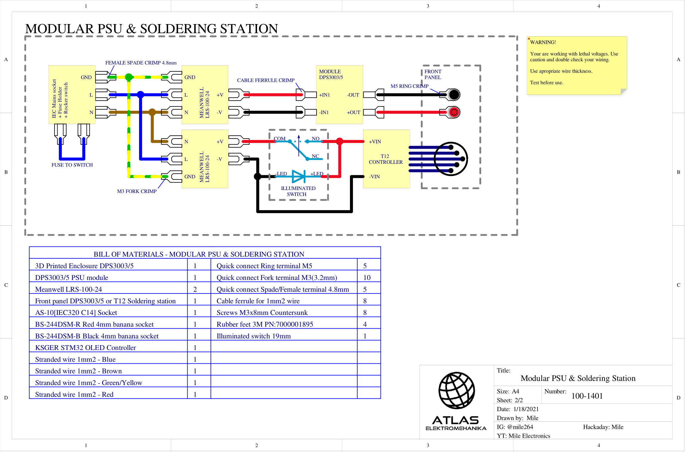
3Wiring instructions
For wiring schematics refer to images below(pdfs also available). First image shows wiring diagram for unit with two DPS3005 modules, while second one shows unit with one DPS3005 and KSGER T12 module. For more information about assembly refer to video above.
![]()
![]()
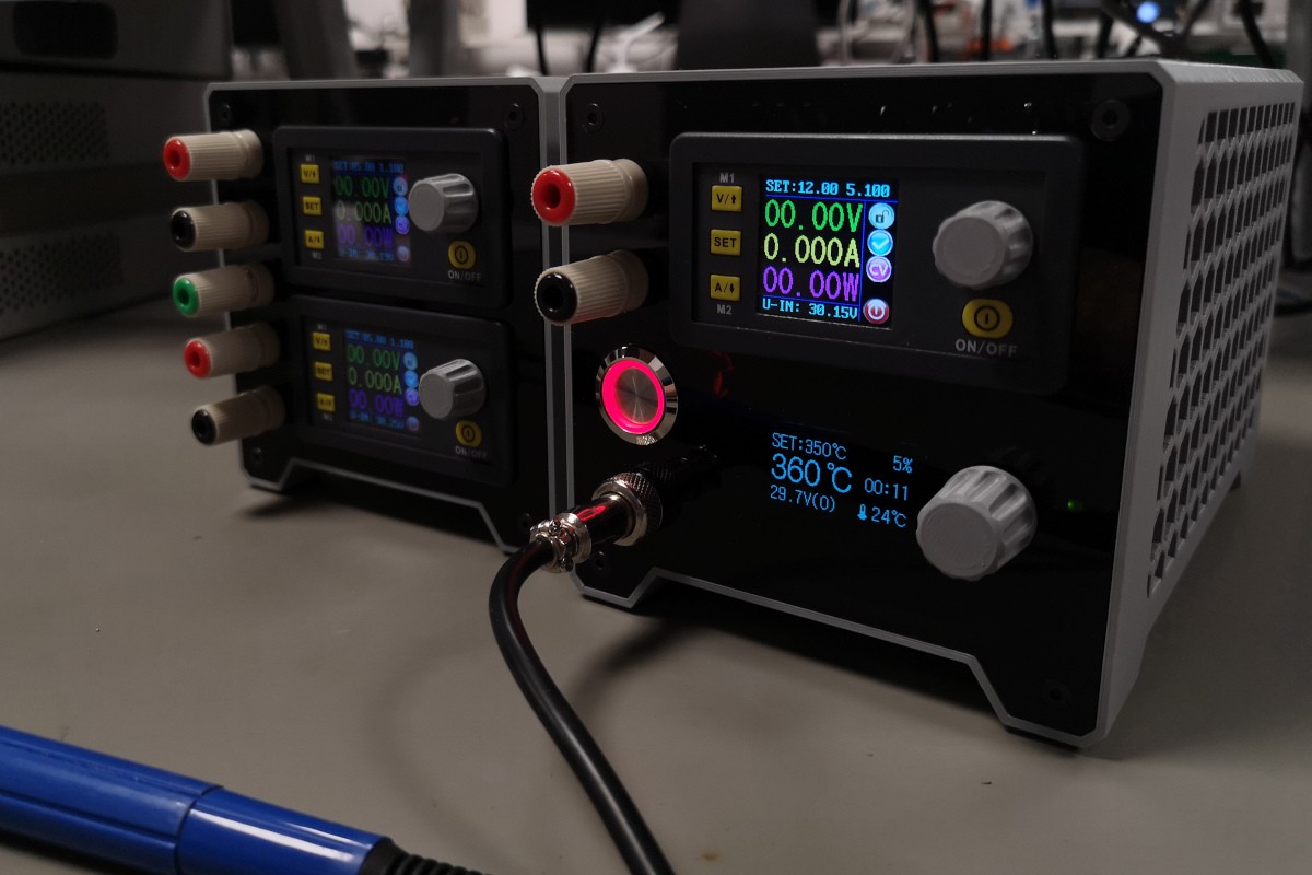
Your wiring should look something like this:
![]()
-
4Finished
All done. YAY!
![]()
Modular PSU & Soldering station
Universal enclosure that can be used as a lab power supply, soldering station or combination of two.

Discussions
Become a Hackaday.io Member
Create an account to leave a comment. Already have an account? Log In.