Close
0%
0%

RB0004 – NeopixelBooster

Power your WS2812B LED strips with 6-18 V and solve the "dim tail" problem

Public Chat
Similar projects worth following
Probably all of us makers love WS2812B - the addressable LEDs, which are often called "Neopixel" based on the brand created by Adafruit. They are so much fun to play with! Especially, when you can buy them in strips for less than 18 USD/5 meters!

These LEDs are, however, power-hungry and the strips are not the best design. Therefore you often struggle to power them - you need a 5V power supply with a large current rating. And these aren't easy to get. And if you get one, the strips behave weirdly - the end of the strip has more reddish colors compared to its beginning.

This is where RB0004 - Neopixel Booster comes in: it solves all the problems above.

RB0004 - Neopixel Booster

Probably all of us makers love WS2812B - the addressable LEDs, which are often
called "Neopixel" based on the brand created by Adafruit. They are so
much fun to play with! Especially when you can buy them in strips for less than
18 USD/5 meters!

These LEDs are, however, power-hungry, and the strips are not the best design.
Therefore you often struggle to power them - you need a 5V power supply with
a large current rating. And these aren't easy to get. And if you get one, the
strips behave weirdly - the end of the strip has more reddish colors compared
to it's beginning.

This is where RB0004 - Neopixel Booster comes in: it solves all the problems
above.

View this project on .CADLAB.io.

The Problem In Short

If you are interested in a much in-depth explanation of the problem with some
measurements, see the page about strips properties.

Each of the LEDs consumes around 60-70 mA in the full brightness (based on the
temperature and batch you have). Therefore, if you have 300 LEDs in a strip,
they will consume 18-21 A! That's a lot of current. When you push current
through a wire, there is a voltage drop according to Ohm'slaw. The copper wire on the strips
is relatively thin and narrow. Therefore, there will be a significant voltage
drop. It is quite common that you supply your strip with 5 V, but you will
measure only 2.5 V at the end of the strip. That means your LEDs can't shine the
full brightness.

But why they turn red? There is a red, green, and blue LED in the
chip. Each of the LED colors has a different forward voltagedrop - the blue one has the larges
one, and it is usually around 3 V. That means if the LED is supplied with less
than 3V, it cannot light up the blue channel, and thus, it is missing from the
final color.

You could solve that by just bonding a thick wire to the back of the strip.
However, a suitable wire for 21 A will be pretty thick (around 3.5 mm²).
Therefore, it is better to power the whole strip with higher voltage, thus
lower the current flowing in the wires and only lower the voltage locally for a
few LEDs. And that's what exactly Neopixel Booster does.

You run an extra wire around your LED strip and connect multiple Neopixel
Boosters in the strip to power it by segments:

Features
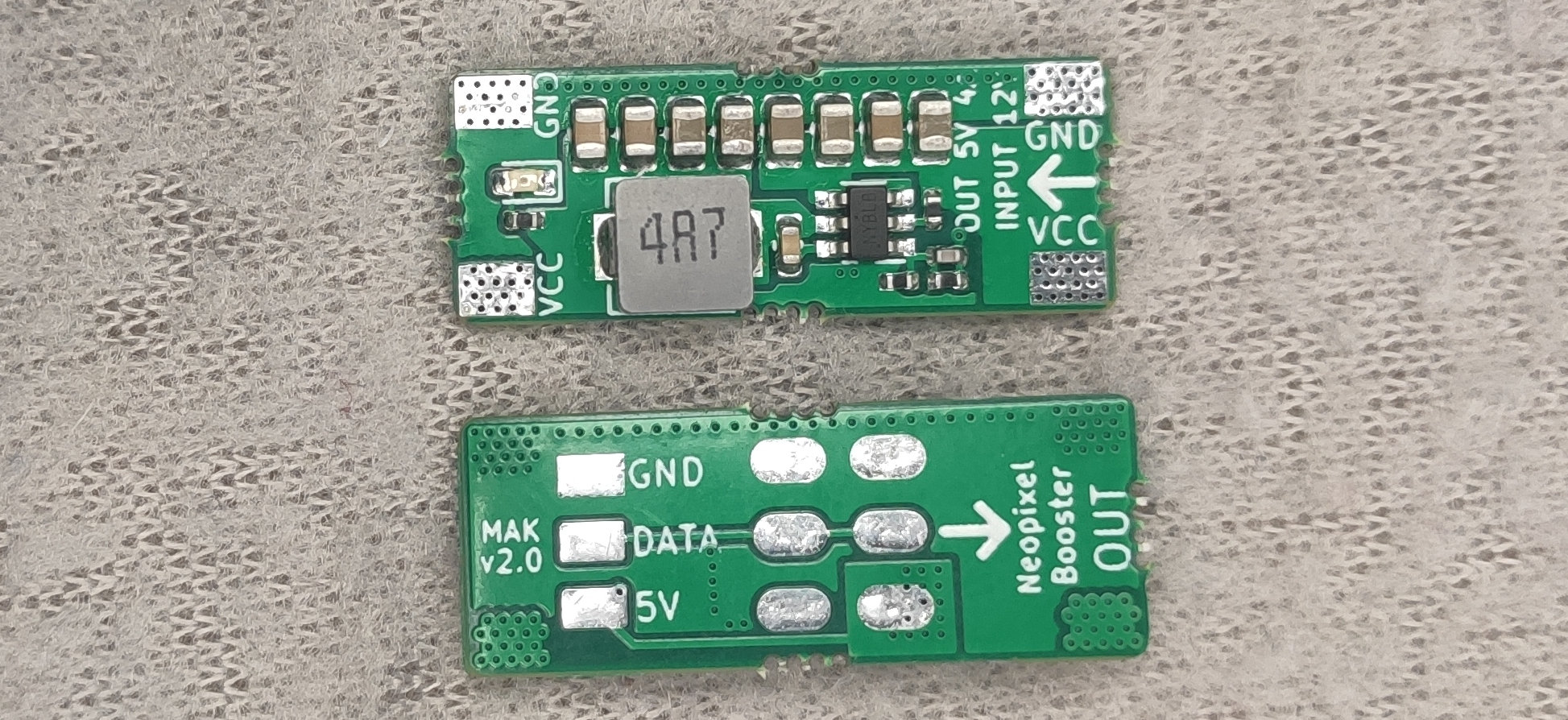
  • fixes the powering issue of the WS2812B LED strips on the market
  • you can power your strips with 6-18 V - higher voltage allows you to use thinner wires - when your power your strip with higher voltage, the power supply can have a lower current rating. - you can easily use a PC power supply for powering your LEDs. - you can easily power your strip from 2-4 Li-ion cells connected in series
  • requires relatively easy modification of the strip, see the assembly guide.
  • Neopixel Booster is step-down module; see its characteristics and performance.

I Want One!

You can get one from Tindie
How Do I Use Them?

Once you buy a kit from us, follow the assembly guide, and
within an hour, you can have your boosted strips.

How Many Do I Need Them?

We recommend not to exceed 60 LEDs per one Neopixel Booster. It is best for
convenient assembly to put one Neopixel Booster for each 50 cm of the strip, but
if you want to go cheap, it is OK to apply it every meter.


  • The modules are available again!

    Jan Mrázek02/01/2021 at 11:33 0 comments

    Thank you for your interest in the modules! I managed to manufacture a new batch, so if you didn't get your module in the first round, you can get them at Tindie.

    Also, thank you for all your comments; some of them were helpful and we're thinking about having a new version in a few months.

  • How does this compare to WS2815?

    Jan Mrázek01/12/2021 at 07:13 0 comments

    After publishing this project I got aware of the WS2815 LEDs, which can be powered from 12V directly. These LEDs have been released a year ago and I somehow missed that.

    So I checked their datasheet (http://www.normandled.com/.../WS2815%20LED%20Datasheet.pdf) and I have an interesting observation.

    Note that the following will be just a theoretical observation and since I don't have these LEDs, I cannot perform any real-world measurements.

    I bet that Neopixel Booster + WS2812B has better efficiency compared to WS2815. It seems that there is an internal 15mA linear constant-current regulator which is then dimmed by PWM. For the blue channel with that means that 70 % of the input power you burn into heat and then 30 % of the power goes to the LEDs. Meanwhile, with the NeopixelBooster solution, you step-down the input voltage to 5 V with 90%+ efficiency, and then you have the internal 15mA linear constant-current regulator (70 % of the energy goes to LED) - thus roughly 60% of the input power goes to the LED and only 40 % is turned into heat.

    The LED itself will have an efficiency of ~15-30 %, but it is the same for both cases, so I excluded it from my comparison.

    I should get some WS2815 and verify my observation in practice.

View all 2 project logs

Enjoy this project?

Share

Discussions

Zleeping wrote 09/11/2022 at 16:42 point

I am new to Hobby electronics and made an addressable display that ultimately failed due to power issues. Some questions, I have read to put a capacitor at VCC to control abrupt changes in current. Do I use one at each module? Before or after the module?  So if im using 300 leds I could use 6 modules. Without the module Id need 5 volts 18 amps, I think but if I go to 12 volts is it 4.5 amps? im so clueless with math and OHMS law.

  Are you sure? yes | no

[deleted]

[this comment has been deleted]

Jan Mrázek wrote 01/18/2021 at 18:53 point

Hello, the PCB is 4 layer one. So there are 2 nearly full planes that transfer the VCC from one side to another one.

  Are you sure? yes | no

Shannon Wynter wrote 01/13/2021 at 20:04 point

This is sweet!

I do wonder tho, if one is trying to cram this into aluminium channel, how well does it fit. It'd complicate the manufacturing but could the board under the coil could be cut away and the coil embedded in the board, it's only a couple of extra mm but would mean it'd fit in tighter spaces.

Edit: and now I look at it, I wonder if a bit of trickery couldn't be used to reduce the gap created (I mean it's pretty minor as it is) by taking the input on one side of the pcb and output on the other side so the pcb actually ends up sandwiched between the end of the stips (think Z), but that's me pondering aesthetics over function :D (would make them harder to daisy chain)

  Are you sure? yes | no

Jan Mrázek wrote 01/13/2021 at 20:21 point

Thank you for your idea! The PCB has the same width as the strips. When you install it into an aluminum channel, you can put the coil directly on the aluminum - there should not be a short circuit (I haven't tested this setup though). It could be actually beneficial - the thermal capacity of the inductor is the limiting factor of the current design. During my measurement, I found out that cooling the coil improves efficiency (unsurprisingly).

The thickness of the whole PCB is 3.9 mm in the thickest area (across the coil). I am a little bit skeptical about the coil mounting you propose - not only that it would only save a single millimeter (the thickness of the PCB, but it would also drastically reduce the copper cross-section which carriers the current between from and back VCC pads.

To make the whole assembly thinner, it would make sense to use a thinner coil with a bigger footprint, however, I haven't checked if such coils are available. Also, it makes not much sense to reduce the thickness below 2.4 mm - that is the thickness across the caps. Also, remember that you have also considered the thickness of the power wires you solder on your pads. 

  Are you sure? yes | no

Hakaday wrote 01/13/2021 at 16:28 point

Fantastic solution.  Thanks for cooking it up and making it available.

Inspecting the pictures of the board, I don't see any trace, much less anything capable of high current, to the output VCC pad (closest to the big inductor).  A quick scan of the PCB files didn't reveal more than the two surface copper layers.  The JP is there on the schematic, though.  Am I missing something?

  Are you sure? yes | no

Jan Mrázek wrote 01/13/2021 at 19:59 point

Hello, the PCB is 4 layer one. So there are 2 nearly full planes that transfer the VCC from one side to another one.

  Are you sure? yes | no

JHB wrote 01/13/2021 at 07:15 point

nice work, what about a version that can handle 24V or more?

  Are you sure? yes | no

Jan Mrázek wrote 01/13/2021 at 20:03 point

Thanks. This project is a collaborative project with people from RoboticsBrno (https://github.com/roboticsBrno). I was at the design stage of this version and back in the day, 18 V was sufficient for our needs and the IC controller was a convenient one. However, my friends have been thinking about the 24V version for a few weeks now - so maybe in the near future, we will also release a 24V version.

  Are you sure? yes | no

Similar Projects

Does this project spark your interest?

Become a member to follow this project and never miss any updates