 Vipin M
-
1Assemble the base
- Secure the motor and slipring to the mounting bracket using 3mm screws and nuts.
- Attach the mounting bracket to the standoffs in the base.
- Insert the barrel connecter and the power switch to the appropriate openings in the base.
- Before wiring up the motor and slipring with the supply, make sure that the slipring is installed with its collar resting on the mounting bracket.
- Situate the ESP8266 and wire it up as per the connection diagram in the instructions.
- Install the slew bearing after lining up with the tab on the side of the base. The bearing will rest on a small ledge located on the inside perimeter of the base.
- Test and make sure that the motor can drive the slew bearing without binding.
-
2Assemble the canopy
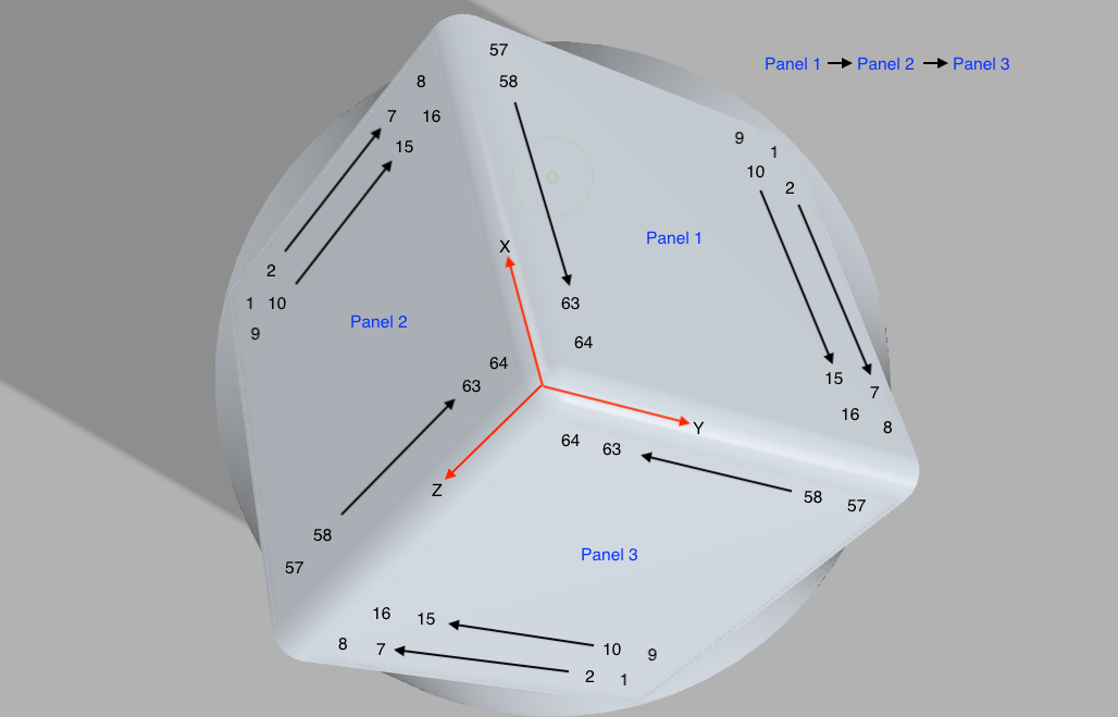
- The Neopixel panels go on the 3 faces and have to be installed in a specific pattern and orientation for the display to work as per the default software configuration. The illumination patterns are achieved using a pixel map derived from the coordinates of each pixel in the 3D space. You can think of the 3 panels as 3 orthogonal faces in the cartesian space joined together at the origin. As such, the faces can be treated as XY, YZ and ZX. Refer to the picture in the project instructions.
- Each panel has an input port and an output port with voltage, ground and a control signal line. The panels have to be connected in series with the output of first going into the input of second and the output of second going into the inputs of 3rd.
- The panels have LEDs in a non-serpentine pattern. It is easily configurable in the software if the pattern is opposite. Note that a panel can be installed in 4 different orientations on a given face. Again refer to the instructions to ensure the correct orientation. I will admit that it was a bit tricky to orient them the first time. Of course, it is not the end of the world if you get it mixed up. As long as you know, what you have and how you have installed it, you can change the pixel map in the software and get it to work.
- Clip the wires long enough so that they can be brought outside from the small opening in the bottom face of the canopy. Color coding can make the life a lot simpler. I chose to go with Red for Vcc, Black for ground and identical color for a given pair of input and output signals that have to be connected together. I then twisted the 3 wires from each port and brought them out. Next connect the input and output stages. At the end, it will leave one set which has to be connected to the turning portion of the slipring. The fixed portion of the slipring is connected to the output from the base.
Refer to the following layout for connecting the Neopixel panels.
![]()
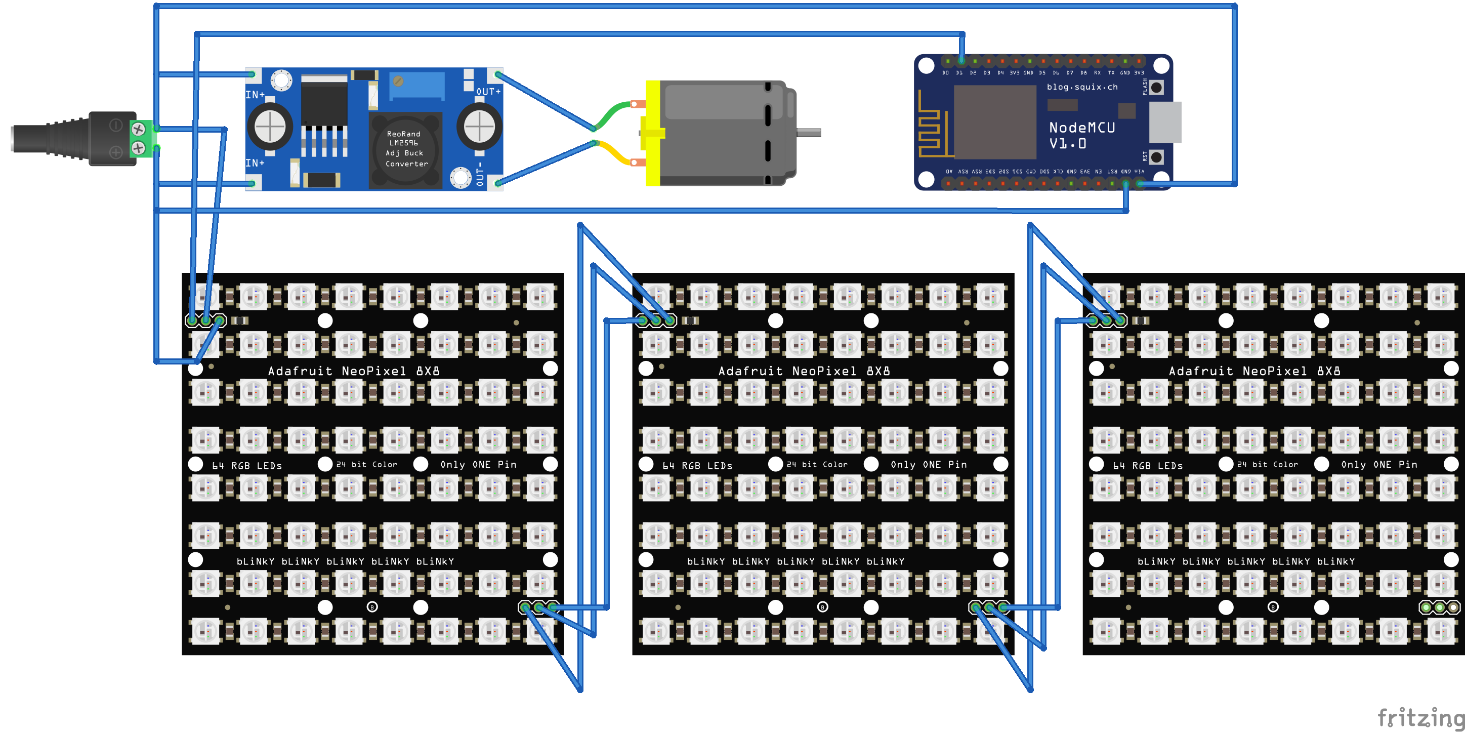
Refer to the following circuit diagram for wiring.
![]()
-
3Join the base and canopy
- Snap the base and canopy together after lining up the 4 slots.
- Turn it on and enjoy!
Discussions
Become a Hackaday.io Member
Create an account to leave a comment. Already have an account? Log In.