Marcelo
-
Four-bit comparator circuit
04/20/2021 at 18:17 • 0 comments
One of the great advances in computing was made by the German Z4 computer from 1945. According to a book, it was capable of comparing numbers within its programming.

Z4: front view of operating console with relay cabinets in background. Deutsches Museum Some days ago, I began to develop a unit capable to compare two numbers in order to add this capacity to my Paper Clip Computer.
Yeah, I know, I know.... the numbers that this computer can manage are small how to need a "comparator unit" but the pleasure was not in the "needed" but to build it and add it.
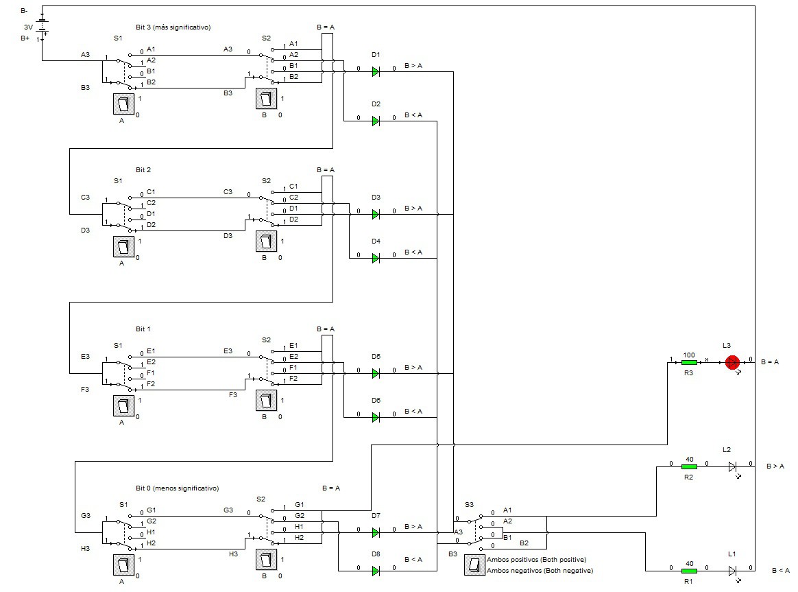
Searching the Internet I did not find a four-bit comparator circuit without chips; my goal was to follow the principles and philosophy of the computer: no chips, just basic electronic components and switches.As I did not find any circuit, based on the book I created mine which is the one that I expose below.
![]()
This circuit is capable of comparing two four-bit numbers with the only limitation that both must be positive or negative; if one of them is negative, this will be the lowest.
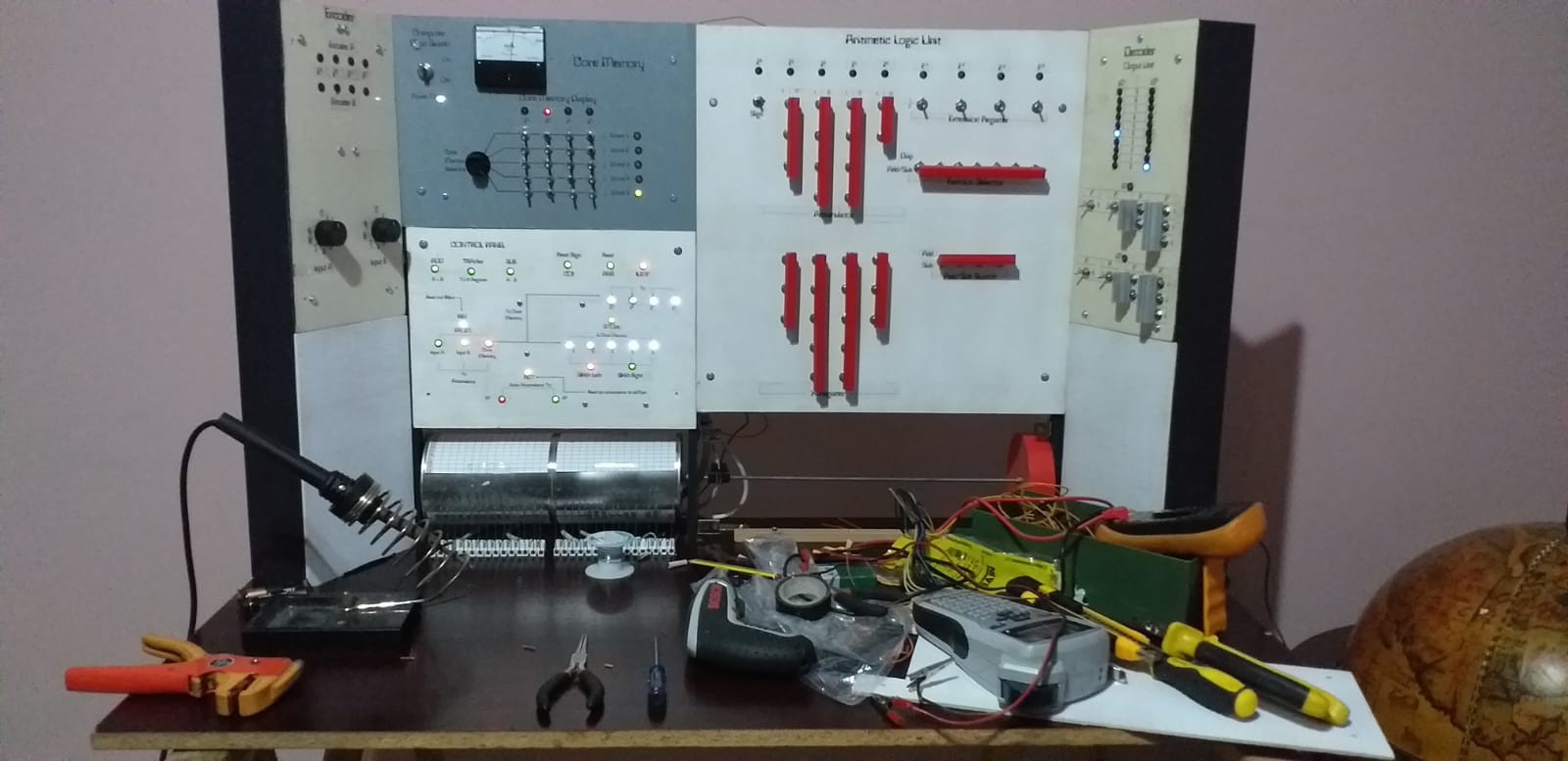
I will try to build the circuit that will be integrated into the computer (and the drum) in a blank panel that is on the left of the model and it will look like this:
The comparator will add one more command:
COMP
whose parameters will be:
COMP <Word 1> <Word 2>and Word n should indicate:
- two of the five memory locations
- accumulator and a memory location
- the Encoder
The result of these two parameters will indicate whether:
Word 1 > Word 2Word 1 = Word 2
Word 1 < Word 2in the light panel.
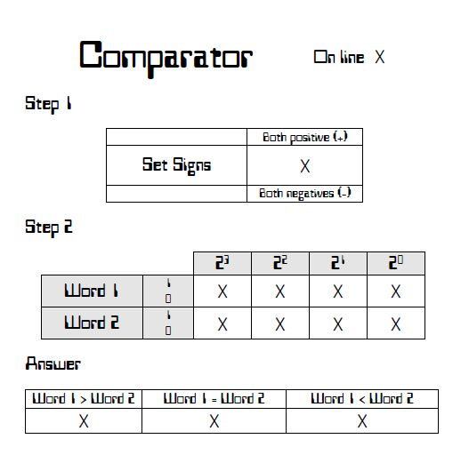
The operation
The operation will be simple:
Step 1: Indicate is whether the numbers will be positive or negative.
Step 2: Select the position of the individual bits.
Answer: Read the result and use it according to the instructions of the program. -
Cabling system
01/23/2021 at 23:13 • 0 commentsToday I finished wiring the Control Panel. From the beginning of the project I tried to make it modular since the search for possible errors and maintenance would be much easier.
![]()
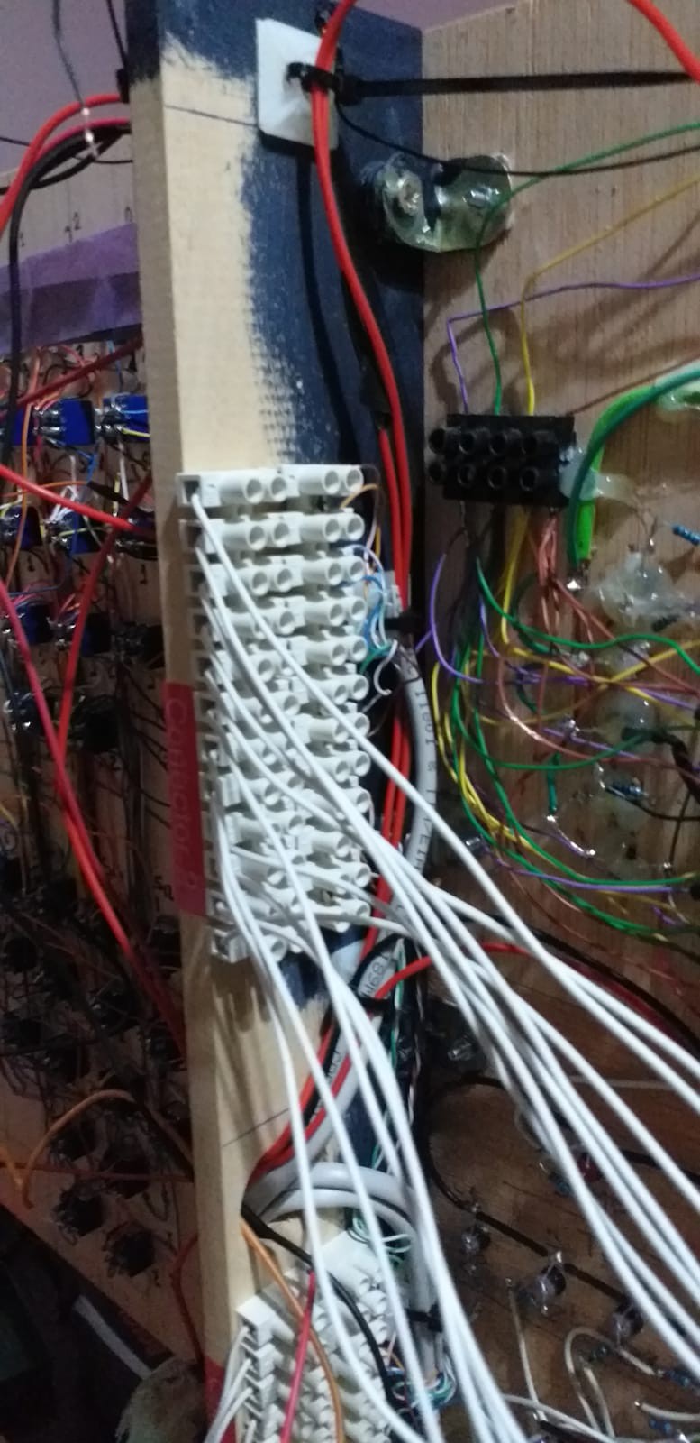
Making the system modular consumes more time since instead of just "placing" a cable I placed terminals and connectors; debugging or replacing damaged components should be easier this way.
![]()
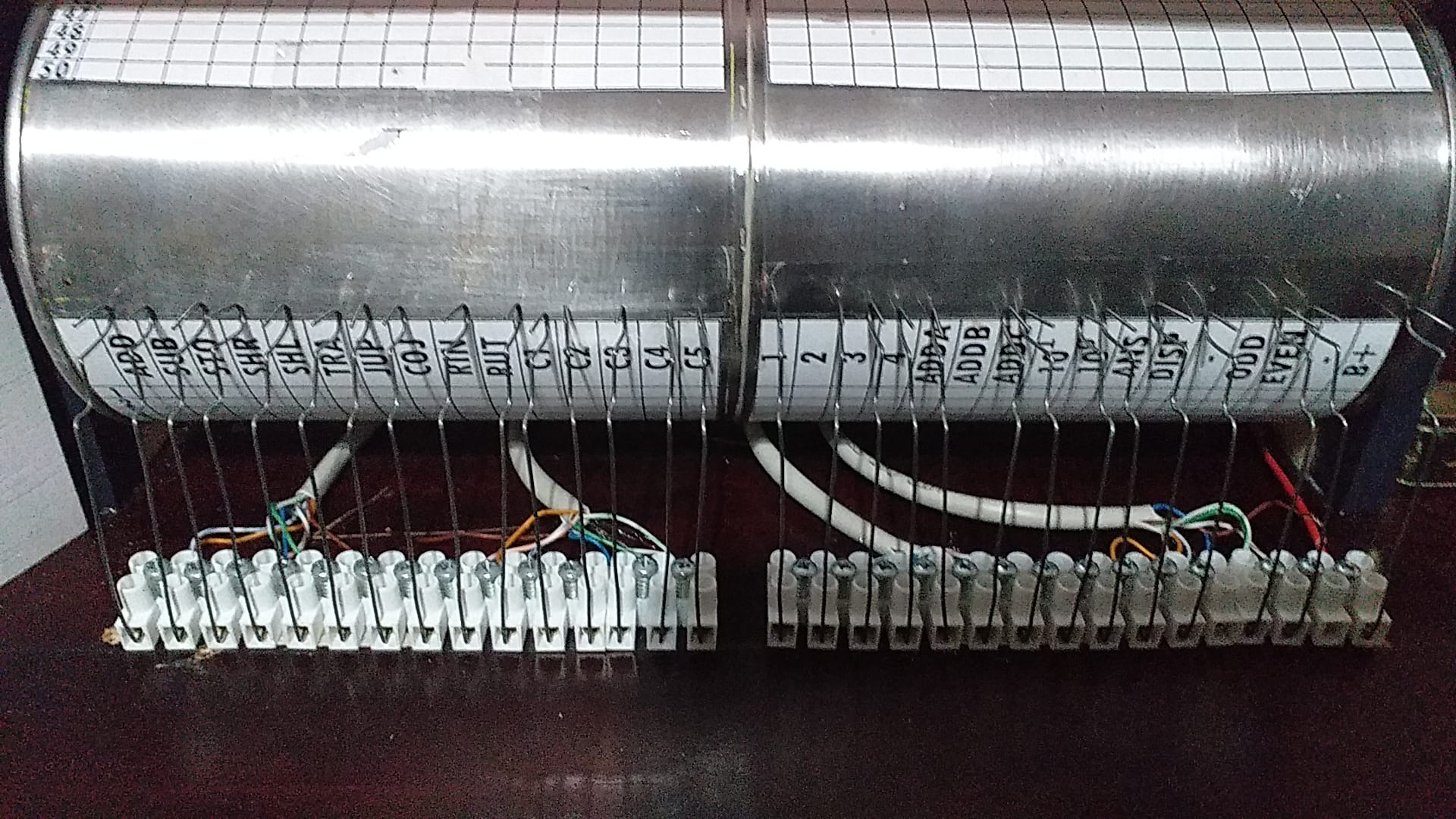
All cables and connectors are either color-coded (I used network cables) or are numbered so they can be easily identified. I also made an Excel with the cable-number-computer word equivalences to print it and stick it on the inside of the back cover and include it in the operations and maintenance manual.
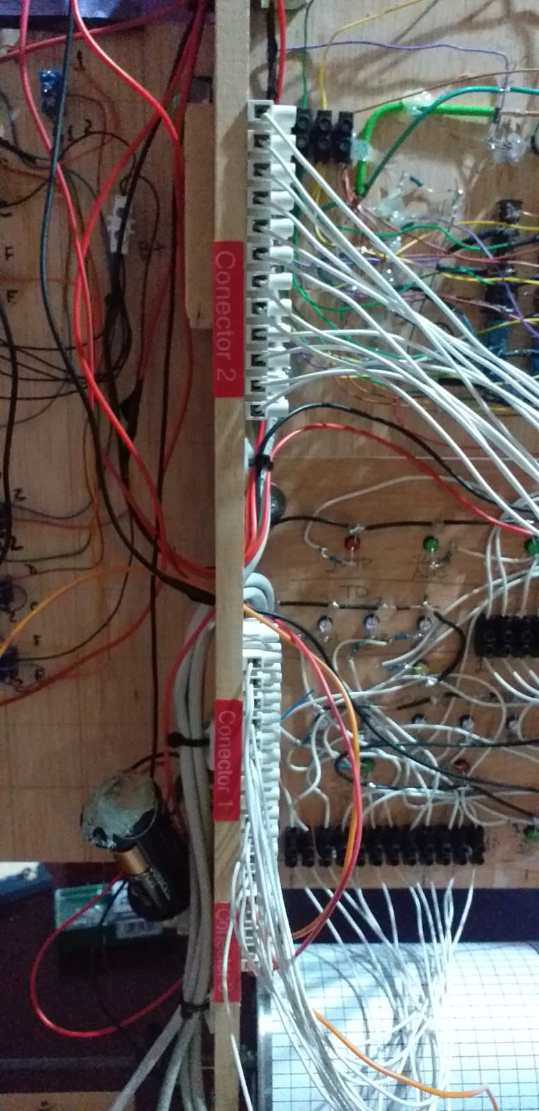
![]()
With this modular format I can quickly disconnect all the panels to remove them from the chassis, repair them independently from the rest of the equipment and once tested, reconnect them.
Today's work was to place the connectors coming from the Control Panel and to place the "reading heads" on the drum, which work but sometimes the contact fails to what I think is the poor quality of the wire used for the paper clips. Tomorrow I will try to buy one of better quality.
PaperClip Computer
A few months ago I discovered "How to Build a Digital Computer That Works" and got excited about the project.